I am trying to use this laser engraver/cutter (Oakeroo 7.5 W Laser Moudle Head Adjustable Lens Engraving) I picked up on amazon. According to the board it should accept a pwm signal up to 12v, and control the laser accordingly based on the duty cycle. I’m using a Bigtreetech SKR 1.3 board
I specifically picked this laser because it is supposed to work with the 12v output of the fan, but I cannot seem to control anything no matter what I do, the driver always shows 100% output (and seems to give 100 when hooked up to the laser)
I had a similar experience when working with a laser hooked up to the fan output on a RAMPS board running Marlin. The problem I found was that the PWM output was inverted so that “0” was 100% or laser full and 255 (or 1000, whichever your range is set to), was 0% or laser off. I ended up having to build an inverter circuit and after that it worked like it is supposed to. Try telling whatever control software you are using to set the fan at full and see if your laser turns off.
EDIT: Just checked out the laser you are using, it’s the exact same one I have, except mine was sold under the NEJE name. Are you trying to connect to the 2-wire TTL input plug on the test board, or are you wired directly to the laser head?
The laser is looking for +ve pulses on the PWM pin and your SKR is outputting a solid +12v on the fan output +ve and pulsing gnd on the fan output -ve. You will need to invert the fan output as Tim suggests…
Hello Mike,
I really hope you can help me. Please.
I have exactly the problem you are describing here.
My GT2560 Rev A is outputting +12v on fan +ve and pulsing gnd on the fan output -ve.
I need to pulse the the +ve output to drive my Neje N40630 laser…
How can i do this? is there a software way to change this outputs? or do you have any suggestions?
Thank you A LOT for your suggestions…
I assume you are running Marlin. The N40630 laser can be driven by 5.0V pins, so the path of least resistance is to redefine the fan pin to an available 5.0V pin on your board. You should find the pins files for your board in the pins/mega folder.
Note driving the laser using fan commands produces subpar laser engraving results. The better solution is to enable laser support in Marlin (and you will use a 5V pin to drive the laser). V1 enabled laser support in the Marlin firmware for the Rambo board, so you can use a difference tool to compare the configuration_adv.h file for your board with the configuration_adv.h of the Rambo board to see what lines need to change. For the Ramps board, seven lines needed to be changed. Meld is one difference tool. After enabling support, you can use either M3/M5 commands or inline commands to drive your laser.
It depends on what you want to do with the laser, if you just want to cut stuff out then you don’t need pwm, you just need the laser on or off, this can be achieved using the fan output on your gt2560. If you need greyscale then, as Robert suggests, you need a ‘proper’ pwm output. You don’t say which GT2560 board you have, or which firmware you are using. To be honest, the GT2560 is not, IMHO, the best board to start with, there don’t appear to be any spare pins brought out on the board and it is a Mega2560 processor, so some of the processor pwm capable pins are useable… and some are best not because of erratic startup behavior.
I am a firm believer in the KISS principle and would use GRBL and a cheap and cheerful UNO/cnc shield type 328P based solution for a simple laser machine rather than a frigged version of a 3d printer board and firmware… sorry.
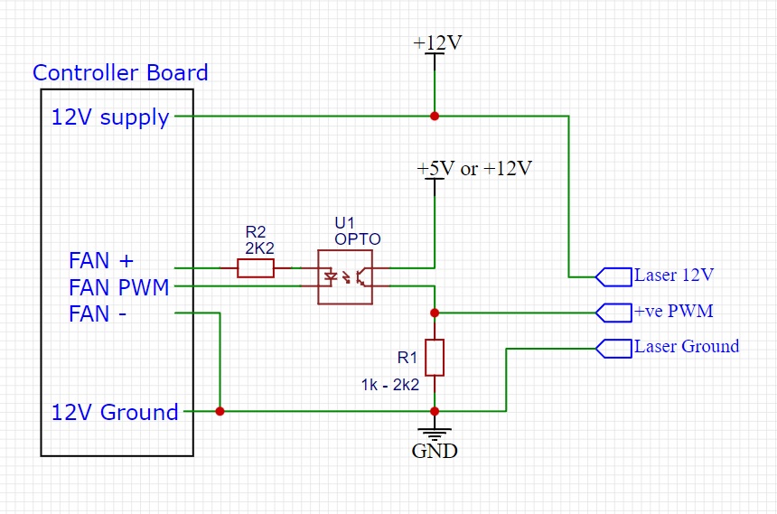
Having said that, you could use an opto-isolator to convert the fan PWM signal to a ‘proper’ +ve pulsed PWM signal to feed into the laser, something like this -
Thank you both Robert and Mike for the prompt reply and good suggestions.
Yes i am running marlin, on the GT2560 rev A of my old 3d printer that i wanted to recycle for laser cutter and greyscale engraver.
I would like to give a try to reuse the Gt2560 and enable the laser support in Marlin using a pwm pin (the neje laser I have can also be driven by a 12v pin, if it helps…), but can you please help me find if there is one good/usable pwm output pin?
I will check tonight the configuration_adv.h file and see if I understand something… I am not practical at programming…
Using a Uno/CNC shield would be perhaps simple and better but as i would like to use the lcd and its commands knob to start prints from SD without be connected to a computer (i will have to put the machine somewhere else because of the fumes)… maybe it is not the solution.
Thanks for your help…
Different firmware is not going to solve the underlying problem of the fan pins being ground-side switching. A number of people on the forum successfully use Marlin with laser support enabled. It is what I use. I’ve never seen a head-to-head comparison of different laser firmware on similar boards, so it is hard to say what impact the firmware plays in the quality of the laser engraving and cutting.
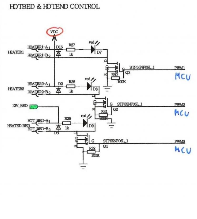
From what I can tell, your board doesn’t break out any extra pins. I found a possible schematic in this forum post. If you want to use this board, I think figuring out how to use a 12V PWM pin is the path of least resistance.
Looking at the schematic, I find four 12V PWM pins that could be used to drive the laser.
You can assign a fan pin as the laser pin as used by the laser support in Marlin, but you will need some additional circuitry to address the ground-side-switching issue. I believe I’ve seen a few circuits in posts on this forum to address the issue including Mike’s one above.
Edit: After finishing the above, I did a bit of searching on the forum to see if I could find any of the other circuits diagrams. I found this post, which Mike (@dart1280) also posted. Maybe he can compare and contrast the two circuits. I know I’ve seen a couple of other solutions as well, but they did not show up in my searching.
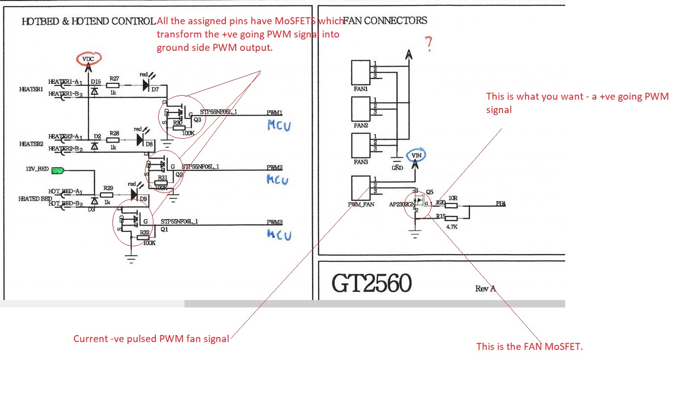
OK. The problem with using any of the pins already assigned to different functions is you have to -
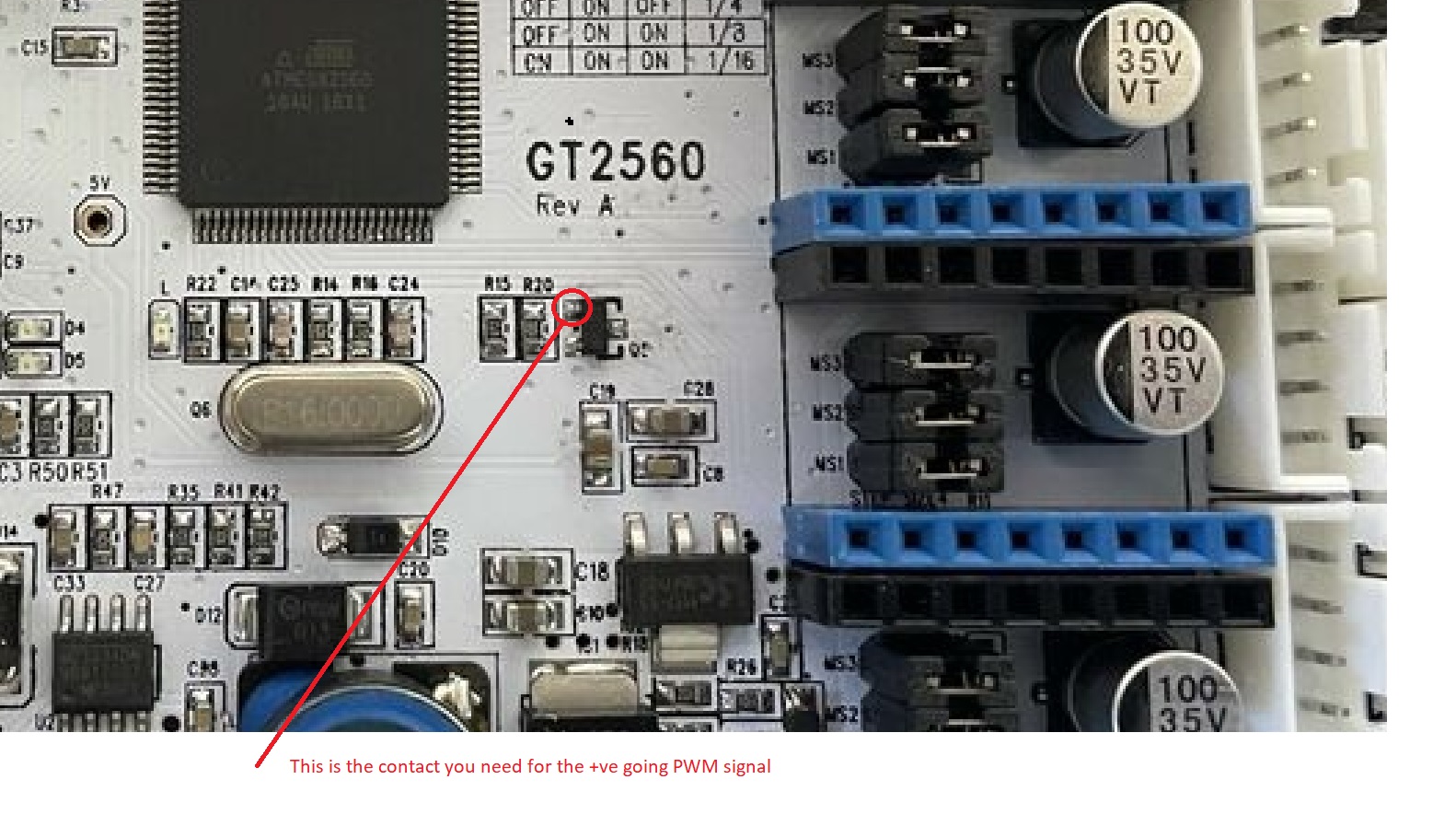
a) get onto the MCU side of the MoSFET drivers in order to utilise the +ve going PWM signal and as they do not appear to be broken out to any kind of test pin it means some VERY careful soldering…other than that I suggest using the opto-isolator approach. (I wouldn’t use the previous cct that I found that used a transistor because of the reasons stated in the followup post…the +12v gate voltage being higher than the collector voltage)… and
b) As I understand it, you are going to have to remove all references in Marlin to the current control of those pins if you want to assign the pin to laser_pin and use M3/5 to drive the PWM in laser mode. I’m not saying this can’t be done but do you need the hassle, it is quite a steep learning curve as it is.
Like I said, I prefer the simpler path and Robert knows more about the Marlin side of things so I think I will leave you in his capable hands.
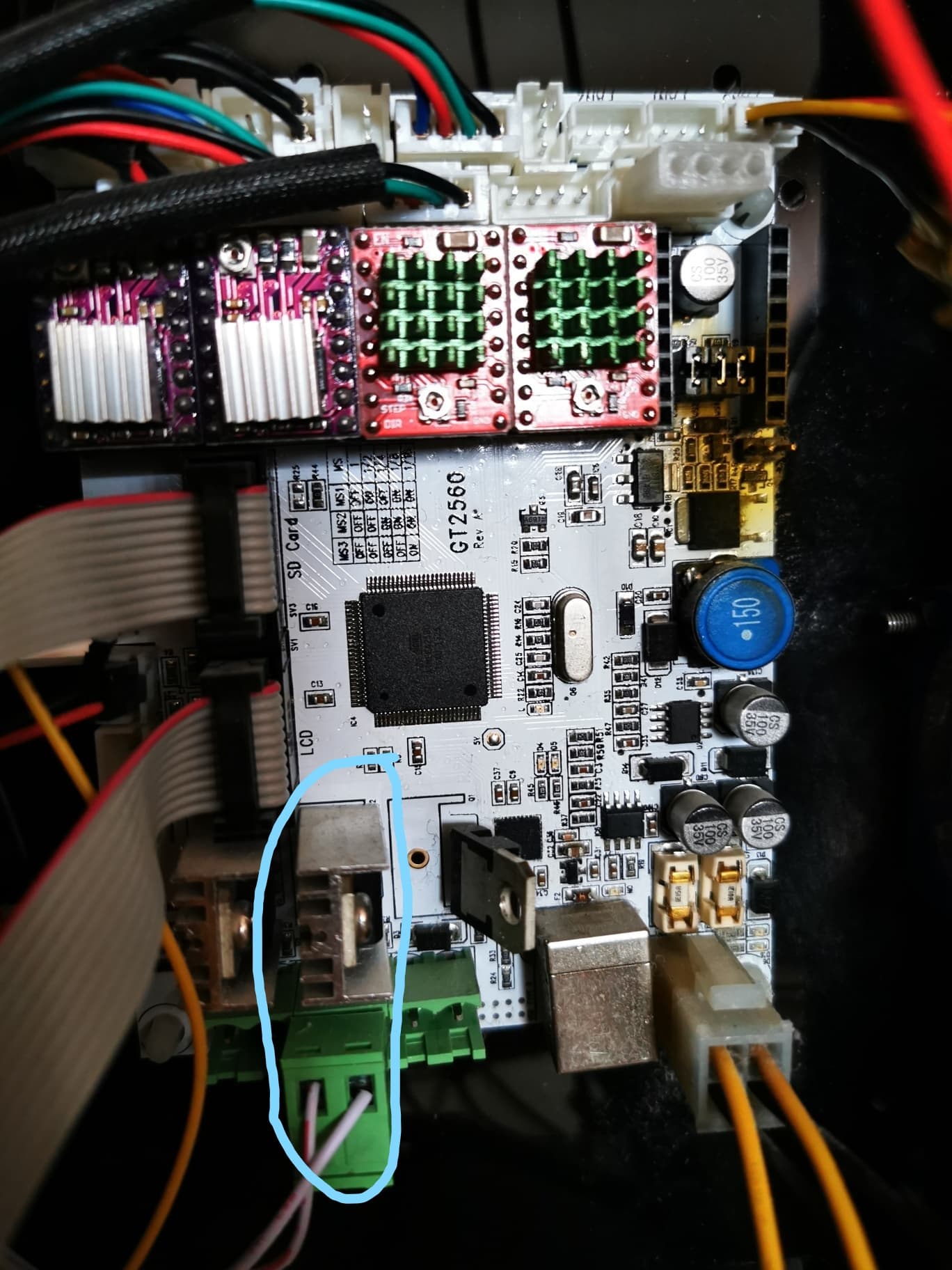
Hi Mike, thank you for your suggestion… unfortunately i fried the mosfet trying something… : (
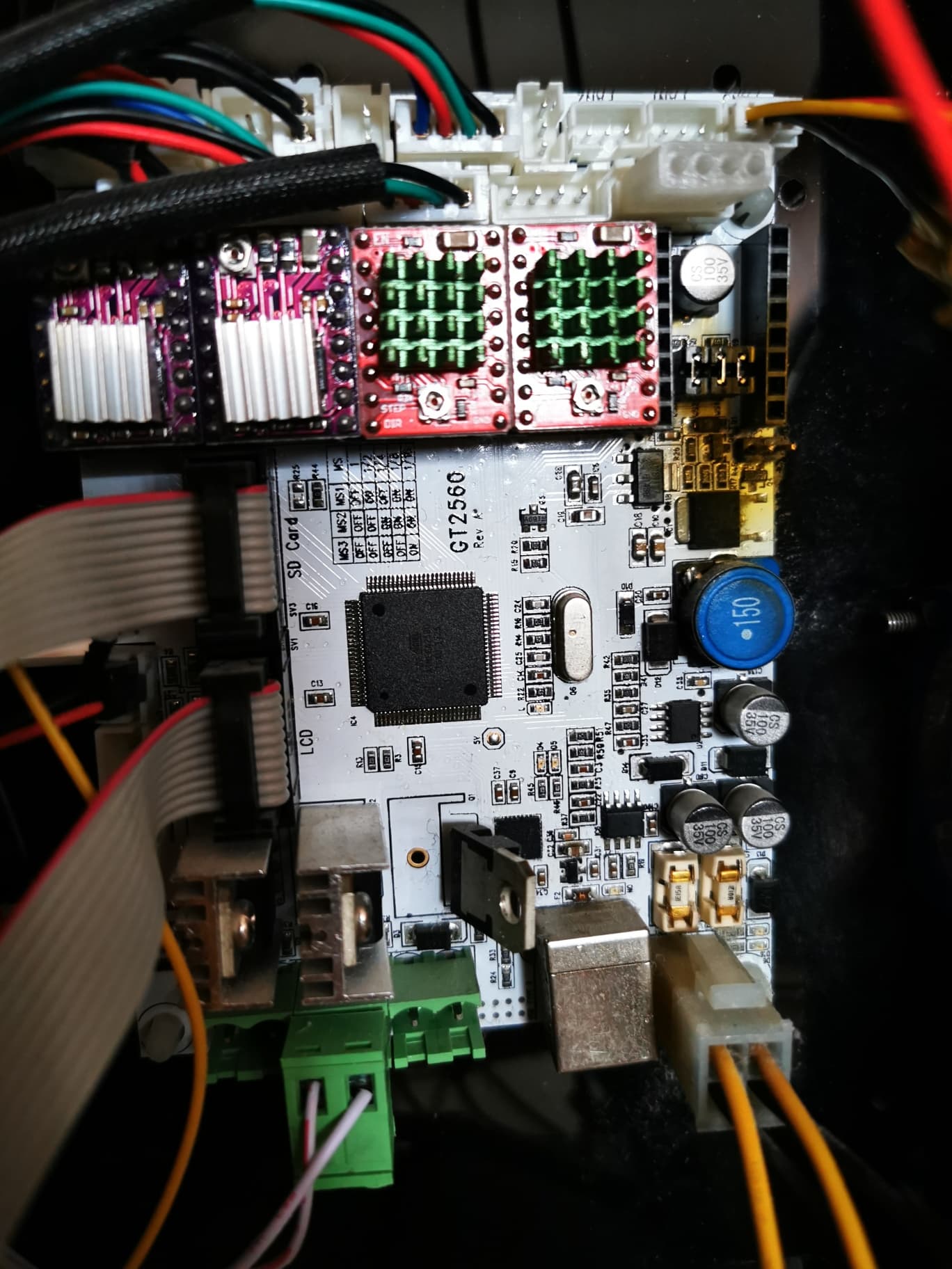
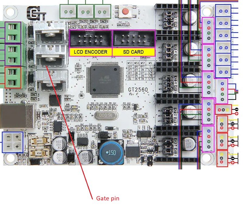
But i managed to modify the pinout so that noe the fan pin is on one of the bigger PWM outputs, the NR. 3 (normally extruder 2) Maybe you can tell me where to get the +ve going PWM on the big mosfets of this exit? The mosfet is the one in the middle that you see here
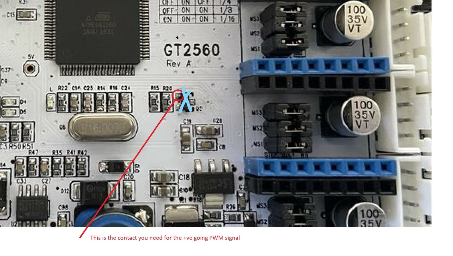
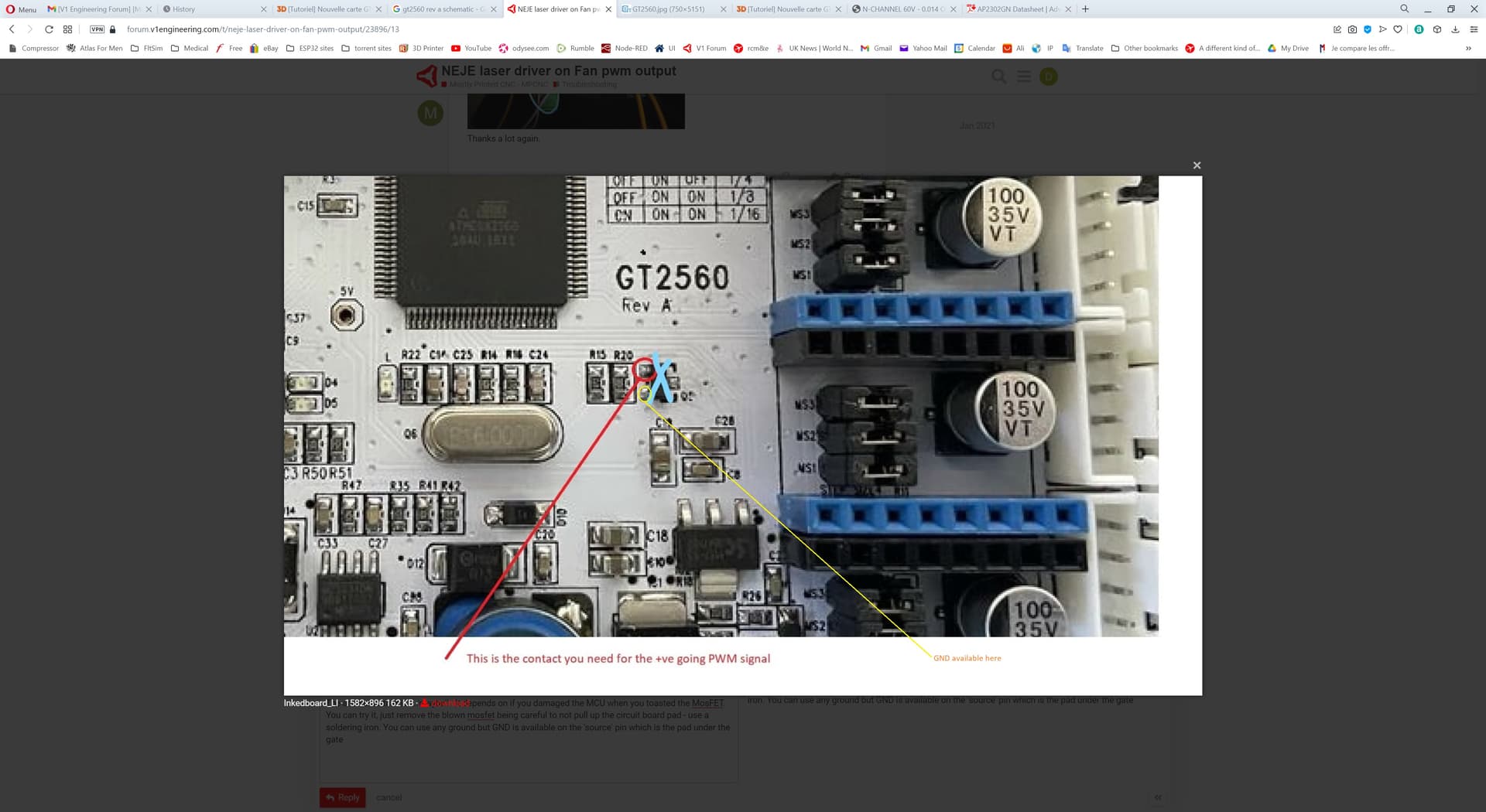
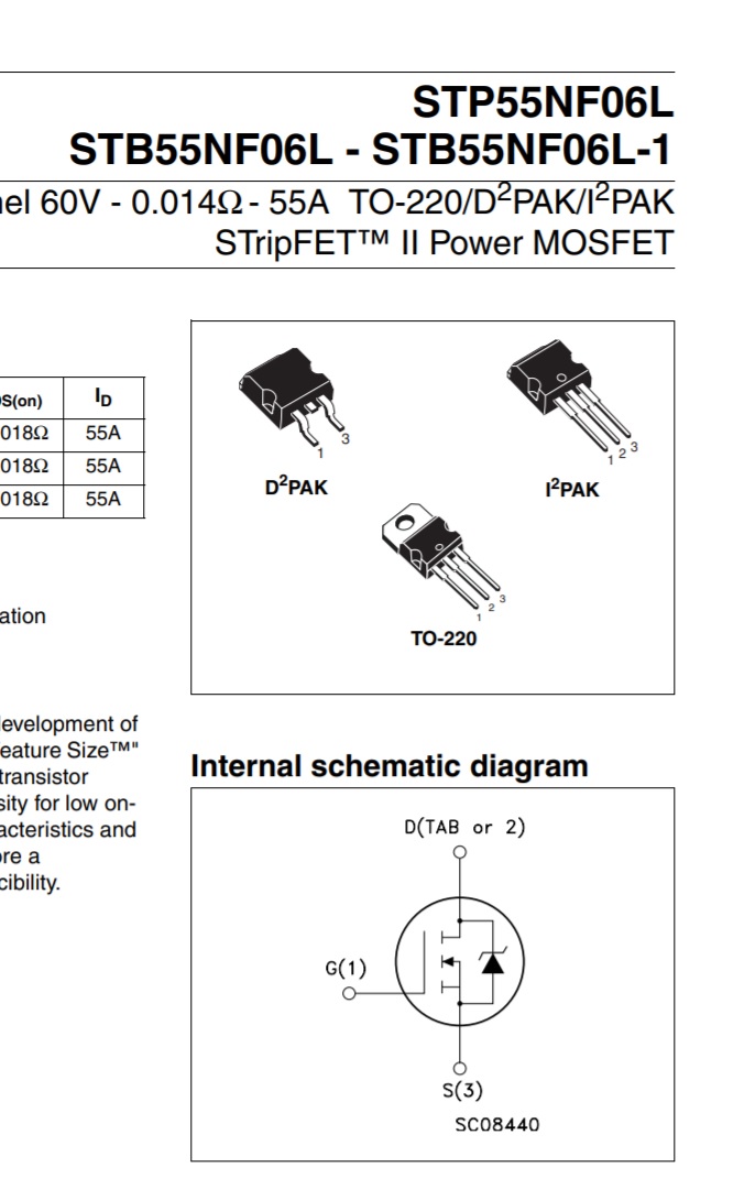
The answer to that is…‘maybe’! It depends on if you damaged the MCU when you toasted the MosFET. You can try it, just remove the blown mosfet being careful to not pull up the circuit board pad - use a soldering iron. You can use any ground but GND is available on the ‘source’ pin which is the pad under the gate
Again, you can remove the MosFET and solder to the gate (PWM) and source (pin 3) (GND) pins …however, configuring the firmware to allow the use of that mosfet for laser pwm out is another question…
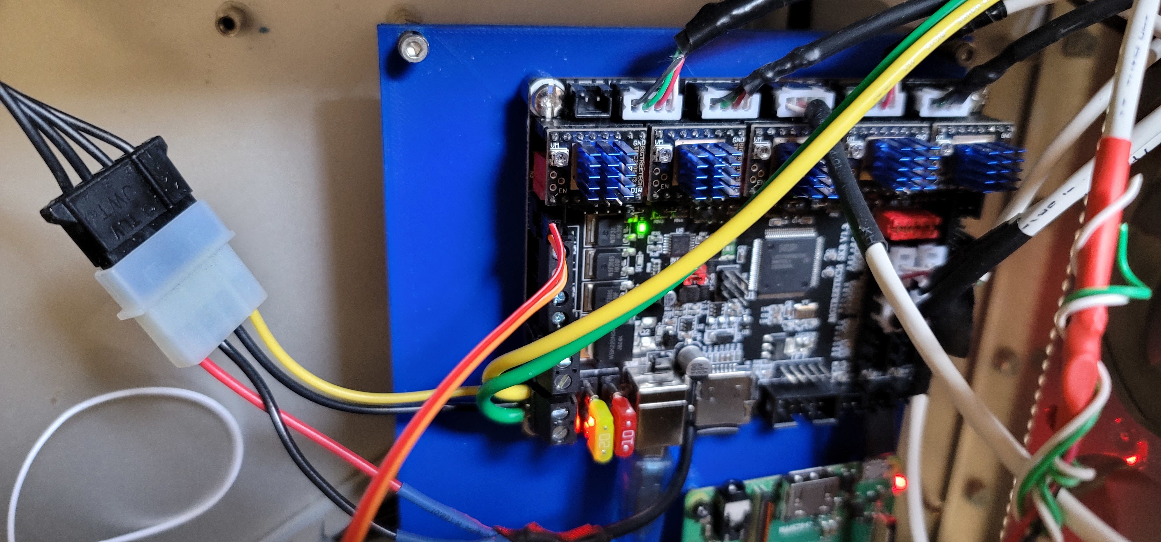
Eureka! Soldered in the back of the board at the second mosfet as Mike suggested and now pwm signal to the laser i working correctly!
Now is only matter of tuning and learning! Thank you again for all the support!
Glad you got it working. Just a note of caution - be careful how you handle that wire because it is directly attached to the MCU output pin (no buffers) and if you inadvertently apply any current to it it will probably toast the MCU (this is one reason why the opto-isolator approach was IMHO the preferred option.)
