Needle Cutter on LR4 Upgrade

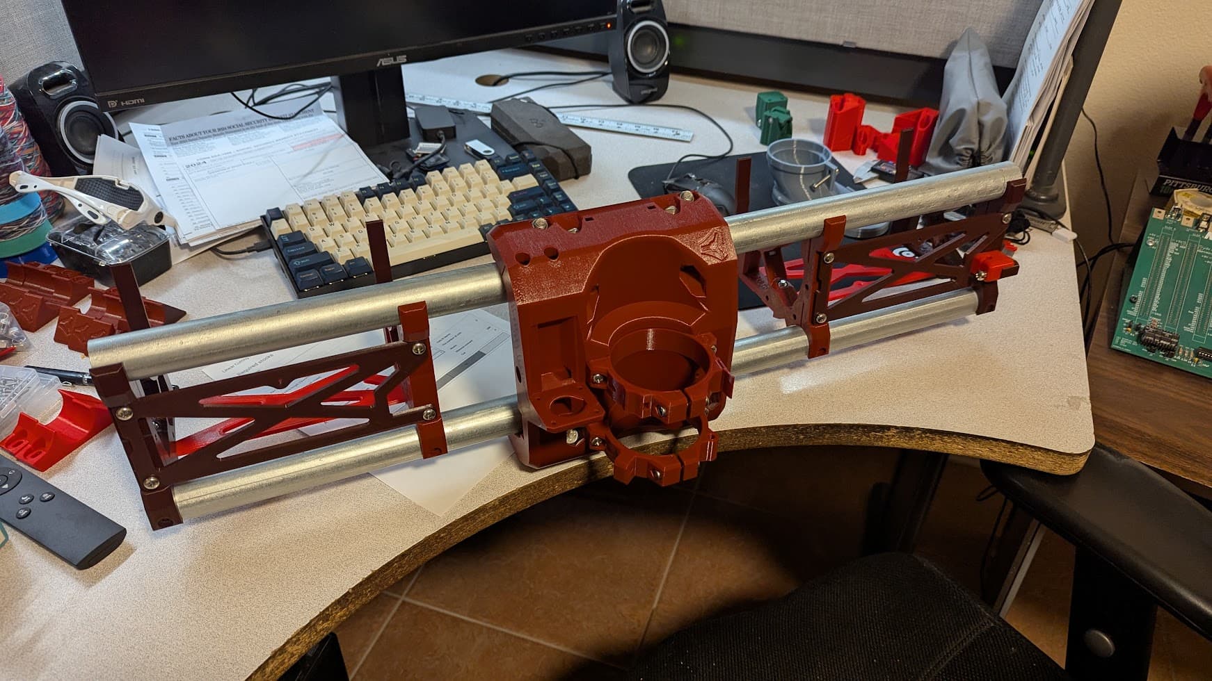
This post primarily focuses on the needle cutter, as the upgrade from LR3 to LR4 went very smoothly. I did encounter a minor issue with both the Y-axis pulleys slipping a few days apart, but nothing that a little Loctite couldn’t fix. But I digress!


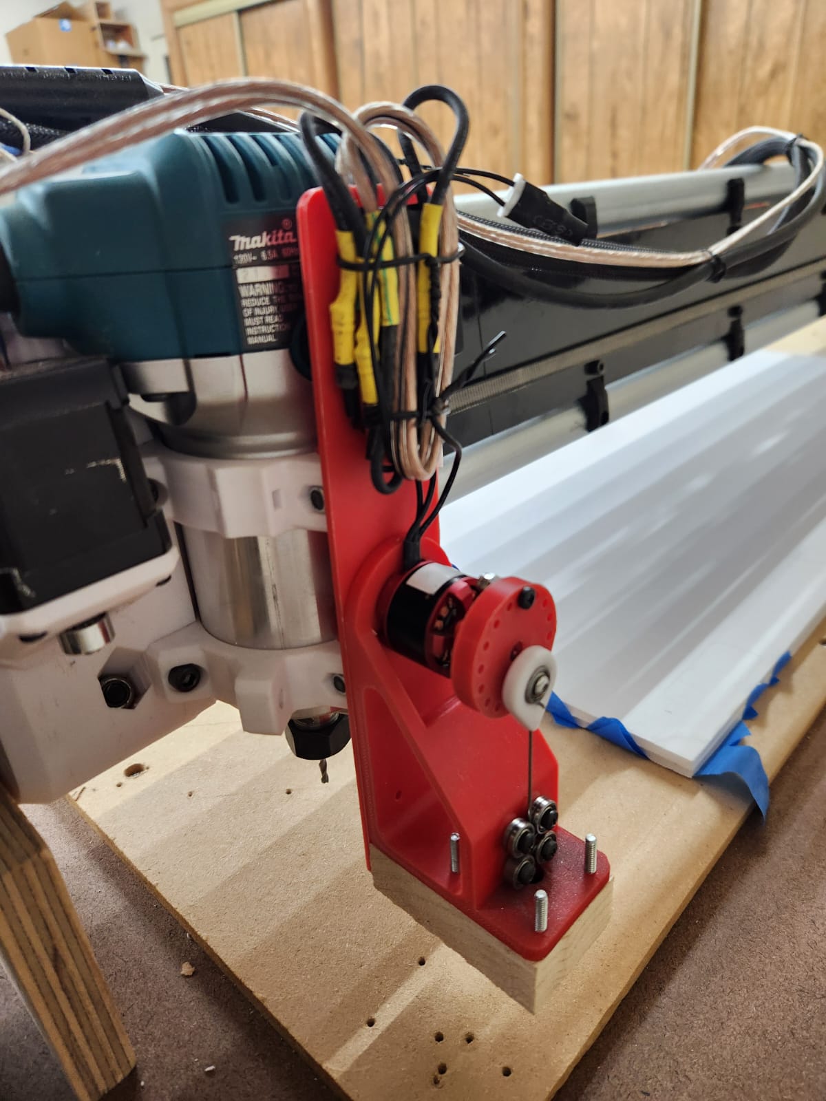
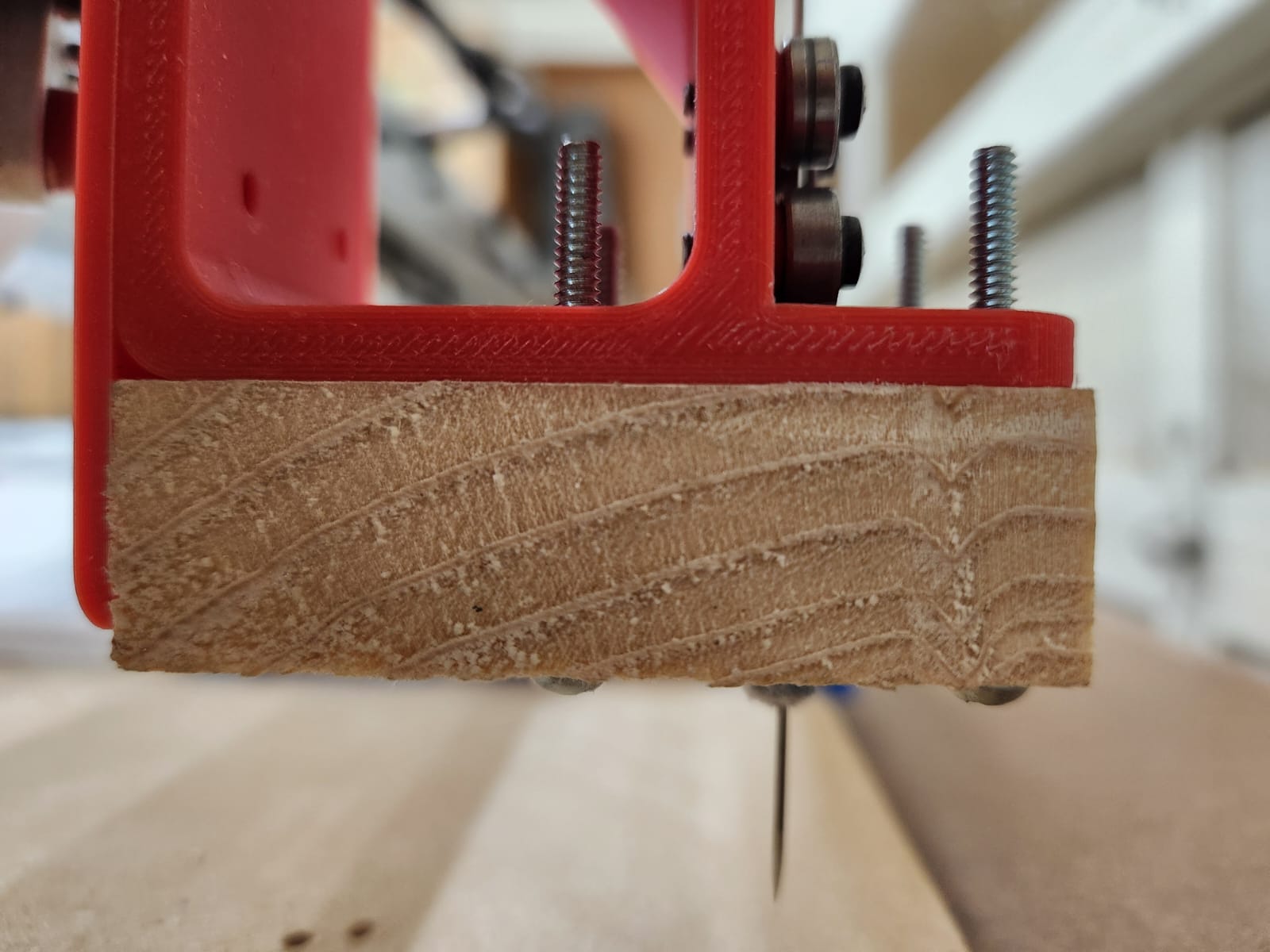
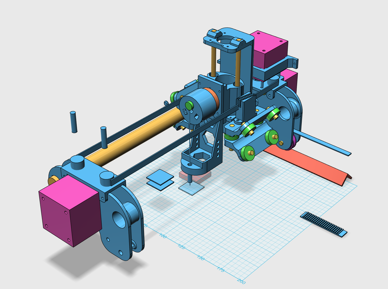
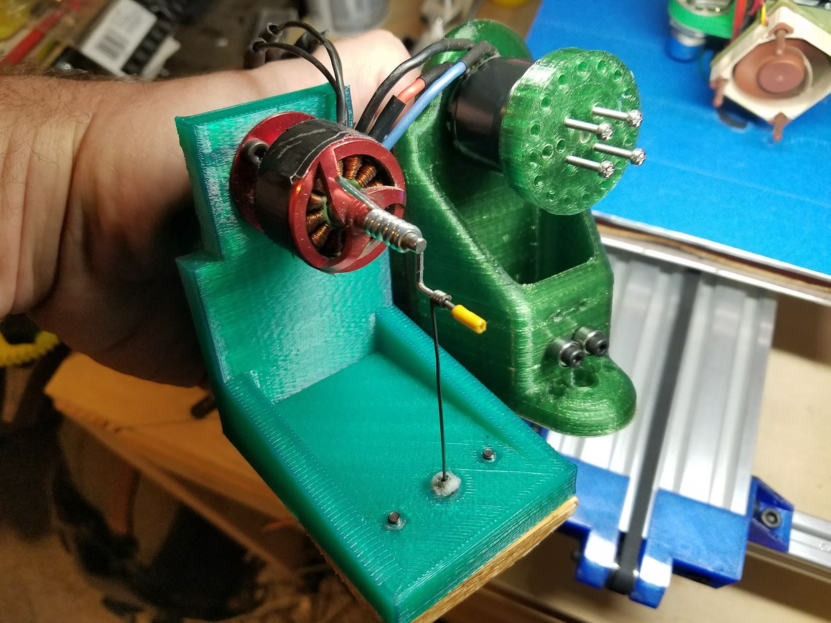
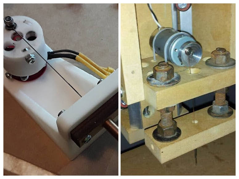
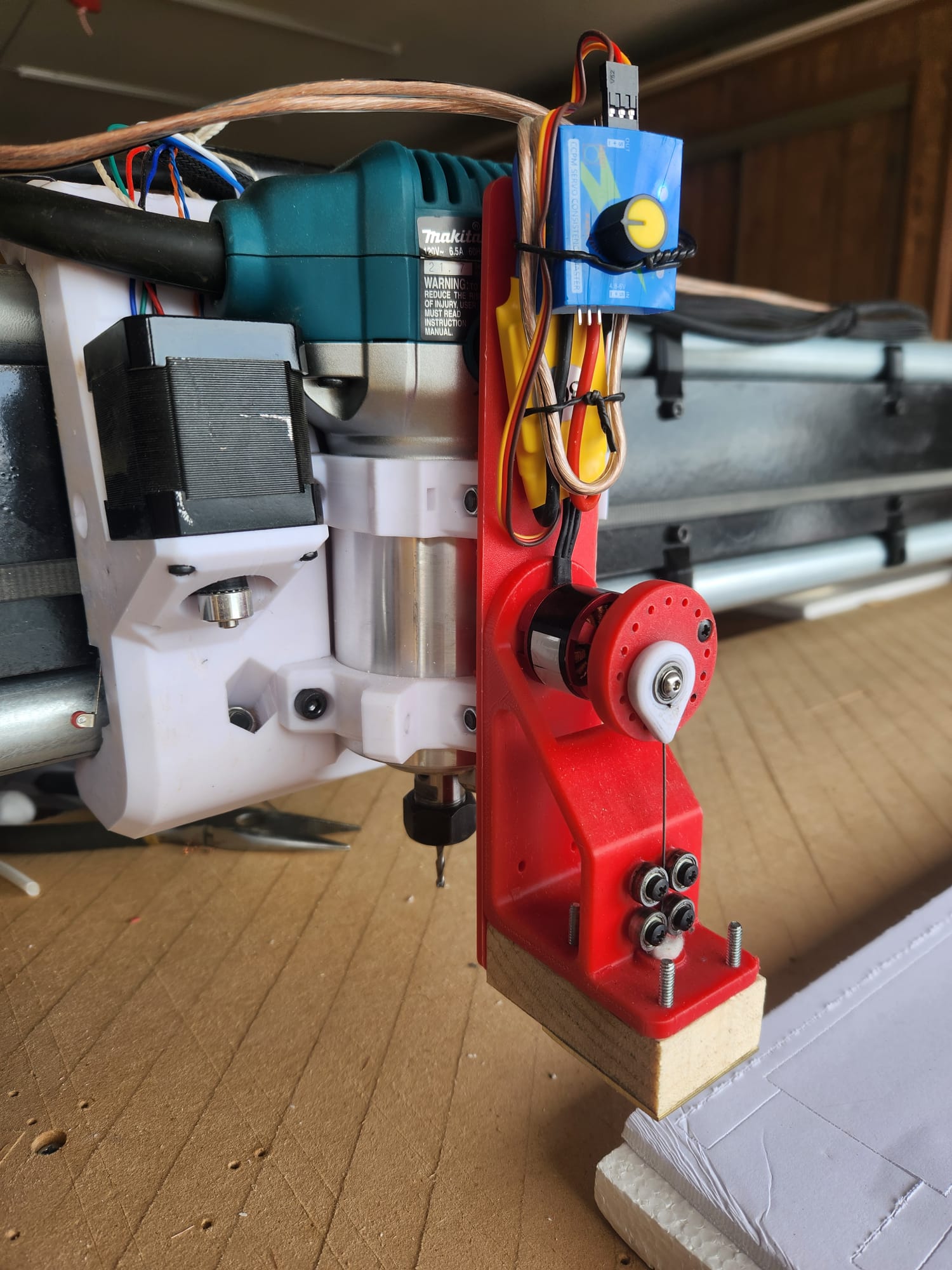
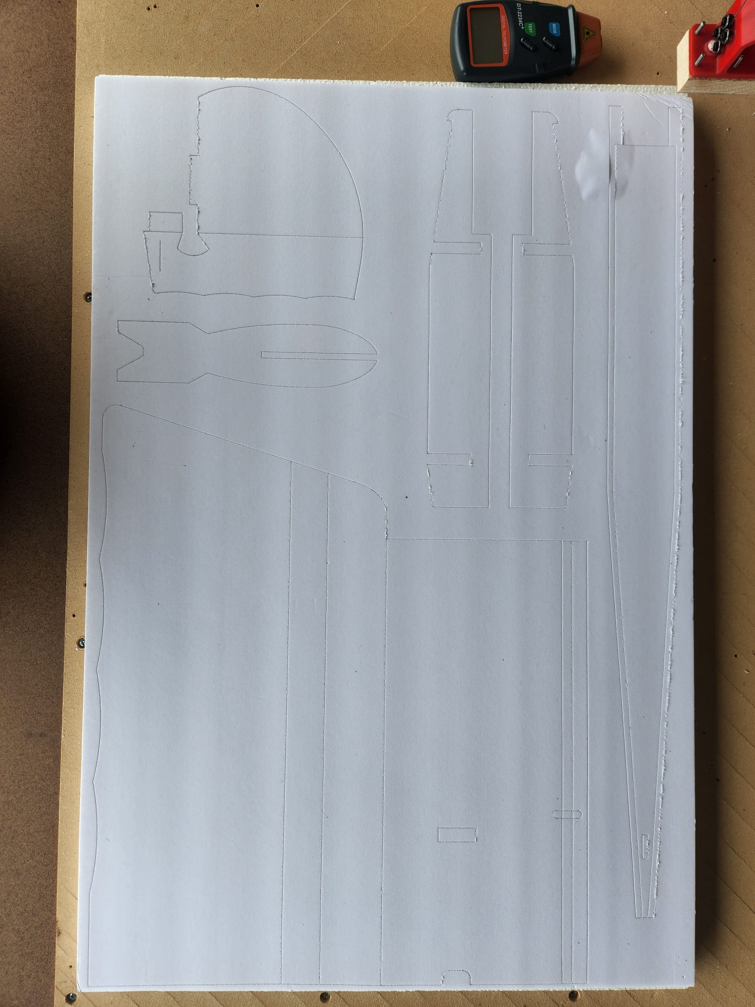
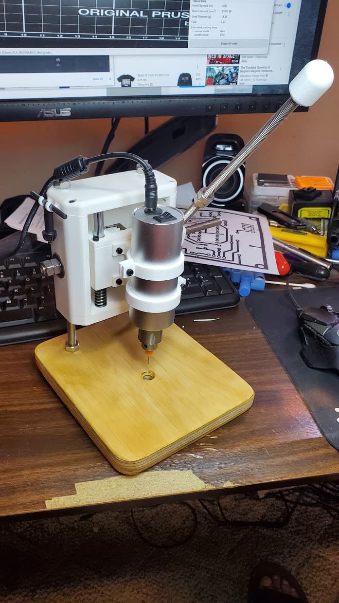
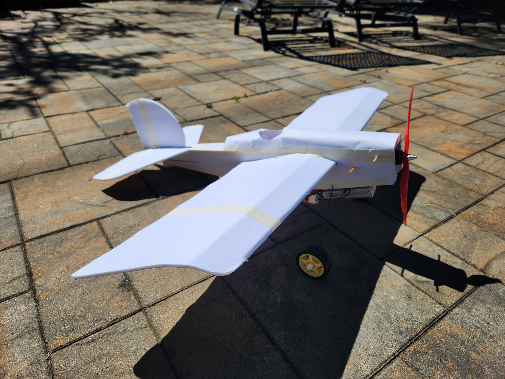
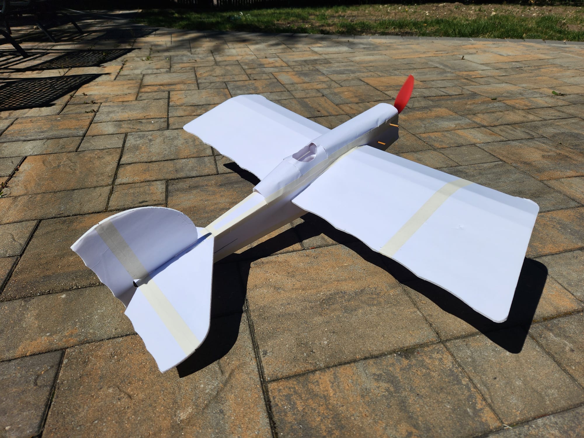
For the needle cutter, I mostly used the @jhitesma design, with a few modifications to suit the hardware I had on hand. Specifically, I used a 1mm steel wire (cable support from a Voron build), motors from a drone, some old bearings, and an ESC with a knob to control the speed (ESC on Amazon). The rest of the components are 3D printed in ABS. The setup worked quite well, and I was able to cut out a FliteTest Storch plane in about 2 hours, broken up into 20-25 minute sessions to allow the needle to cool down.

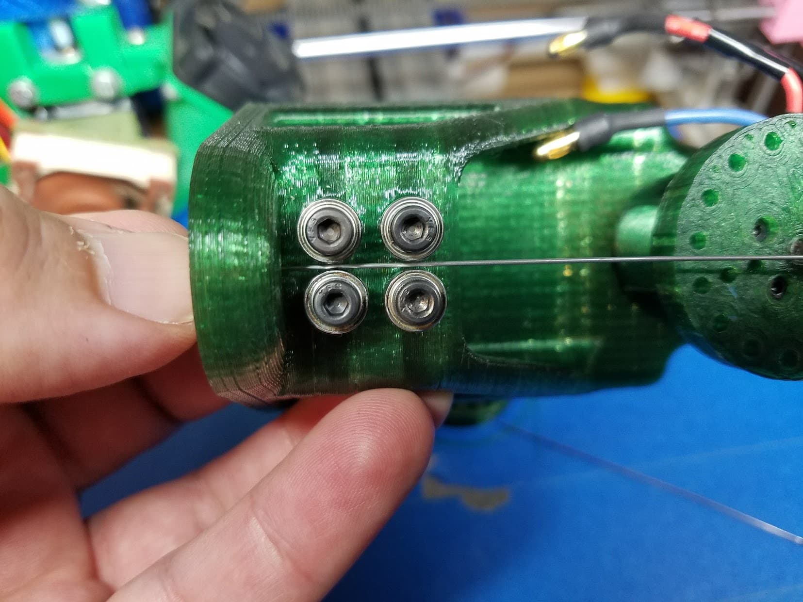
The setup is powered by a 12V 920KV BLDC motor (Motor on Amazon) that spins a flywheel at around 4000 RPM. I used a feed rate of 300 mm/min, with the needle mounted about 7mm from the center. I would like to cut the process time in half i.e. push the machine closer to a 600 mm/min feed rate.

I’m looking for guidance on improving the performance of the needle cutter. Here are some thoughts I had:

  1. Motor Load and ESC Performance:
  • I’m using a 2212 920KV motor, and I’ve noticed that the motor slows down when it engages with the material (Dollar Tree foam board). Is this normal due to the increased load? The ESC throttles power when it reaches a temperature threshold, but it’s difficult to tell if I’m hitting that limit. Any recommendations for a better ESC or motor setup?
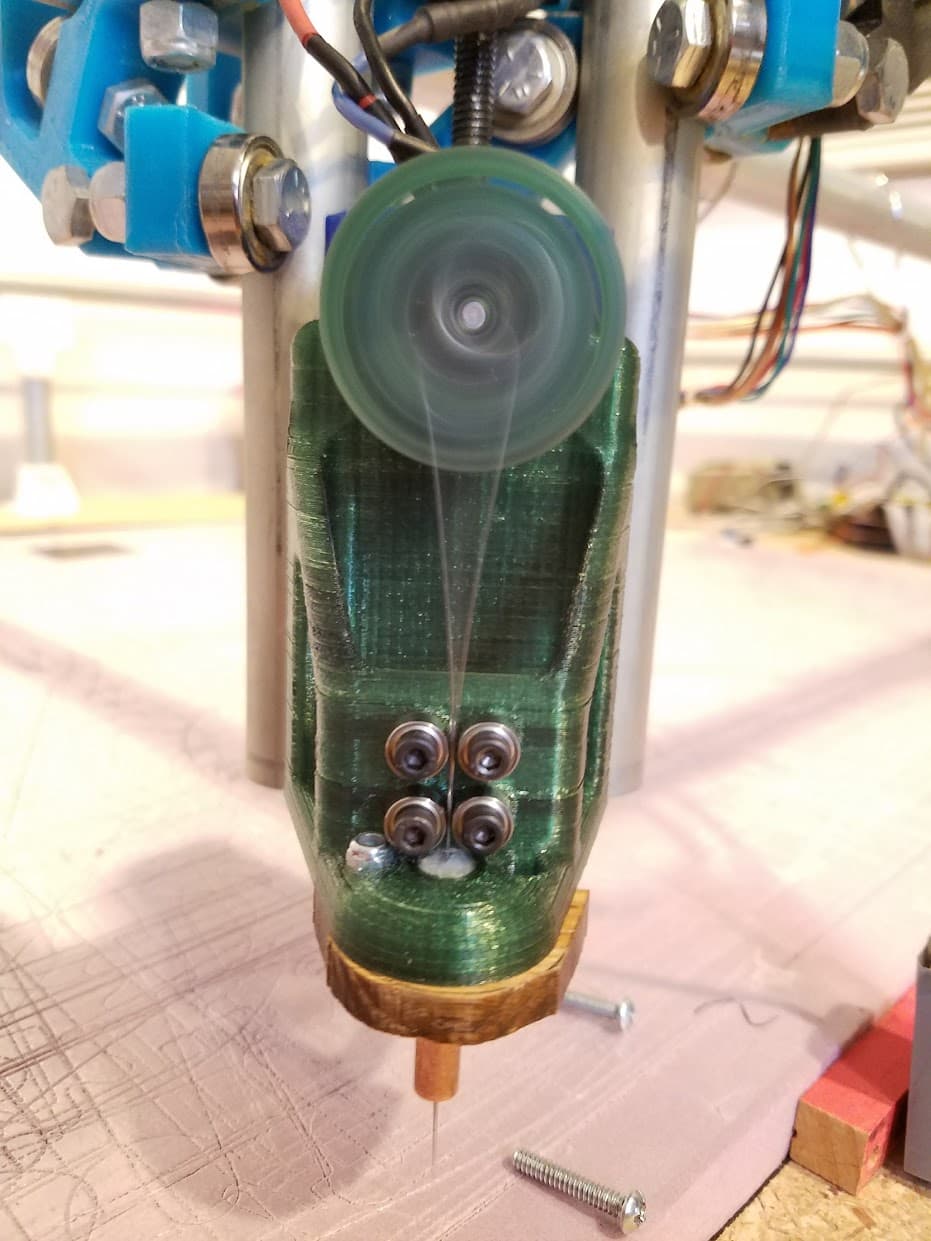
  1. Reducing Flywheel Moment of Inertia:
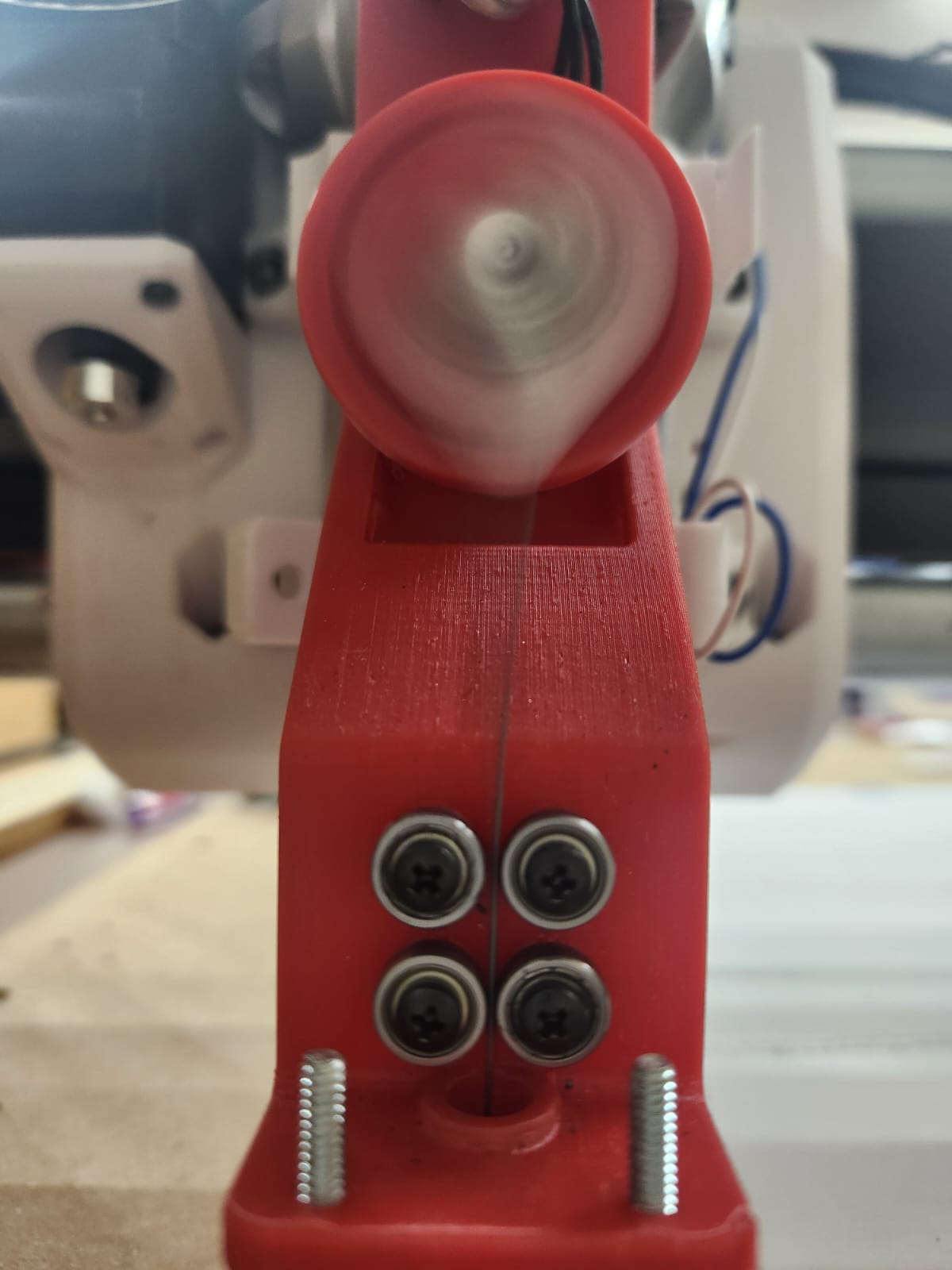
  • I’m considering reducing the moment of inertia of the flywheel by moving the bearing holding the needle closer to the center. The current motor shaft size is around 8mm, and with a radius of 4mm, the closest I could mount the needle was 7mm from the center. Since the foam board is only 5-6mm thick, I don’t really need 2x7mm (14mm) of travel. Is there a way to mount the needle closer to the center, or would it not help much even if I manage to do so?
  1. Bearing Size:
  • I’m currently using a 10mm OD bearing (Bearing on Amazon) for the needle. I have a suspicion that it is generating a lot of noise which can’t be good. Do you have any recommendations for a different size or a better alternative?
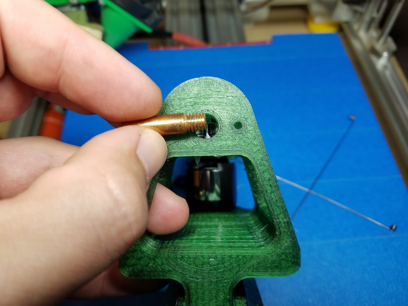
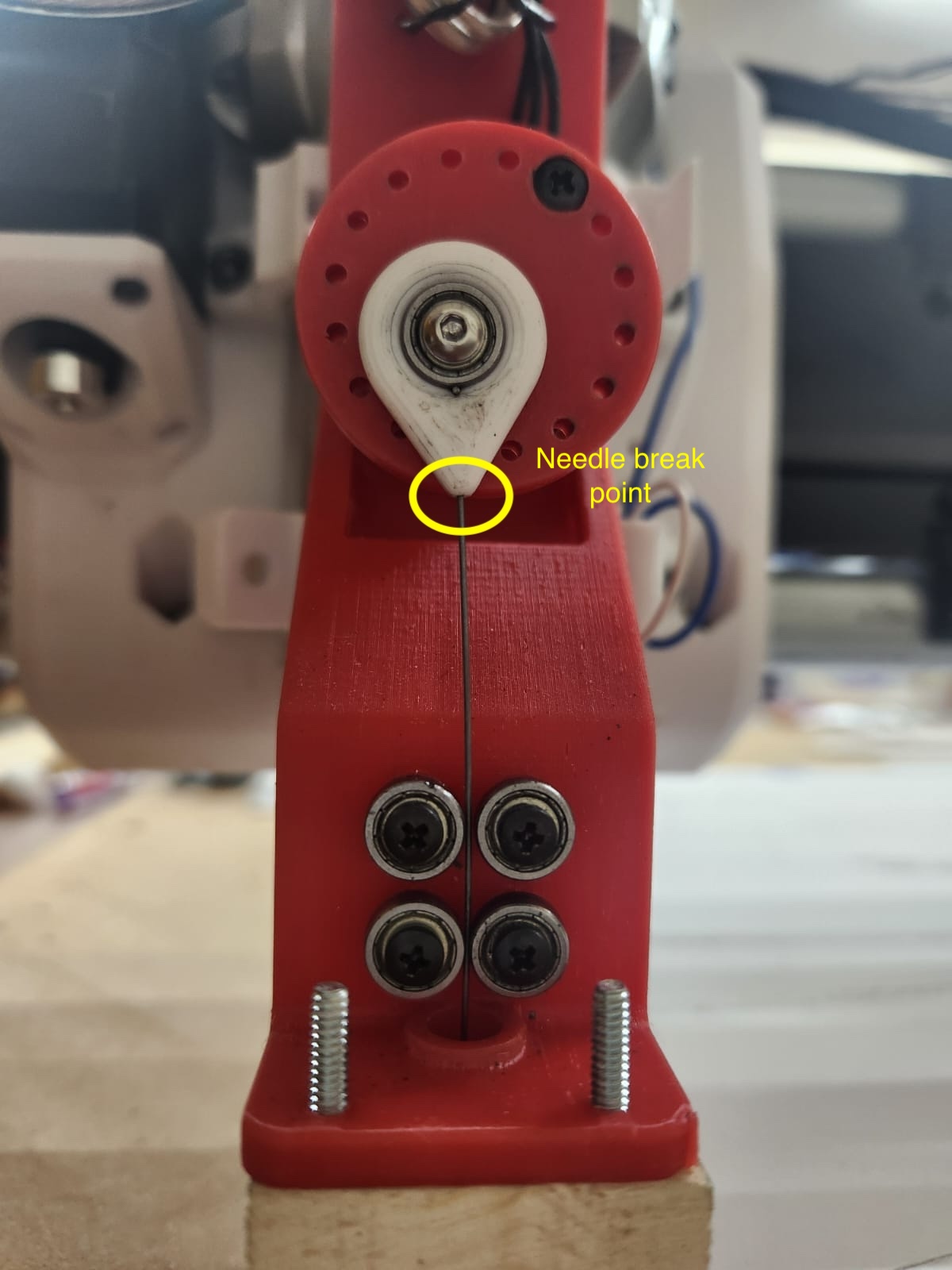
  1. Wire Thickness:
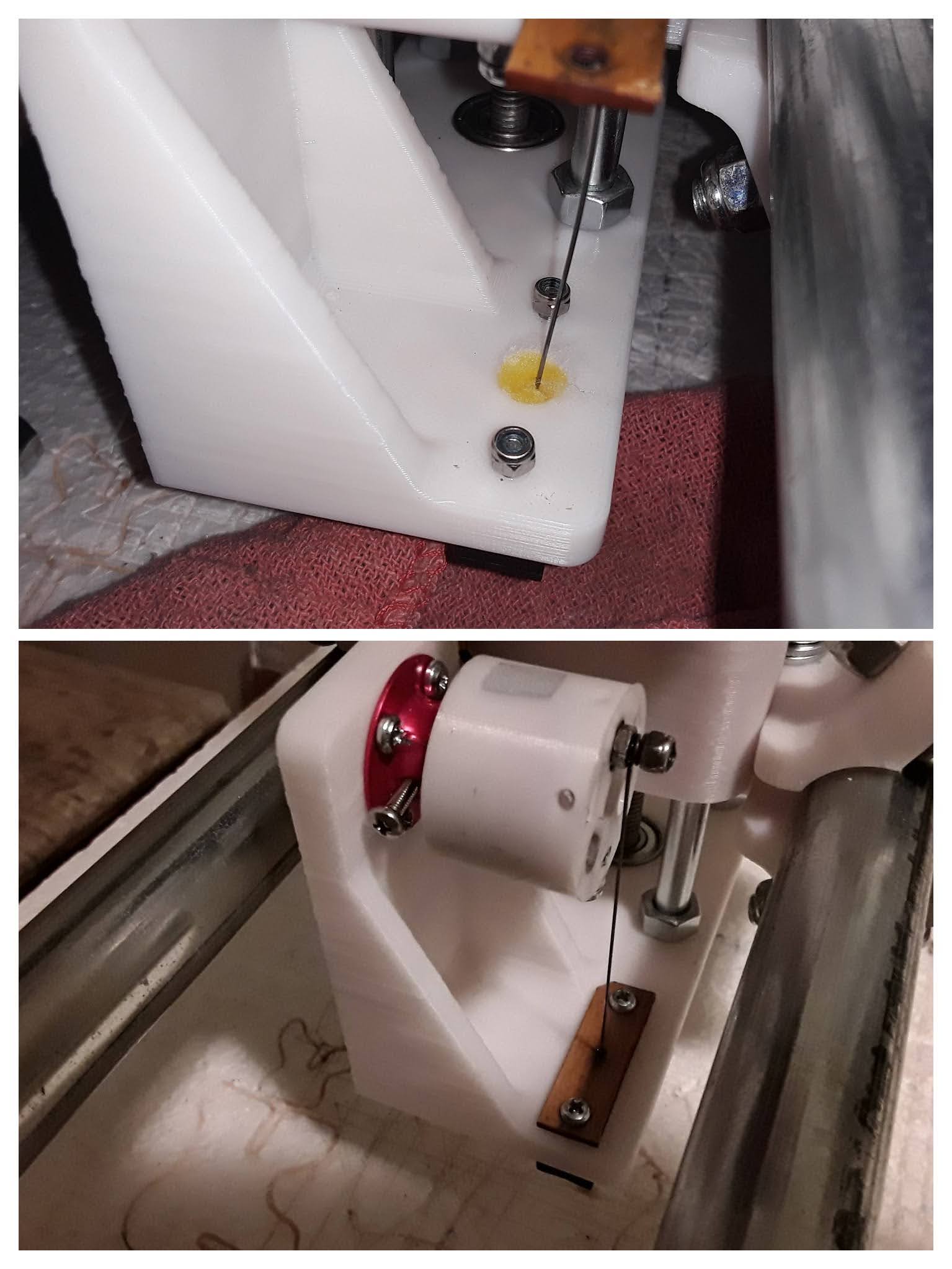
  • I’m using a 1mm thick steel wire, and I’m wondering if that’s causing too much friction with the MIG tip. The needle moves freely by hand, but might a thinner wire reduce friction and improve performance?
  1. Lubrication:
  • Would adding lubricant to the eccentric bearing or MIG tip help or hinder performance? This setup is high-speed rather than heavy-load, so I’m concerned that lubricant could introduce drag, especially given the small clearance in the guide. What are your thoughts?
  1. Heat Management:
  • The needle and sleeve heat up quite a bit during use. I’m considering soldering a metal plate to the MIG tip to help dissipate the heat. The plastic parts are insulated by the wooden block, but I’m not sure if this modification will help the performance.
  1. Needle Retraction:
  • I’ve read that the needle should fully retract inside the guide during the upstroke. Does this actually help in any way?

Let me know if you have any suggestions or advice on these points. Thanks in advance for your help!

6 Likes

That looks really good. I played with my foam ripper for a while and came to some conclusions.

I tried removing the guide bearings to reduce the friction on the wire but that caused excessive wear in the MIG tip. I tried a lighter flywheel and that did help

The problem is heat buildup so adding radiators should help, also spending time getting the flywheel balanced pays off. The wire size is pretty much dictated by the MIG nozzle.

I think lub will just get all over the workpiece.

Having the needle supported as it reverses direction would, I think, be a good thing so tuning your stroke to the workpiece might help but maybe too little clearance between the top of the workpiece and the tip at the top of the stroke might cause problems as the needle warms up and liquid foam sticks to it, it might depend on how rigidly the foam is held.

I could never find a set of grooved bearings. :slightly_frowning_face:

/my 2p worth.

2 Likes

I have just checked our microwave cooker… short youtube video

You can just make out a weak router signal in my kitchen…and then the microwave splurges all over the upper channels…

oops…posted this on the wrong thread…sorry

I should really try this. This would be great project for the spring/summer for me. I have all the parts for it.

1 Like

I had a lot of heat issues with my first attempts at a needle cutter. The bearings were one step towards helping with that by guiding the wire before it gets into the tip so there was less friction in the tip.

Size of wire does make a difference - it needs to be a loose fit in the tip…but I would size the tip to the wire rather than the wire to the tip. It looks like I used 0.62mm/0.025" - so almost half the size of yours. The wire does flex and that does create heat - having thinner wire requires less work to flex so less heat and stress. I would definitely look at trying thinner wire (and possibly a different sized MIG tip too then)

I did see less heat with a inflation needle like used on soccer/basket/volley balls. But it also wore out very quickly due to how thin the needle material is.

I do use a few drops of light oil on mine - I actually stuff a bit of cotton ball into the top of the wooden insulator and put it on there. That helps quite a bit with heat and if you’re not too heavy handed with the oil it doesn’t make a mess.

The needle retracting all the way did also seem to make a difference - though I’m not entirely sure why. One theory is that it lets the needle pass more heat into the tip to be soaked away - vs. needle that never goes into the tip only gets air cooling.

The biggie for me was speed - just guessing the speed based on the motor KV and throttle proved highly problematic. ESC’s aren’t usually linear and without knowing the curve on their throttle it’s impossible to know what kind of RPM you’ll actually get at what speed setting. I picked up a cheap $15 optical tachometer and found I was running almost twice as fast as I thought I was - once I got the speed under control I had a lot fewer issues with heat and needle failure.

Once I had it dialed in I was able to cut continuously with no heat issues. I regularly would cut 2-3 planes worth of material (6-10 sheets of foam) back to back - just needing to occasionally add a drop of oil to the cotton ball and the MIG tip would get warm - but not so hot I couldn’t touch it.

All the bearings I used came out of old motors. With my flying “skills” and joy of experimentation I had a habit of bending shafts on motors rather quickly and wound up with a sizable pile of unusable motors I scavenged for bearings to use on other projects.

I can’t quite tell from your photos - but it looks like your MIG tip is mostly up inside the wooden insulator.

I think you may actually be using the same motor I did on my first cutter - with a crankshaft before I switched to the flywheel/bearing…I think it came from one of the early Flite Test power packs - note you can see the bit of cotton stuck into the top of the frame around the needle in this shot:

On the revized cutter I actually made that hole even larger to fit more cotton in there so I didn’t have to oil it quite as frequently:

Here’s a shot of the later cutter where you can see the cotton as well:

That shot also shows the deflection of the needle really well. It’s hard to tell but the top two bearings are slightly further apart - the needle should ride on one when going down and the other when coming up. But the two lower bearings are close enough the needle rides on both in both directions. That makes sure that the needle is already moving vertically with minimal side deflection by the time it gets into the MIG tip which acts as the final guide.

Here’s a closeup of the bearings:

I’m actually getting ready to do a new design for the LR4 soon. I don’t have room for my old MPCNC at my new house so after I use it to cut the plates for a new LR4 it will be coming apart and donating parts to finish the LR4:

Just put that much together last night as a test fit :smiley: Will be fairly small for a LR - 21"x31" cutting area (might go bigger on the longer axis.) Instead of a dedicated table it will have to share my workbench until I build a new shop. But…I also have to rebuild my workbench to make it a little deeper and a lot more stable / flat. (my current workbench I built in 1999 in an afternoon as a temporary solution to the lack of work surfaces in the garage I was sharing with two roommates where all three of us had multiple ongoing vehicle projects. It spent the last 17 years in a shed and I was excited about finally getting it out and using it as a bench again…only to find that it wasn’t nearly in the kind of condition I thought it was. So now I have an excuse to upgrade!)

I’m still debating if I want to add the needle cutter in addition to a router - or make the needle cutter replace the router. For my own use I may need to make the needle cutter replace the router to maintain the ability to cut edge to edge on 20"x30" foam sheets. Though - I don’t do much flying anymore so expect to cut wood/plastic/metal more than foam on this machine. My old machine was really too big for much more than foam so I’m excited about having one that’s stiffer and can do tougher materials.

2 Likes

My heart leaped when I saw your needle cutter. What a nice build! I’ve been away (retired :wink:) from the “needle cutter business” for a few years but thankfully documented my last efforts in a couple of forums. So I can share pretty accurately my experiences with this fun little piece of machinery.

Here’s my last needle cutter in action and running on my LowRider-inspired FoamRipper. It’s running at about 8000 RPM (no load) on the motor RPMs and at 610 mm/min feedrate. You can hear you does lose a few RPMs as the motor goes under load when the needle pierces the foam and starts the cut…

I never used the multi-bearing pre-guide system that many of the guys use… and they were far more actively cutting planes than I was. Personally, I was never “bothered” by the bending of the needle… piano/music wire is “spring steel” after all and designed to bend. But I tried many different things – some pretty novel; i.e. mousetrap and clothespin parts – over the years to get near-straight-line motion of the needle in the main guide to reduce friction and heat…

but ultimately kept coming back to my original concept.

My latest needle cutter in action above featured an over-the-bell slip-on “flywheel” that balanced and ran very smoothly. The needle is 0.025" piano wire and there is an “oil well” for needle lubrication between the upper and lower stacks of the laser-cut wooden needle guide.

This needle cutter’s build is detailed starting with this post and a number of my following posts in that thread…

Your needle cutter is operating at about half speed compared to mine. I’ve always recommended about a cutter RPMs to feedrate ratio of ~10:1… which gives clean cuts in DTFB with the paper on. Therefore I set my cutter RPM to 8000 or so to account for the drop when it goes under load and then set my feedrate to 600-700 mm/minute… as in the first video above.

Your needle wire is pretty heavy as well… I’ve always used 0.025" piano wire vs yours at 0.039"? I used 0.025" K&S piano wire in a IIRC 0.035" Mig welding tip. Complete retraction of the needle into the tip isn’t critical IMO… it just needs to safely clear the top of the foam by a few millimeters or so. It’s probably better to set the tip of the HOT needle guide away from the material 5mm - 10mm anyway… to avoid any radiant melting of the foam and/or to accommodate any non-flatness of the surface of the material.

I’ll stop here. I think I saw that Jason (@jhitesma ) has already responded so you are in good hands to get further assistance. I also just remembered that I have a fairly lengthy FoamRipper thread here on the V1E forum that details most of this as well.

Good luck! I think you’re definitely on the right track here with your needle cutter build.

– David

3 Likes

Be sure to add the cotton ball and mineral oil. It made a huge difference for me.

3 Likes

Thanks, everyone, for your suggestions! After implementing them, the operation looks much more promising now.

Changes Made:

  • Switched to a thinner wire (0.025") along with the appropriate MIG tip.
  • Added a small well to hold cotton infused with mineral oil.
  • Reduced the gap between the final two bearings just before the wire enters the MIG guide.
  • Moved the needle rotation point closer to the center of the wheel (5.5mm), resulting in about 11mm of travel.
  • Resized the needle length so that it barely retracts into the MIG tip at its highest point.
  • Soldered a metal plate for better heat dissipation.

Results:

  • The needle remained cool throughout the 40-minute run, staying close to room temperature.

  • The rpm drop under load was significantly reduced—idle rpm was around 7600, and under load, it only dropped to ~7100. For some reason, when I tried touching 8000 rpm, the motor locked up. I suspect its the ESC.

  • I was able to increase the feed rate to 480 mm/min. At 600 mm/min, however, the needle broke after about 20 minutes, which requires further investigation.

  • There was a noticeable reduction in noise.

Overall, the performance has improved significantly, though there are still some aspects to refine.

For the next steps, I am planning to replace the ESC with a more premium version :slightly_smiling_face:. Will try to push the rpm to 8000 and the feed rate to 600 over the weekend :crossed_fingers:

6 Likes

Super hyped to hear the suggestions helped!

ESC has always been a weak point IMHO. I used ESC’s designed for multirotors instead of fixed wing since they tend to have a straighter throttle curve. But they’re still not ideal.

Some custom ESC firmware had provisions for constant speed modes but I was never able to get it to work. Theoretically they should be able to be set to maintain a constant RPM as load changes…but since it wasn’t really needed for most uses I don’t think it was ever fully implemented.

I actually spoke to the guy who did the firmware for some of the early multirotor ESC (simonk iirc?) about doing a custom firmware build that would just go to a fixed RPM and hold it. He basically said it was possible and not that hard to do…but he didn’t have the time to devote to it.

I’ve actually been learning some assembly language programming the last few years - but I’m still no where near being able to hack that code.

1 Like

So, I did end up trying a different ESC (pictured below) and not only was I able to push the machine to 600 mm/min easily, there was no random erratic behavior or the motor locking up at higher speeds. The RPM drop was also less than the previous ESC I was using.

. I guess this one is a keeper!

Another slightly more generic thing I tried was the to bump up the speed of travel moves which are otherwise limited to feed rates with the free version of F360. A little bit of prompt engineering with ChatGPT produced a python script that can post process the gcode to detect and change the travel moves to a specified rate.

The needle did not break this time and there was absolutely no heat build up. Now I just have to go through a few foam sheets and see how durable this whole thing it. Here is the sheet I just finished (may have to zoom in to see the cuts).

@jhitesma Congrats on diving into assembly language! I’ve used LLMs with C and Python, and they’ve definitely helped speed up development. I’d be curious to see how they handle assembly— would you be interested in giving it a try?

5 Likes

I see a Simple Scout in your future. I’m glad you’ve got it working much better now.

1 Like

This is cool! I may need to make one just because… Have you published plans anywhere?

Glad to hear it’s working well. Once I got mine dialed in I almost never broke needles. I even successfully cut carboard a few times and didn’t break the needle.

Oh and love the simple scout, great plane!

I’ve been trying to learn assembly since the 80’s…finally starting to get my head around things this time - but it’s still VERY slow going.

LLM’s with assembly aren’t great yet in my experience. They just haven’t been trained on much assembly code. But it also depends on the system you’re dealing with. For 8052 based systems I’ve seen them make almost usable code, but I’ve mostly been playing with the RCA 1802 and for that LLM’s are completely useless. For things like modern ARM chips in ESC’s…I suspect since most people use higher level languages there isn’t enough code out there for the LLM’s to have trained well much like the 1802.

I got kind of sucked down an 1802 rabbit hole the last few years…it’s an early 8 bit processor RCA made that has an interesting history and a really unusual command set and register layout. A few years ago an unrelated mailing list I follow had a post from someone about a bunch of 1802’s showing up cheap at some surplus shop and suddenly all kinds of people were sharing stories about how the 1802 got them into computers back in the 70’s. I’ve always been interested in the old computers with lots of switches and lights and realized I could build an original ELF based on a Popular Electronics article from the mid 70’s.

That’s it in the middle. The Display is 2 hex digits and a single LED - the input is 8 toggle switches you use to directly program individual bits into memory. It’s a remarkably simple computer and very intimate way to program :exploding_head:

I always wanted to try programming something like that…and I wanted to learn wire wrap so this seemed like a fun project and definitely was. It’s very close to the original except I used a modern clock oscillator instead of the stock crystal, and I designed and 3D printed a frame and stand instead of the original wood strips. The other side is my favorite:

The other two computers in that first photo followed. On the left is an “1802 membership card” which is basically the same thing shrunk down to fit in an altoids tin and with a lot more memory and an eeprom so it can actually do useful things as soon as you power it up (Using a serial connection to a terminal to interact with it.) On the right is a VIP2K which is an homage to one of the more popular 1802 based computers - it has video output and a built in keyboard…but still fits in an altoids tin.

Now I’m working on a recreation of the ELF II which was an expanded commercial version of the original ELF:

I have the base system working great, and built a modern replacement for the original (and hard to find) CDP1861 video chip and got video working on it. Now I’m working on an expansion board that will give it serial I/O, the ability to read/write to tape, an EEPROM with a basic OS and a few other upgrades.

Sorry to get off track - hopefully it’s somewhat interesting at least, I haven’t really looked at ESC code for probably 5 years now. Once I have my LR4 working and start making a new needle cutter for it I’ll probably take a look at what’s been going on and maybe take a closer look at getting a governed speed option working.

2 Likes

Noted and makes sense.

That looks really neat. I’m not deeply into retro computing, but it’s fascinating to see how far we’ve come in just a few decades—from programming with toggle switches and LEDs to simply writing code in plain English and letting an LLM translate it (at least for some languages). Out of curiosity, I looked for a compiler that could generate a first draft of assembly code for the 1802, which could then be refined before assembling. I found lcc1802, an ANSI C compiler, and CPD1802 BASIC, which directly converts BASIC statements into 1802 machine code

Wow! That wiring is intense—debugging it must have been a challenge! :wink: I see another project here for LR4/MPCNC if you are interested and have some time. I have done small PCBs with MPCNC in the past and once dialed in, it can produce impressively fine traces.

Your ELF II build is awesome! Getting the base system up and running and even making a modern replacement for the CDP1861 is seriously impressive. That expansion board sounds like a great upgrade—serial I/O, tape read/write, EEPROM, and a basic OS? That’s gonna take it to a whole new level! Pls share when you have updates.

Yeah, both are out there - but…fairly limited. The issue is the resources on these old systems are just so limited and often so custom to each build that you almost have to work with the raw assembly to get anything very meaningful accomplished. That said there is a basic interpreter available but it’s very limited and can’t even handle floating point numbers. Someone recently made a pascal interpreter as well - but it’s still a work in progress.

Shockingly it actually worked first try! I really didn’t expect it but - being very methodical with a large printed schematic I checked repeatedly for each individual connection made it go fairly easily.

I also have a similar wire wrapped z80 based system a friend built in the 80’s and gave me after he saw my ELF - it doesn’t work and I’ve been working on debugging it. And that HAS been challenging since I’m not familiar with the system…it’s based off a design in a popular book from the era - but with custom modifications. So there’s no official schematic to refer to. I’m at the point where I’m pretty sure I know what part of the circuit is having the problem…just not having any luck finding the actual issue in that part of it.

As for PCB’s. I’ve done quite a few. Anymore with the Chinese fab firms so affordable and quick I like to just have them made…but when designing them initially it is nice to make them yourself sometimes.

I tried some milling but always found it too fiddly. I actually majored in photography back in the day so I found photoresist process really easy to pickup. A $11 roll of resist film off amazon is enough for hundreds of boards - the developer is easy to make with washing soda from the grocery store. I made a mini drill press (based on a design I found on Thingiverse but I added some improvements of my own) which made drilling the holes fairly easy:

The hardest part was learning to make good negatives - I struggled with my laser printer for awhile before giving and trying a cheap inkjet, which combined with paper designed for screenprinting worked great. I was able to get enough detail to work with larger SMD parts with minimal effort.

I used some scrap MDF and 3d printed spacers with an old contact printing frame to get really consistent and repeatable exposures:

After a few weeks I had it down to where I could go from a KiCAD design to a finished board in under an hour. I documented the process after I had it figured out over here: Etching PCB's at home - DIY STUFF - Look Mum No Computer Thingies

I did at one point experiment with using the laser on my MPCNC to directly “expose” the resist…but it was quicker and easier for me to use the traditional negative process at the time.

To be fair - I’m basically just a technician on this project following others who did the hard work of designing it all. The CDP1861 replacement was the work of 3 different people each working off the previous ones designs and improving it. I just had to assemble one - though it took me three tries to get it right with the super tiny SMD components it used! The expansion board is also something that’s already done and I’m just building my copy. The project along with the various expansions available are all up on github here: GitHub - awasson/AVI-ELF-II: The AVI ELF II is a reproduction of the 1802-based computer kit by Netronics Research and Development Limited. The AVI ELF II computer was reimagined by the late Ed Keefe (1964-2022) to maintain the aesthetic of the original ELF II, with additional onboard RAM and daughter cards for flexibility of keypad encoders and display drivers.

Once mine is done I may replace the 3d printed legs with some machined ones if my LR4 works as I hope it will :wink:

2 Likes

Hi there! There are a lot of info and pointers to the 3d models here and in this thread. The documentation is more elaborate than I can ever generate. But after going through it, if you still think you need my version of the 3d printed parts which are specific to the hardware I had on hand, let me know and I will upload it to Thingiverse. Thx.

3 Likes

Tried a few test flights over the weekend.


The flying portion was a disaster :laughing:, but it was still a lot of fun. The landing gear is definitely the weak point—especially when keeping the plane in the air is a challenge. Luckily, 3D printing to the rescue! I have some ideas to make it more durable and handle rough landings better.

4 Likes

I’m glad you got to fly it. Foamboard is cheap, which is why I like the Flitetest planes so much!

2 Likes