Hi All ,
The forums are really helpful and filled with a lot of information but after looking at it for past 2 to 3 days I am very confused regarding how to wire up a SKR 1.4 Turbo board with 2099 stepper driver to a lowrider V2 (I doubt if it matter if its V2 or V3). I have described my issue below and my interpretation for possible solution so far.
1. Issue
I want to connect the X stepper , two Y steppers and two Z- steppers separately to all the five stepper ports in SKR 1.4 Turbo
Possible Solution
X → X Stepper
Y → Y1 Stepper
Z → Z1 Stepper
E0 → Y2 Stepper
E1 → Z2 Stepper
2. Issue
I want to have a Single Endstop on X-axis, Dual Endstops on the Y as well as the Z-axis and a Touch Probe
Possible Solution
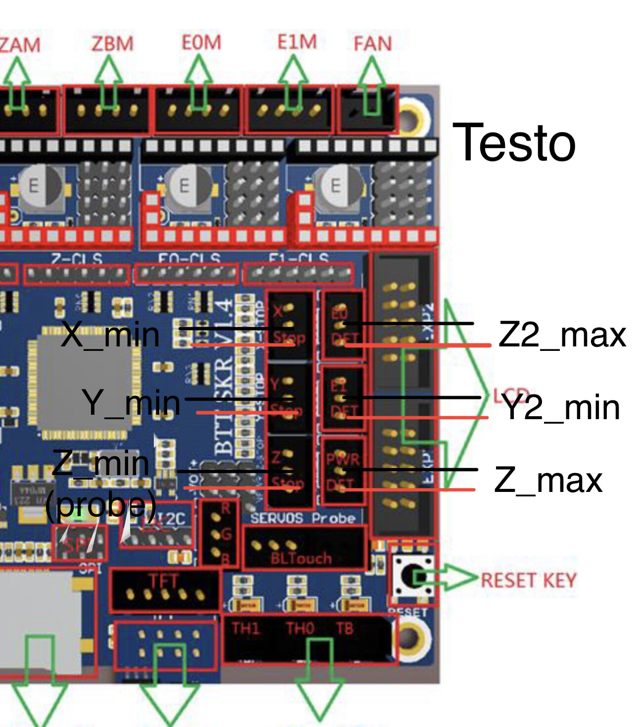
The SKR 1.4T has the following Endstop Options X-Stop, Y-Stop, Z-Stop, E0-Det, E1-Det, Pwr-Det
X-Stop → X EndStop (X_MIN)
Y-Stop → Y1 EndStop (Y_MIN)
Z-Stop → Touch Probe
E0-Det → Z2 EndStop (Z_MIN)
E1-Det → Y2 EndStop (Y_MAX)
Pwr-Det → Z1 EndStop (Z_MAX)
3. Issue
I want to use the basic LCD (not the fancy TFT) and have the firmware move the steppers and respond to the endstops as expected
Possible Solution
compile and install “V1CNC_SkrTurbo_DualLR_2209-2.1.1.zip” as is and it should just work fine.
Please let me know if I am correct with my assumed solution or am I missing anything or anything else I should be taking care of .
Thanks in advance
I have no personal experience with this board, but I took a look at the Marlin files. The display is set up for the REPRAP_DISCOUNT_FULL_GRAPHIC_SMART_CONTROLLER. This is the LCD that V1/Ryan sells, and it is also the one that comes with many of the Ramps kits sold on Amazon.
I also looked at the endstops. It appears that E0-Det, E1-Det and Pwr-Det, are treated as X_Max, Y_Max, and Z_Max, so you are set there.
Thanks for replying. That’s the exact display I have so I suppose that’s one thing solved.
If I understand the endstop setup correctly then X and Y are quite straightforward. For Z , the axis is moved until Z1-Stepper touches Z-Max and Z2-Stepper touches X-Max. This should square all the axis. Then to use the the touch probe, lower the Z-axis until Z-Min in triggered.
The other question I have is do I have to explicitly define somewhere in the configuration_adv.h that I am using two stepper on Y and two stepper on the Z-axis
Please let me know if I understand it correctly. And thanks again for assist.
Based on posts on the forum, it is a bit tricky to get the setting right for dual steppers. Fortunately, the V1 firmware you reference is already set up that way. All the versions of the V1 maintained firmware that have LR in the title are configured for dual steppers and dual endstops. The firmware should work unmodified.
If you really want to know how to set up the dual steppers, you can use a tool like Meld and compare a serial version of the firmware with dual LR version.
I thought So, also in the configuration.h file there are these two line
#define USER_DESC_4 “Probe Z min” #define USER_GCODE_4 “G38.2 Z0”
I looked up the G38.2 in marlin documentation and I think “G38.2 Z0” means keep moving towards Z 0 until you touch the probe.
But what I don’t understand is when it touches the probe it assigns that location as Z = 0mm. I didn’t ask this question in the original post as I am not there yet.
I don’t have a Lowrider. I have MPCNC Primo which uses G28 for a touch plate. Recently I enabled probing (G38) on my Primo and played with it some. In my limited play, Z0 does two things. First it defines the direction to probe relative to your current position. Second, it defines the limit of the probe. If you were to hit Z=0 before hitting the touch plate, probing would stop and it would generate an error.
If you probe directly after homing Z, then you will never reach Z=0 (and therefore never generate an error) since the position that is established for the Z when it is homed is greater than the possible movement of the Z axis. But, according to a forum post, you can have an issue if you use the touch plate to establish Z=0 as the top of the stock, but a subsequent probing (say after a bit change or surfacing the stock), could go below Z=0. As mentioned above, I’m inexperience with G38.2 probing, but I believe you can solve the problem by using some negative value instead of Z0 in the probing command.
But what I don’t understand is when it touches the probe it assigns that location as Z = 0mm
Probing does not assign any new value for Z. You must use a G92 in in whatever script you use for your touch plate to assign the height you want. In fact, when you hit the touch plate, you don’t want to assign Z=0, but instead the height of the touch plate (since your stock is that distance below the touch plate). If you purchased your touch plate from V1, the bit will be at Z=0.5mm above the stock, so that is what you should assign. I’m sure there are multiple scripts on the forum and probably in the Lowrider documentation for using the touch plate on a Lowrider.
If I don’t want to modify anything in the configuration file then the endstops should be Normally Open(NO) type , right? Because those are the ones I have with me.
All V1 configured firmware is set up for a Normally Closed switch between the stop pin and ground. Thos includes the community based firmware as well.
In order to use a Normally Open switch, you must reconfigure the firmware to trigger end stops on logic low. As is, they are configured to trigger on logic high.
The end stops have an internal pull up resistor that brings the end stop pin up to around +5V, or logic high when theu are not connected to ground. When you connect the pin to ground through a low impedance circuit (a closed switch) it brings the voltage to logic low.
If you use a normally open switch, then the “rest” state of the circuit will be logic high, and the triggered state will be low, this is the opposite of what the firmware expects.
The touch plate (Z Min, on the dual LR firmware) is configured this way for a nkrmally open switch, since the switch in this case is the clip and the touch plate, so the toich plate configuration as logic low triggered can be copied to the other switches and the firmware can be recompiled. While you are at it, you may want to set the bed size in the configuration.h file.
Thanks for the reply. I looked in the forums and it seems like the endstops are set up as NC as a safety precaution. I will see if i can find some limit switches which are NC if not then I will work on your suggestion.
Most of these microswitches have 3 terminals. Common, NO and NC. You want these pretty much anyway as they are the switch types that the printed plastic parts are designed for.
There was a recent “debate” on a forum topic about the benefits of the normally closed configuration of the switches. My takeaway is that, given the use of NEMA 17 steppers, there is little in the way of safety issues with a normally open configuration. If you want to use your switches, and if they don’t have three terminals as indicated by Dan, you can change to normally open by changing false to true in this section of configuration.h and recompiling using PlatformIO.
// Mechanical endstop with COM to ground and NC to Signal uses “false” here (most common setup). #define X_MIN_ENDSTOP_INVERTING false // Set to true to invert the logic of the endstop. #define Y_MIN_ENDSTOP_INVERTING false // Set to true to invert the logic of the endstop. #define Z_MIN_ENDSTOP_INVERTING true // false // Set to true to invert the logic of the endstop. #define I_MIN_ENDSTOP_INVERTING false // Set to true to invert the logic of the endstop. #define J_MIN_ENDSTOP_INVERTING false // Set to true to invert the logic of the endstop.
Personally, if I had NO switches, the deciding factor for me would be mounting. Ryan provides a mounting position and mounting screw holes for the common, three terminal limit switches.
I maintain that for our uses, normally open actually has a nicer fail characteristic, because it doesn’t twist the machine if one side fails. The NC switches stop one side, and allow the machine to twist a dual motor axis, which is more likely to damage parts than the motor “grinding” against a stop.
That said, it’s best if the switches just don’t fail…