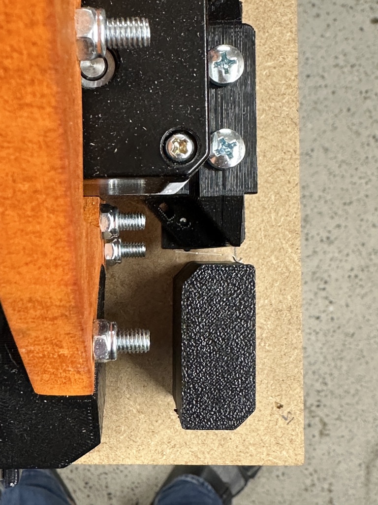
Also, the screws I have do not fit through the keyholes, both from the original generated svg and also the openScad Variant for the nameplate. So to take out the strut plates I have to remove a lot of screws, I would rather avoid to take them out again… They are too wide at their hat. Following makers: be advised to check this beforehand since it will make assembling this much more comfortable ![]() Ryan, maybe if something got mixed up or the generator should maybe be adjusted for tolerances in your supply… I got them with the kit. Can send measurements later, forgot to do it.
Ryan, maybe if something got mixed up or the generator should maybe be adjusted for tolerances in your supply… I got them with the kit. Can send measurements later, forgot to do it.
2 Likes
And I also did the Vroom Noises to not jinx the build, but can‘t upload the video yet. I have to re-activate my Youtube Account for it ![]()
2 Likes
I had this same issue.
1 Like
So were the rails cut too long? or the struts cut too short? If you slid one tube out far enough to get a pipe cutter to fit…, and then slide it back in and the other one out.
Something like this:
EDIT: Well, just now thinking that 1.3mm is too close to the edge for that kind to work right.
…Maybe grinding off the excess with an angle grinder, or cutting off with a dremmel tool loaded with a cut off wheel.
So sorry to hear this. Don’t know of an easy fix.
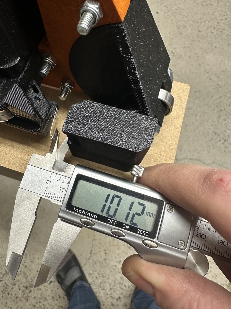
Yeah, the mistake is entirely mine, I cut the rails 1mm each too long ![]()
the struts are to the plusminus 0.1mm 1422mm long as generated by the calculator.
But from what I get from your answer, I will wiggle the pipe out far enough to make another cut - and try to not have to disassemble the whole thing… to try and maybe safe time on fixing this. I will rather stay on the shorter side since undersizing by 0.5-1.00mm seems to not be a problem so much than too long tubes ![]()
Might not work with the wiggle-out since the 9 clamps have a very good amount of lateral grip already without any bolts tightened, but then I will just take it apart, in the end it’s not too much.
I can still rotate the pipes in the clamps if I force them, but they sit absolutely tight and dont move sideways if not rotated at the same time with much force. Sliding them on was a perfect fit - the tolerances seem to be just right with this. ![]() Props for the design of this part, very snug
Props for the design of this part, very snug ![]()
1 Like
OK, let us know how it goes.
If you are referring to the braces on the gantry (beam) that’s all Ryan’s genious!
Yeah I know, that‘s where the praise was directed at. I hope he sometimes looks into these threads and is happy to read about it ![]()
2 Likes
So… I did take out the rails again and cut them again. This time I undersized them .5mm. It all fits perfectly and is very sturdy. Looking forward to making the rest of the assembly this week.
1 Like
Awesome!
Omg how would it cost to ship one to Michigan USA??? I love espresso!!! And have worked as a barista for a short period, (very short lol, i filled in when they needed someone)
Did i say i loved espresso ![]()
1 Like
Love this! I truly love that the internet has no borders!!! Your story here is an awesome read!!!
1 Like
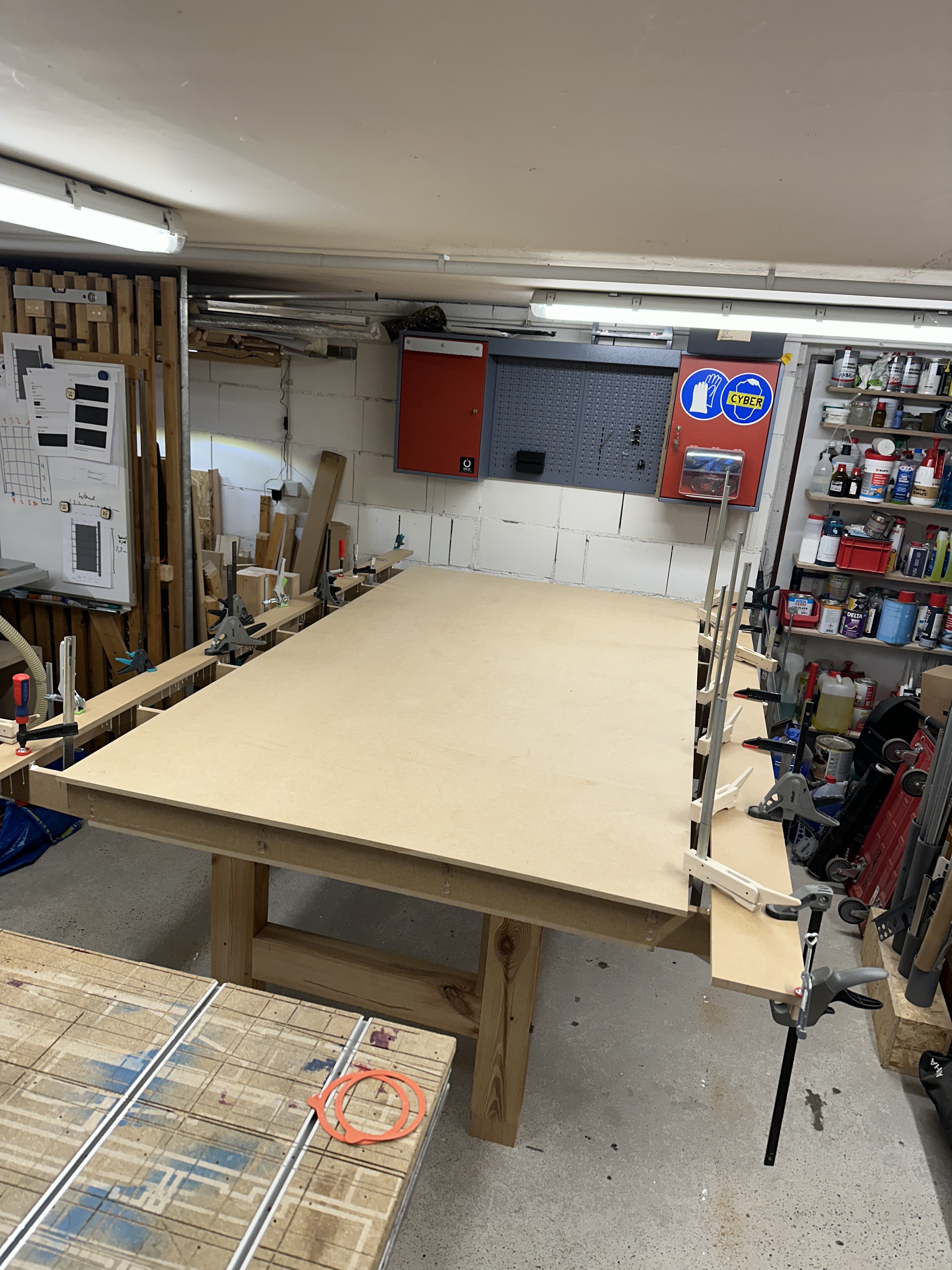
I laid down the marks for the belt holders and the rail blocks and I have a question. For now all things match: the space left and right of the Lowrider on my table, the position of the Y-trucks and the outline for the belt holder etc.
Also the table is square, the toe and heel distance of the Lowrider is the same front and back etc.
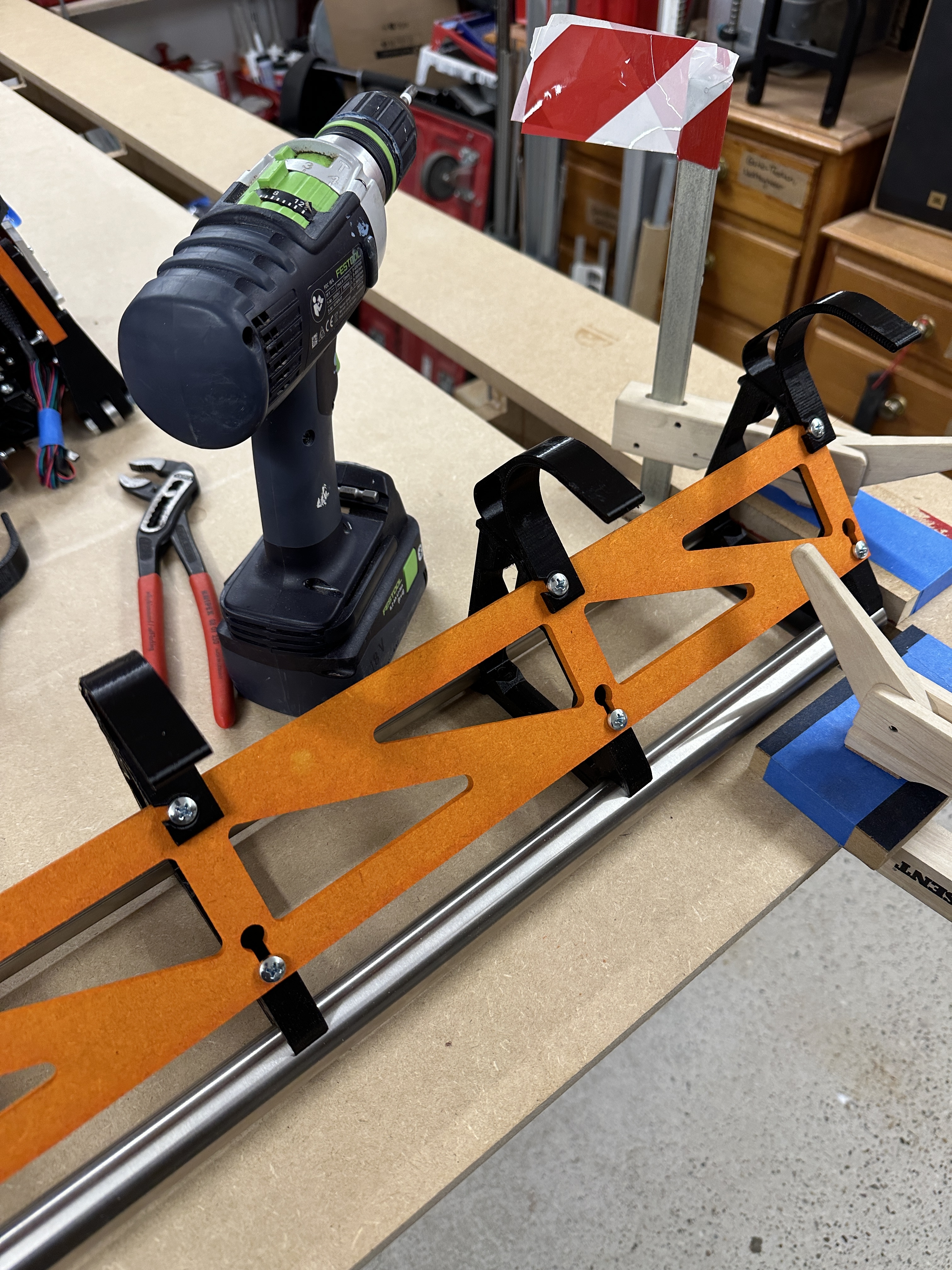
But: When I roll the machine all the way to the front of the table, the right side triggers its endstop about 10mm before the left side does, even though they are placed at the same distance from the end of the riding plate… I can hold the low rider on the right endstop and pull the left side to the endstop to trigger both at the same time… It does not require a huge effort. Is this normal and something that will be handled later on? Or should I correct this better now than later? I could loosen the rail blocks and rotate around their centerblock to maybe skew the difference down a notch? A millimeter at the top and at the bottom over 2,70m might make a huge difference.
Any advice greatly appreciated, I feel uncertain how to judge the situation and whether this is actually “pretty okay” or “very bad” ![]() The rail is a bit skewed and I can rotate it so the skew is minimal in the XY-direction…
The rail is a bit skewed and I can rotate it so the skew is minimal in the XY-direction…
Endstop on the right just triggered:
Endstop on the left still 10mm out.
1 Like
Just finish building it and then home it. Do the squaring procedure, only then you will know whether you built it wrong or it’s just a little twisted. ![]()
Yeah… I will probably… But I had to finish work in the garage anyways today so I thought I’d ask before I return. If there is no conclusive information I will just go ahead and finish the build. Wanted to do some meditative cabling tonight ![]()
I ran into the same issue. Ended up replacing one of the printed parts that meet up with the XZ plate.
I can indeed make it jump of the rail if I pull a bit further. I will check what you did with the gantry and the parts.
I am following along with interest. I cannot tell if you are thinking it is due to the gantry itself having some skew, or all a slight misalignment of the Y rail, but it sounds a little bit like you think it’s the latter. ?
I did after @jeyeager post check my gantry and indeed there was something off - not the whole thing but the lower right corner was not right and somehow deflected the gantry a bit and over the length of it that little flex might induce enough twist to at least explain some of the distance… I did not manage to identify what exactly went wrong but it was not perpendicular and the gantry was slightly twisted/out-of-angle. The result when measuring it looked more or less exactly like
in the thread above but it was on the lower tube.
I did reprint the sidemost brackets just to make sure and re-assembled the gantry. It is now supersquare™ since I checked every step and I reaaaally don‘t want to take it apart again (remember, the bolt heads don‘t fit my T-Slots ![]() ).
).
It now measures exactly 1442mm across all 3 lengths and lays flat as an angle-iron on the bench on all three sides. Hopefully that fixed it.
I will try tonight what changed when I replace it on the rail and if there is not significant improvement have a closer look at the Y Rail as well, which is indeed what I had in mind first but after sleeping over it I decided to have a look at the gantry first because everything about the table is CNC-parts I made and confirmed while making them… and therefore should not be more than 1mm off in any direction or group of assemblies (which it so far is, much to my enjoyment ![]() ). Since I was careful with reference sides and measuring I should have placed the rail mostly within its exact position. This - by the way - is the reason it bugged me so
). Since I was careful with reference sides and measuring I should have placed the rail mostly within its exact position. This - by the way - is the reason it bugged me so
much. Everything I measured was <1mm off, even over the whole table distance and also the diagonals. Seeing the endstop so far off - I felt something must be going wrong somehow ![]()
2 Likes
Wow, OK please keep us posted.
I took some time this morning and looked at the brackets that were installed before I replaced them. There’s nothing wrong with them and it was probably totally unneccessary to re-print them. Most probably something got pinched when assembling the first time. I noticed that when tightening one of the upper screws connecting the plates my tool got wedged between the plates. ![]() But as I said above, I did not find anything conclusive on what went wrong…
But as I said above, I did not find anything conclusive on what went wrong…
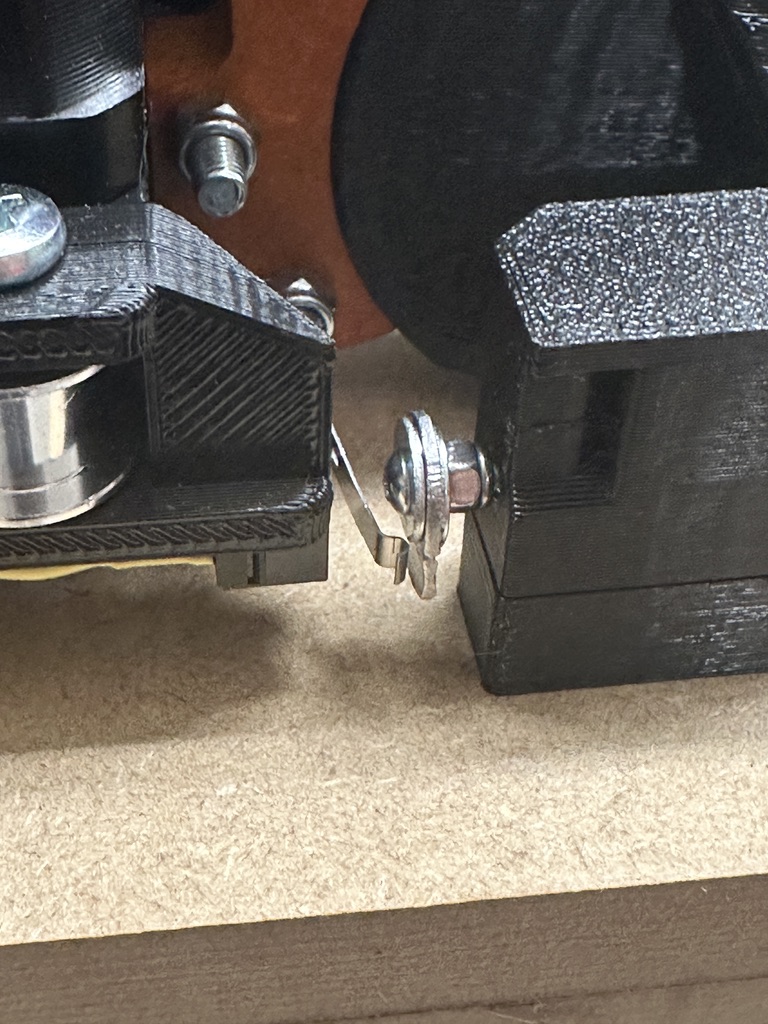
Well… I made a mistake somewhere, but now it’s square and I added a little screw to trigger the endstop and now they trigger almost simultaneously, which should be well manageable within the configuration of the software. I will see where it goes from here, but I am not worried for now.
1 Like