Lol. Ok! I’ll make a few more minor tweaks tomorrow. Then test them. Then post the STLs later this week. By chance do you know what size (length) rails you will want to use? I can pre package some of the DXF files as well.
Oh boy! I just realized I’ll need to make assembly instructions… sigh.
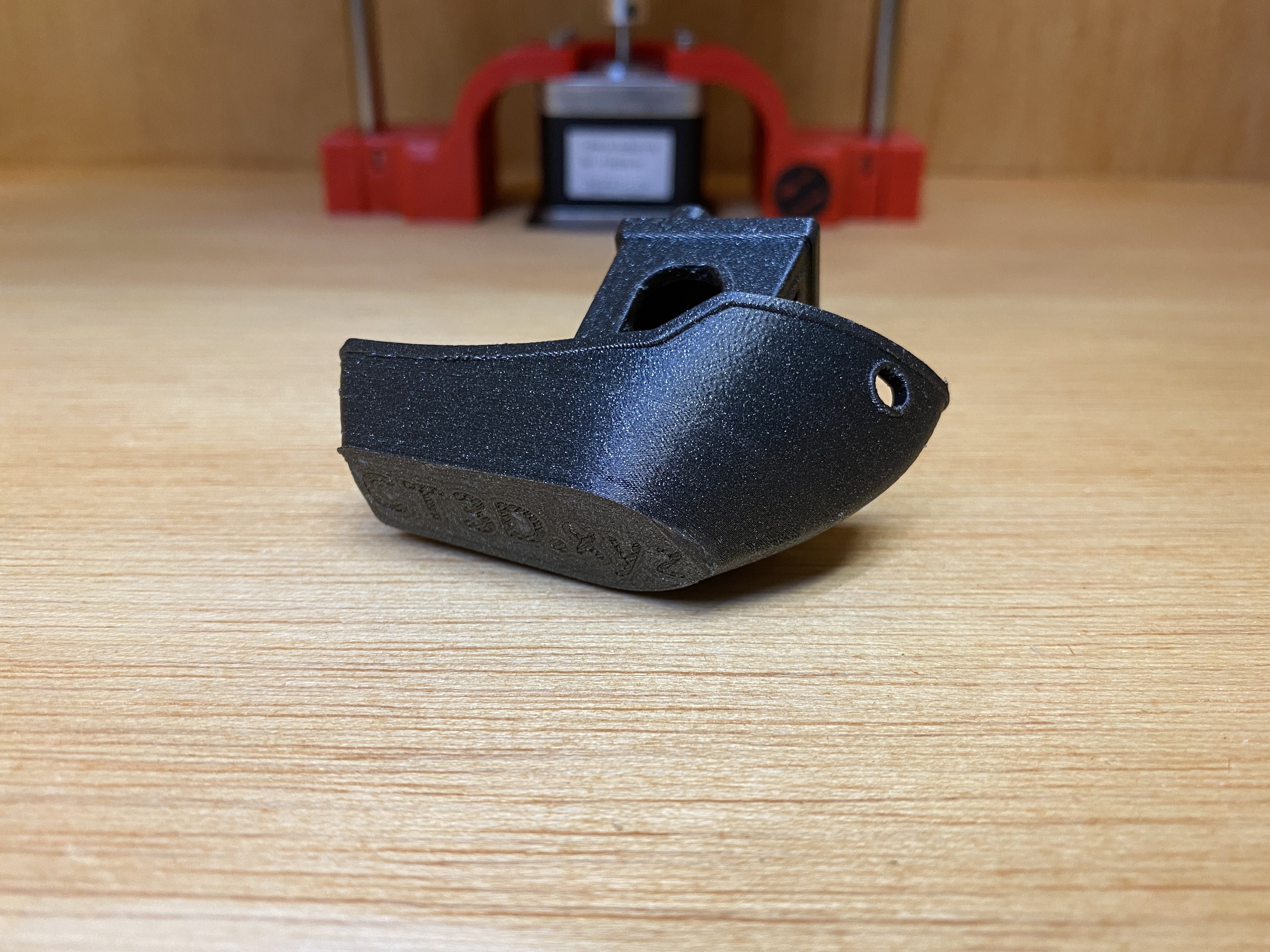
Today I was testing the sock that goes over the 608 bearings. First version works but I want to tweak it a bit. Good news is this one is compatible with the rest of the CoreXY parts.
In the video I can see the belts might be a little tight.
Perfect is the enemy of good. There are a lot of people who could use stls, dxfs and a bom without instructions. Just my $0.02. instructions are tough.
i probably wont build it for another month, i am interested in the box and the printed part STLs but i think i will modify to use tubes for rails, up the size to at least 12"x12"x12" and i might use acrylic rather then wood. haven’t decided yet, a lot will depend on how much funding i have after completing my MPCNC.
and i agree with Heffe, i’m less interested in instructions, maybe a diagram for how the printed parts assemble after all a picture is worth 1000 words. and instructions are a pain.
My printer’s belts are tightened with the help of a sound meter. Most of us tighten them so they strum at about 60hz. A lot of us are seeing a slight 2mm ripple on straight walls. You really need to look to see it, but once you’ve seen it, you see it in a lot of other printer’s prints. One of the guys was testing ways to mitigate the ripple, so he kept tightening his belts. He said at around 120hz they’re almost gone. Turns out it’s the teeth on the belt that causes them.
The frequency should be based on the tension and the length. So a specific frequency for a specific length makes sense, but it will change if you want the same tension on another length.
I am having some funny ripples on my prints (I am printing some one wall boxes). I’ve seen ringing before, but it naturally gets smaller as it moves away from the edge. This is the same size all the way across. I was wondering if maybe it was 2mm, but it is actually 0.7mm peak to peak. That is odd because that is close to sqrt(2)/2). This is a corexy, which uses two motors to make that wall. But I think as each motor moves 2mm the nozzle moves sqrt(4+4) or 2.8mm. not sure how it can have 4 bumps when the motors move one tooth. But I suspect something is funny.
When I take apart my TAZ 5 and rebuild it as a Timber Bot I want to see if I can make it use two print heads. Dual print heads are bulky, heavy and prone to oozing. I thought about building it like an IDEX where the two print heads have their own X belt and stepper but that wouldn’t work with the CoreXY setup I just spent so long building. So my brain moved to a tool changer. That sounds like fun so I want to give it a shot. I remember the one I saw for the MPCNC and thought that was super cool. Anyway… my problem is the rails I already bought are too short. The ones I bought for my TAZ are 350 mm long. The tool carriage uses up about 45 mm of that and the bed is 300x300. So I don’t have any extra room for a tool changer. Or do I?
Well I was thinking about the BB bearing rails @dkj4linux made for his laser engraver linked earlier in this thread. I was wondering if I could use that concept to “Extend” the steel rails. Build it to use the steel rails for the printable area but then make a plastic 3D printable rail that could extend the movement into another area that is only used when the machine is changing tools.
So here is the first proof of concept. It works pretty well. I’ll bet If I post process the print a little with some sanding of the flat top surface and clean up the end It will move even better. I should probably use a PLA + rather than the PETG I tested with.
Just another thought… would it be possible to mill the rail out of aluminum on an mpcnc? Also as an alternative to tool changing (awesome as it is, its a lot of complexity) what about using a series of bowden hot ends? Would be a lot lighter and simpler? Even if your not interested i would love to hear your thoughts on these ideas for when I build a 3dp
Dude, I’ve been looking for a reason to cut something aluminum or steel on my teeny tiny burly. I actually just took it off the “busy” table and set it aside because I haven’t been cutting anything but wood, and I’ve got a big primo.
How would we keep the truck captured? Something like a trapezoid profile, but more narrow on the bottom? Then how to keep the truck from dragging on the mount surface? Two piece? Regular bar stock underneath, bolt through?
I was thinking of copying the same design of the basic sliding rail… the carig rides in the groove on each side right? So we just mill the grooves into the side of the bar stock, mill the screw holes into the top… but I’m new to milling and cnc so there is probably a better way.
It would be super nice to handle it in one setup. Having to reposition the stock with a flip requires a certain account of technical…finesse. I gotta go find what that profile actually looks like, now.
Not really if you start with the screw holes on the top, then use them screw it to a board on its side when you flip it, it should be perfectly (within the tolerance of your cnc) mirrored right?
Theoretically, sure.
In theory, theory and practice are the same. In practice, they are not.
I’m sure we have some folks here who could do it, but I’m equally sure that if I tried, they wouldn’t have the precision we want for a printer.
Turns out there are a bunch of different profiles, so I think we start with the truck and pick one that uses an easy - to - machine rail.
Cool idea with the milled Aluminum. I eventually want to build a dedicated machine for the task. But my current MPCNC is way to big for that now so I won’t be able to help prototype these even though I want to.
As for the profile. The MGN12 rails have a profile that might be difficult to mill. Here is a picture of the profile.
The angled grooves are where the ball bearings make contact. The deeper channel is for the thin metal wire that helps to hold the ball bearings in place. Both of these are slightly exaggerated in this picture because of 3D printed plastic tolerances.
So while I like the MGN 12 rails because they are easy to find and relatively cheap. It may be difficult to mill a matching rail. It would be cool if we could though.
Been there done that. It comes with some cool advantages and two big disadvantages. It works and it is light weight so that’s cool. But Bowden tubes cause more oozing. I don’t like using Bowden setups as much. They suffer from problems that linear advance try’s to solve. But even with linear advance they don’t print as cleanly or as reliably as direct drive. In my experience. With that said. If I can’t get the tool changer to work I will switch to a dual head that has a direct drive and a Bowden.
To recap. I have decided for myself that I would rather have a slower direct drive than a Bowden. But my Prusa mini and Ender 3 both have Bowden and they work pretty well. They string and ooze more than my other printers but still look good.
I have considered for a while trying to design a shaft based remote direct drive extruder, or a solenoid based gear switch so 1 motor can drive 2 (or maybe more) extruders. If i make any progress i will poste it on here… maybe it will be the best of both worlds
I do look forward to seeing what you do with a tool changer though. Having one opens up a bunch of options!