https://www.scrapmetalforum.com/computer-recycling/24770-hard-drive-case-grading.html
1 Like
Not directly linked to the MPCNC/MP3DP printers, but your metal casting got a certain ring when I saw this new youtube post by “The 3D Printing Nerd”
A volume that is filled printed with metal powder (and sand for the supports) and then is “cooked” to fuse the metal, the sand being taken out afterwards. Ah, that would be a new printing head set for the MPCNC for sure :)))
(Arghhh, can’t get the Youtube video link to work ! :((( )
Hey guys, I just watched that King of Random video a few posts up. If you go this route, DO NOT STORE IT OUTSIDE!!! Even when plaster is cured, it will absorb water. Heating up wet plaster is basically setting the timer on a steam bomb. It’s also a really shitty insulator.
The two kinds of fire brick in my forge are lightweight insulating block, and standard fire brick. I got the lightweight stuff off amazon, but the standard bricks locally. These should give you something to go by to find locally if you can.
Yeah, that is the kind of firebrick I’m using for my furnace.
About plaster, it is really important indeed to dry it perfectly prior pouring any hot metal in the mold. Otherwise you might have some pretty dangerous explosions of hot aluminum. My method is to let the plaster cure for a day or two, then put it in the furnace and slowly heat it up until it reaches about 5-600 degreeC. I usually heat it for 12 hours or more, just to make sure it is perfectly dry and that the PLA completely evaporated.
After that, it is pretty safe to use, but I still recommend to pour the metal while the mold is still hot, since it will greatly limit water absorption as well as thermal shock. and if you see the metal starting bubbling, then run as fast and as far as you can.
Also, about the King of random, it seems he is in serious trouble now, seen a few videos mentioning he was charged with pretty serious bomb making accusations. Hope he’ll be ok, I liked some of the stuff he posted on his channel, even if it is less interesting recently.
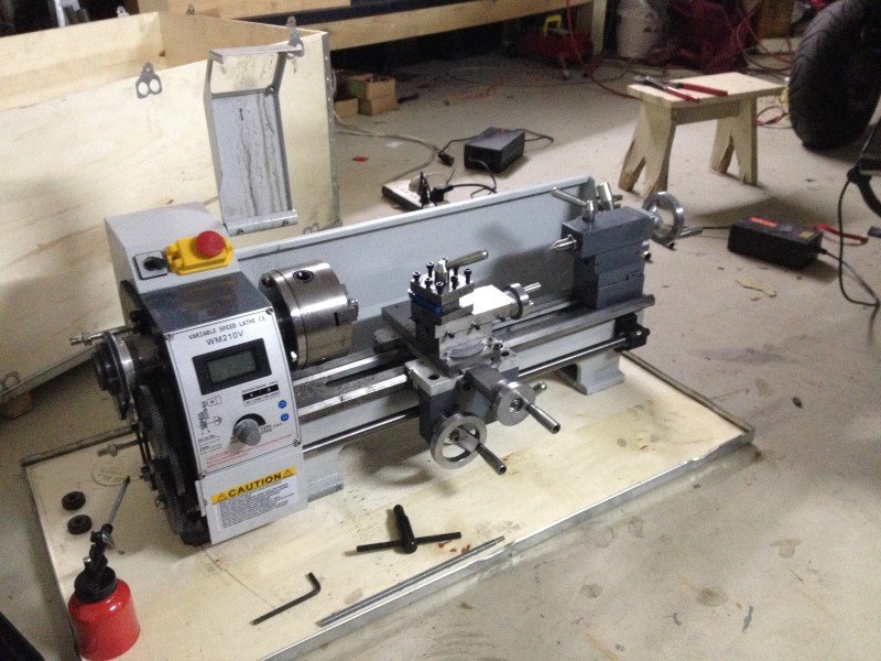
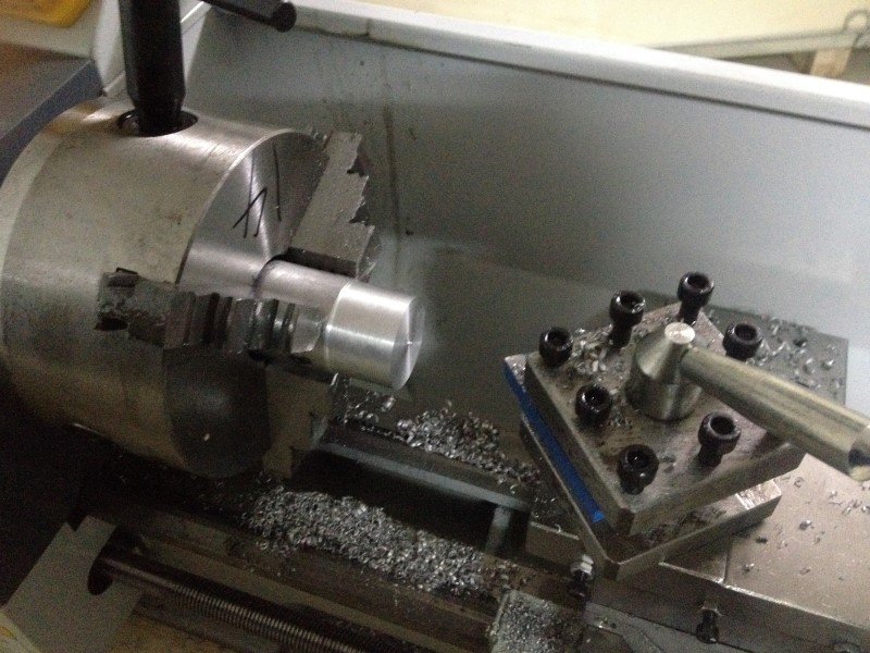
By the way, I’ve just received a new toy for the workshop: it’s a metal mini lathe!
Still need to learn a bit how to use it, but I made a test using the aluminum ingot I’ve made with the old HDD, and it seems to work pretty well!
A few pics, as usual:
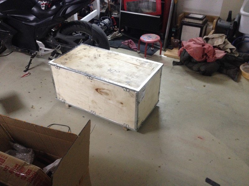
The lathe was protected by a wooden crate. I had a hard time to get it out of it, since the lathe weights about 70 kilos. But I managed somehow to lift it out with my bare hands, though it wasn’t really a piece of cake.
[attachment file=51493]
The lathe ready to work:
[attachment file=51494]
[attachment file=51495]
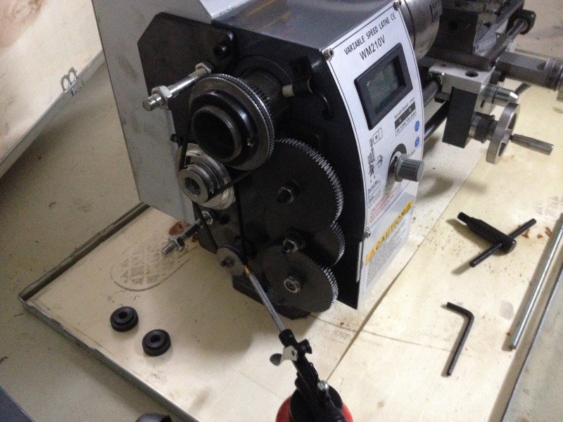
Gearing allows to make threads and power feed for the long axis. Unfortunately there is no power feed for surfacing on the other axis, but I can live with that. Gears are all metal so that’s good for longevity.
[attachment file=51496]
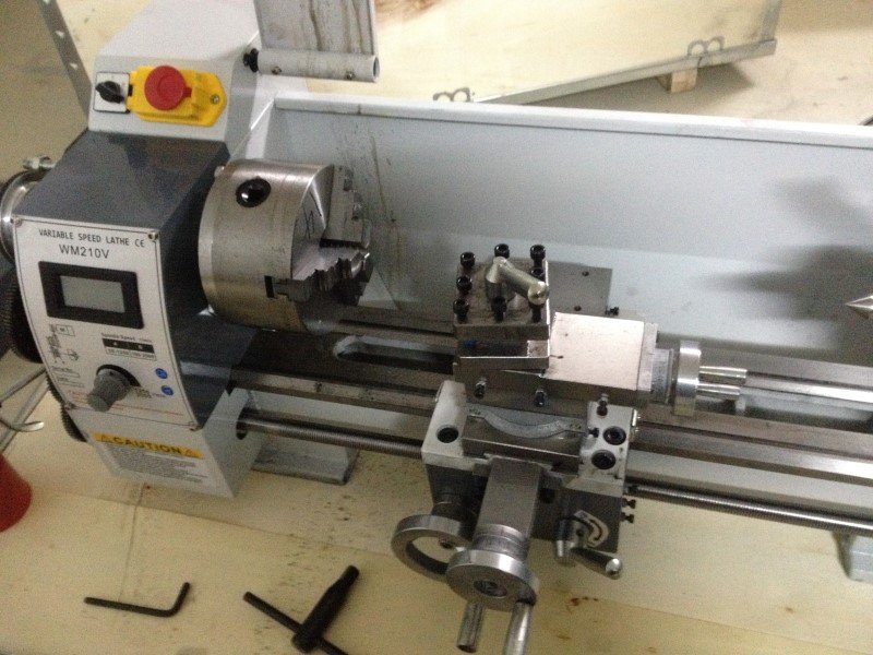
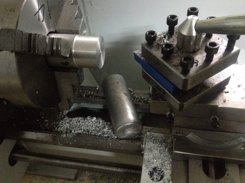
My first attempt at turning the little HDD scrap aluminum ingot. It works pretty well.
[attachment file=51497]
[attachment file=51498]
So far I’m pretty satisfied with this mini lathe, it seems that the quality is decent enough regarding its low price. Now I just need to make a bit of fine tuning and practice!
(and yes, I know, lathes can be dangerous, I’ll be super careful with it) 
2 Likes
I used to have one of those you really need to get the better tool mount. Looks like this, https://www.amazon.com/Jinwen-Tooling-Package-Holders-Multifid/dp/B018QMTXB0 I have no idea if that is the right one but the one it comes with is nothing but a headache.
1 Like
Yeah, already ordered something similar. The original tool mount is indeed a nightmare to set up properly with shims… You can see on the picture that my setup wasn’t right.
From what I’ve red so far, the original tool mount has the only advantage of being extremely rigid, so it is still a good choice whenever you’re parting or doing stuff that needs a lot of tool stiffness.
1 Like
I also ordered that tool mount from Amazon for my mini… I just haven’t actually got it all unboxed and setup yet. I did get the appropriate parts purchased and printed to CNC it and plan on the assembly happening this spring after I can walk more easily. 
hello to all, I am new and I would appreciate if you have the plans in stl of the caruage of linear ball bearings 25mm. thank you very much and excuse my english
Ok, I’m back at tweaking a bit the MPCNC these days.
First project: I’d like to use again the build plate leveling sensor system. Printing works fine now on this machine, but the only real issue comes with the first layer. I generally have to do one or two tries each time to find the correct thickness for this layer, by manual trial and error, which wastes a bit a plastic but also some of my time. Also, the build plate is so big that it cannot realistically be flat enough, from what I estimate there can be as much as one millimeter difference between the highest and the lowest spots, despite having a tile+glass build plate. This is way too much to guarantee a good and consistent first layer. First layer being one of the most important keys to a good print, especially while using big nozzles, I think that any improvements on this side will make a huge difference.
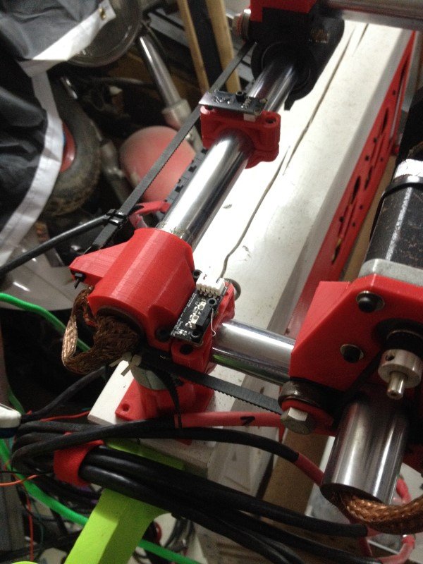
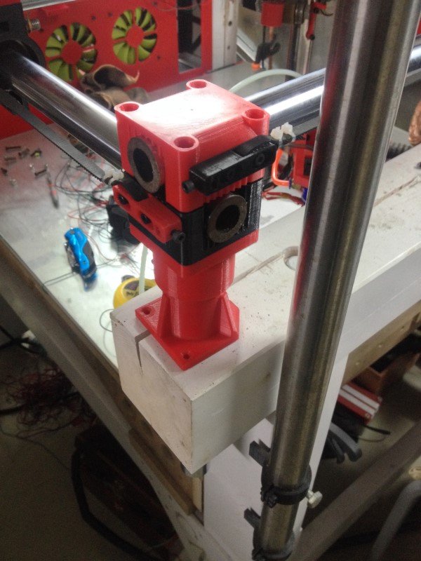
So, I’ve designed some mounting brackets for the X, Y and Z axis.
The X and Y supports, pretty straigtforward:
[attachment file=55821]
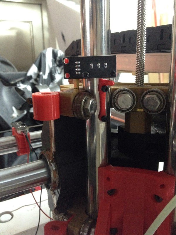
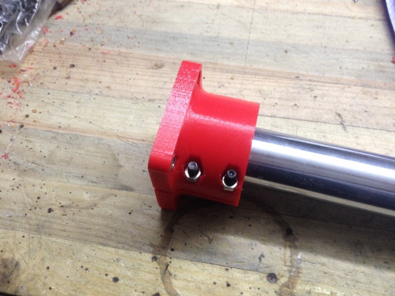
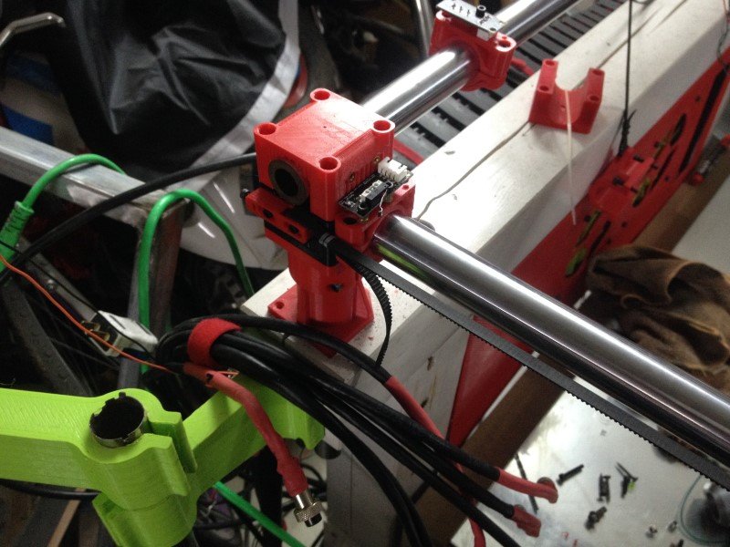
The Z axis top limit switch was a bit trickier, I had to print a little knob thing and attach it directly on the tube.
[attachment file=55822]
[attachment file=55820]
I just need to do the wiring and update Marlin, but this should work just fine.
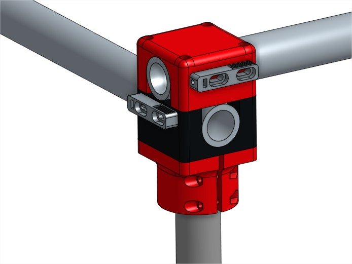
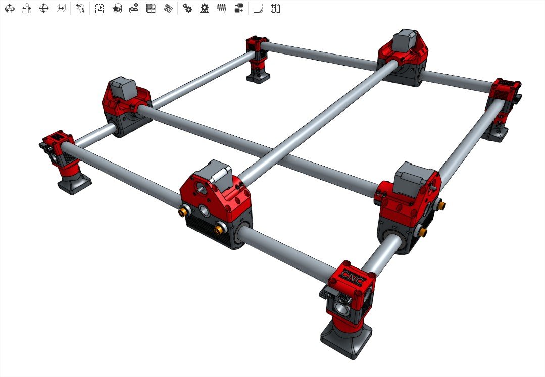
Next project that I already started is to redesign all the corners. Nothing really wrong with the original design I think, but I would like to try and see if another design could help with rigidity. I sometimes can feel the tubes moving slightly while printing or milling, which isn’t particularly good, I want them to be as tight as possible. Pictures will follow whenever I’ll make the first tests so keep following, but this is how they should look like:
[attachment file=“MPCNC corners Assembly 1 - Google Chrome.jpg”]
Probably not as aesthetically pleasant as the original ones, but the long screws and the important volume of plastic on which they will apply pressure on should allow me to torque everything quite a bit before anything breaks.
1 Like
I like the corners. I have a new set of end stop brackets you might like. Not 100% sure how they would work with your limit switches but I’m sure you can edit them. I will try and put them up in a few days.
2 Likes
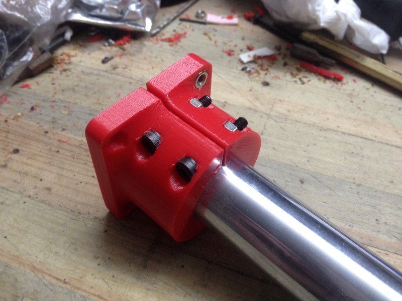
I’ve made a test fit of my first sample of corners yesterday.
It works brilliantly, I’m very happy with that. Well, that was no rocket science so that was kinda expected XD
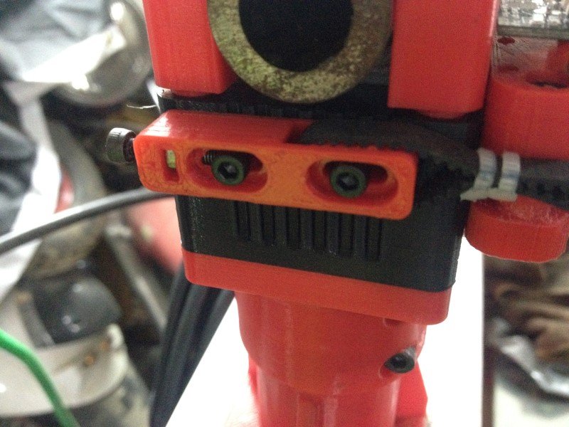
The new tube attachment system: it is super tough, you can really torque up those two screws and it just grips the tube like crazy. I was unable to move the tube no matter what force applied, pretty impressive.
[attachment file=55915]
[attachment file=55916]
Test fit on my machine: I had to redrill a few holes since I made a small mistake during the design, but no big deal. I think it looks a bit bulky and objectively not great, but it doesn’t matter very much to me.
[attachment file=55917]
[attachment file=55918]
Comparison with its father: if it looks bulky, that’s because it is!
[attachment file=55919]
Well I’m super happy with this first design, it feels a lot stronger than the previous corners I had. I cannot move or twist any of the tubes, no matter how much force I applied (and believe me, I tried a lot!). You can put a lot of torque on this setup, I know because I snapped two bolts during tightening tests (4mm diameter bolts, to give you an idea of the kind of force the plastic can bear).
Next step will be to try and make those look a bit better, then print 4 of them. I’ll also probably redesign the foot later, but I don’t really need those on my table actually, they are more decorative than actually useful.
1 Like
Dang you snapped some 4mm screws!! Heck yeah. Gotta see what you have up your sleeve for the belts. I want to switch up my corners a bit to accommodate the dual end stop adjustments a little differently.
1 Like
Well my solution for the belts is pretty simple, just one little part to print, plus 3 screws and one nut. 2 screws to guide the belt tensioner, and one other to adjust the tension. It simply pushes on one of the two guiding screws while being kept in place by the nut. Should probably work fine.
[attachment file=“MPCNC corners Part Studio 1 - Google Chrome.jpg”]
The endstops can be set in place using the unused holes for the belt tensioners, you would just need to add a little bracket. Some would be on top of the tubes, others would be under it.
[attachment file=“MPCNC corners Assembly 2 - Google Chrome.jpg”]

1 Like
Hello guys,
I designed and printed new versions of my corners this weekend… and I’ve decided that, while I’m at it, I should just redo everything, just to see how far I can push the MPCNC design.
I have a few goals in mind:
-Improve the overall rigidity, by linking the tubes more firmly
-Improve the serviceability, by using captive nuts wherever possible.
-Redesign the whole Z axis system to improve its strenght
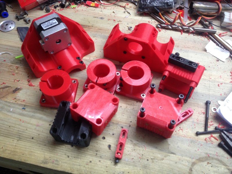
So, first thing: printed some stuff:
[attachment file=56211]
Then test fitted everything on the machine:
[attachment file=56212]
[attachment file=56213]
A close up of the belt tensioning system: I’m super happy with how it turned out, it is quite convenient and now the belts car be tightened enough to act like guitar strings, which could be convenient if you forgot your guitar. I’ll need to experiment to find out what tension would be the best, tighter is not always better.
[attachment file=56214]
And this is how the machine looks like so far. I’ve only done 2 of the 4 corners right now, but the rest should be done tomorrow. I’m pretty happy with how it looks, I think it is not too ugly.
[attachment file=56215]
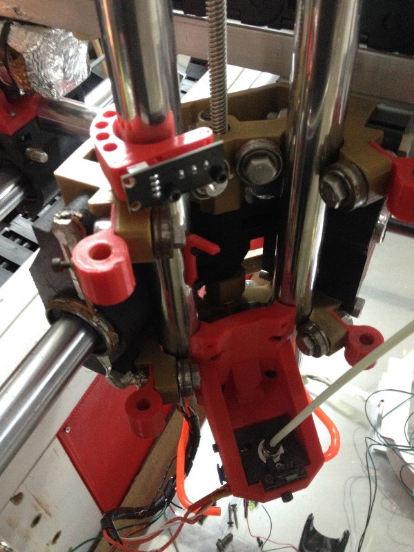
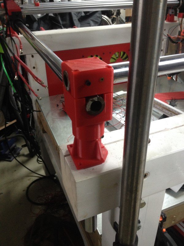
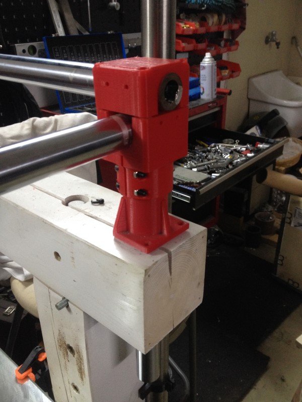
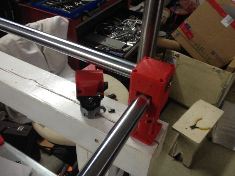
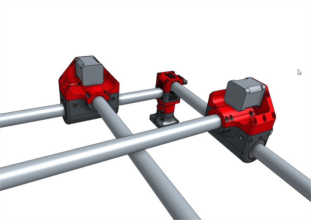
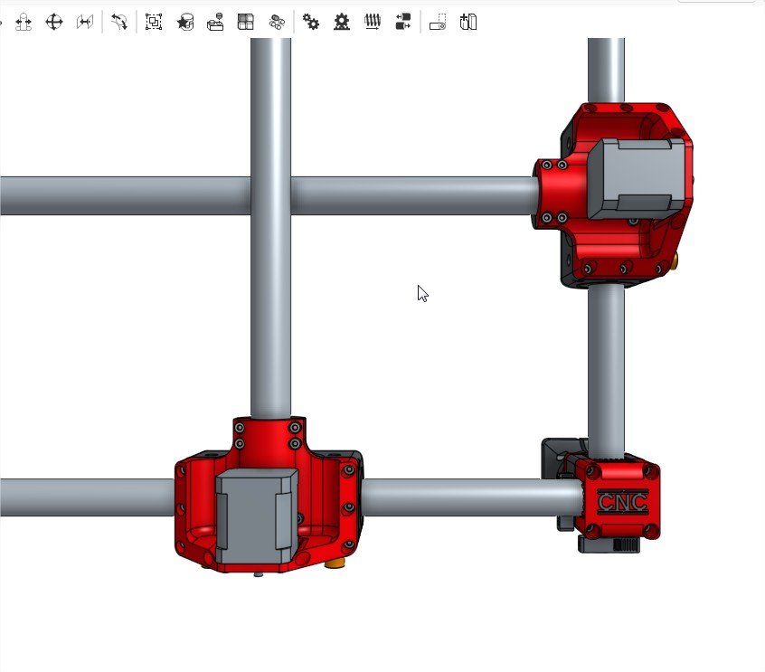
Now, I’m going further with the design process with the motor mounts and rollers. In my opinion, most of the squareness issues might be due to how the motor mounts are attached to the axis tubes. with the original mounts it is a bit tricky to get a sufficient amount of torque to the screws, so in the end the tube is always able to move a few degrees.
So, I’ve designed two new parts, using lots of fasteners to be able to clamp the tube with a lot of force, hopefully reducing dramatically this play. I think it is a bit bigger than it really needs too, so I’m losing a bit of working surface, but I would like to see if a somewhat “overkill” setup would make any real improvement over the original build, so I’ve chosen to push this a bit further than I originally intended.
Anyways, here is how it should look like soon:
[attachment file=“MPCNC corners Assembly 4 - Google Chrome.jpg”]
[attachment file=“MPCNC corners Assembly 4 - Googlessad Chrome.jpg”]
[attachment file=56218]
Now I’ll have to tackle the hard part: the carriage… I’m still not entirely decided yet about how I should do it. I’m still hesitating between building a fixed Z carriage with a moving table, or beefing up the current design by adding one or 2 more tubes… Any suggestion is welcomed, if you have a good idea of design to propose then don’t hesitate, I could give it a try!
See you soon with new updates, hopefully!

3 Likes
I have been trying to redesign without this in mind, seems to be 4 sizes of nuts common around the world. So If anything design for the largest one and make sure a tool can get in there for the smaller ones. You’ll see any of my new parts are only captive on one or two vertex for this reason.
6-7lbs…to much and you can actually damage the belt (tear the fibers and make it far more rubbery) and stall the stepper.
I do my best to leave these loose. The center is the key to the madness, it controls the angle of the rails. Building a crooked gantry and trying to force is square with the rollers will give you bowed tubes. So my view is leave the ends “floating” and get the center built right.
If you are going to make the rollers that large you should make them asymetrical or you are really eating into your build area. Making it stronger just to have to extend the rails (the weak link in the build) is kinda backwards.
Love what you do keep it up. These are just my understandings of the system.
2 Likes
The way I was taught to design is exaggerate the holly hell out of everything and some issue become clear. Here is a thought exercise.
For example a car seat belt.
A wider belt seems like the safest idea, so how about 2 feet wide?
Negatives, comfort, cost, aesthetics, weight of all the jumbo sized components (minor but still a factor in a car), the pillars and attach points would also need to be huge compounding the issue.
Positives, more surface area is safer for our fragile bodies.
This leads to; well all those negatives really call for the smaller the belt the better…Right? Negatives, a piece steel wire would be just as strong but damage the passenger. Positives, all the inverse of the above negatives.
The verdict; at what size do the two balance?
So now think about the MPCNC, make every single part out of Titanium…with 8" carbon fiber tubes skinned in titanium, vs making it with 1/8" wooden dowels.
My suggestion is start fresh. You have never had a barebones stock build in a reasonable size. I think starting there might help you out. Or a new geometry for the size you need, might be a better option? you are kind trying to shoehorn my design to with a extreme Z, which is the exact opposite of the geometry strengths (which are extreme any X and Y lengths).
1 Like
So, I just installed all the new corners, tightened everything and set the belt tension appropriately (yes, I know that too much tension for the belts is definitely not a good thing, my point earlier was just to say that the little system I design was robust enought to handle a lot of force without cracking).
Well, I’m very surprized about the difference it actually makes in terms of strenght. I used to be able to feel the CNC chassis slightly bending and moving while moving the CNC around the workshop. Now it just feels rock solid.
Also, the improvement in rigidity is quite obvious regarding squareness. Now when I move one roller manually, the other roller follows almost instantly. I’ve not taken measurements yet, but I estimate that the play is less than 1 or 2 degree, way less than whatever it was before. I guess the new roller design will help even more with this so I’m pretty impatient to see.
I’ve also re tightened the Z axis quite a bit and not there is no play in it whatsoever. I don’t know why some of the screws were untightened (they were all using locknuts…), but now it is definitely better.
I only get about one millimeter of deflexion while the Z axis is fully deployed using a bit of force to push the nozzle, it feels just way better than before, I had quite a lot of slack.
Anyways, I’ll make a test print this evening to see if this improvement in rigidity actually translates to better printing results, but I’m quite confident.
Why am I not starting fresh?
Because I like the MPCNC design, it works just fine and it is cheap. I just think that a few things might be made better, at least regarding my particular “needs”.
Because I’m not that good at 3D design. Remember I just started learn this thing last year and I’ve only switched from tinkercad to onshape a few months ago. So basically, I still suck.
Because actually trying new stuff might bring more and more knowledge about this particular machine, so it might be useful for the community, at least I hope so.
It has been proven already that the original design works pretty damn amazing. I just try to see if some of the limits can be pushed. The main limit I want to push is printing speed with a big nozzle. CNC works just fine the way it is, I’ve got no complaint about it. But when printing at high speeds, rigidity seems to actually matter quite a bit, because wobbling introduces artifacts and corners are not so great.
Anyway, I’ll print a few parts this evening and we’ll see if this mod actually made any difference.
I do not think anyone in there right mind would agree with this statement. You have a very solid grasp of 3D design.
… Double post, sorry…