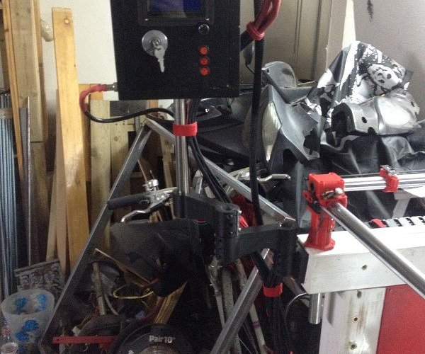
My MPCNC made in China

I understand your point. Making a worlwide doable machine must be a nightmare… I don’t have to consider this issue since I don’t intend to mass produce anything, but I totally get it.

That would be nice if you could come up with a nice solution for that though, since it is sometimes hard to lock things firmly in place on the MPCNC, especially the screws on the corner parts and on the rollers.

Hehe, sure. My point was just to say that the belt tensionners are solid enough, despite their tiny size. I was worried about that before I tested them. Plus I like guitars.

I get your point, but actually, if those are not tightened it introduces a small amount of backlash in all the axis. I’m not worried at all about my tubes since they are extremely rigid (that is, in my opinion, the strong link in my particular machine, because the deflection in those is almost negligible). But I get your idea, and you might have a point. I’ll test and tell you if this actually makes a difference to tighten those hard.

Good point about making them asymmetrical. I’ll keep that in mind for a future version, since I already started printing those things. I won’t extend my machine anyways, I think the build surface will still be large enough, even with a few centimeters lost.

Thanks, I really appreciate your inputs, it helps a lot!
..
2 Likes

So, I’ve made the first tests yesterday evening, here is a little feedback:

Sorry, I forgot to take pics this time, but there were actually nothing really special to see.

I’ve learned something very valuable with these tests: my slicer sucks. I printed 3 things, with various speed settings.

-Thing one: slow speed, slow acceleration,

-Thing 2: constantly increasing speed and acceleration

-Thing 3: full high speed and high acceleration (except for the 3 first layers)

Well, what is particularly interesting is that the results were exactly the same, no matter the speed or acceleration. They weren’t good, but they were surprisingly consistent, with the very same defects at the very same places for the very same reasons. What is very interesting is the speeds that I was able to achieve. 2900 mm/s2 of accelerations on X and Y axis without step loss (step losses started occurring about 3500mm/s2)!

About the speed themselves, I’m not sure since I was adjusting on the fly with the knob, but my standard speed was 60mm/s at 100% speed but I managed to run it a 270% speed without step loss, with contistent and repetable layer quality. That seemed to me almost as fast as the delta, really insane and a bit scary to watch! Super, super fast.

Of course, I plan to be a little more conservative while printing actually useful stuff, but this shows how much rigidity matters when you want to go up in printing speeds. I was totally unable to reach even half of that kind of speeds and accelerations before, the quality would be just too horrible (I tried before, ended up bad).

The overal printing quality was very good for most of the parts, but the little details turn out bad and there is a little of Z wobbling that I can’t really explain (it doesn’t seem to care about speed). The slicer is now the most limiting factor regarding printing quality, so I’ll try to find ways to improve my settings. I also had a few things not running perfectly smooth, but that was to be expected since I’ve just took apart the machine.

I’m not sure my machine actually needs to be more rigid than it is right now for 3D printing, so I’ll first make a few more tests and install the bed leveling sensors.

Good news everyone,

I finally have what I can call a “decent print” out of the MPCNC. Not that the previous ones were absolutely horrible, but in order to be used they needed a lot of reworking, and they didn’t look great.

This time, I think I’ve found the sweet spot. I’ve printed a bracket for the electronic box of the MPCNC and it turned out just amazing… I’ll just let the pictures speak for themselves:

[attachment file=56580]

[attachment file=56581]

[attachment file=56582]

[attachment file=56583]

[attachment file=56584]

[attachment file=56585]

[attachment file=56586]

There is still a few things to be tweaked up:

-The infill and the top/bottom layers, obviously

-The retractions and prime

-Add a part cooling fan

But other than these little issues, I think I finally have a working setup.

Now the next steps is to make it as reliable as possible and to add the bed probe sensor system, because the only real issue with this machine so far is to get the first layer right.

I printed this using relatively conservative settings:

-40mm/s for the external perimeter

-80mm/s for the internal perimeter

-90mm/s for the infill

-120mm/s for travels

The accelerations varies from 300 to 1000 depending of the type of movement. It is nothing close to what this machine can do, I’ll crank up the speeds later. The print time was 1:45. This would have taken 9:20 with the delta. I think it can be done in less than one hour with no major quality issues.

I’ve taken a small video of the machine doing its job, just for you guys:


In the end, the print is perfectly usable right out of the printer, 4-5 time quicker than whatever would be possible with the delta. Huge win!

I’m super happy with this, it is actually better than what I was expecting to get! Keep in mind that this is with this giant 50cm long Z axis!

2 Likes

Good news everyone,

I finally have what I can call a “decent print” out of the MPCNC. Not that the previous ones were absolutely horrible, but in order to be used they needed a lot of reworking, and they didn’t look great.

This time, I think I’ve found the sweet spot. I’ve printed a bracket for the electronic box of the MPCNC and it turned out just amazing… I’ll just let the pictures speak for themselves:

[attachment file=56589]

[attachment file=56590]

[attachment file=56591]

[attachment file=56592]

[attachment file=56593]

[attachment file=56594]

[attachment file=56595]

There is still a few things to be tweaked up:

-The infill and the top/bottom layers, obviously

-The retractions and prime

-Add a part cooling fan

But other than these little issues, I think I finally have a working setup.

Now the next steps is to make it as reliable as possible and to add the bed probe sensor system, because the only real issue with this machine so far is to get the first layer right.

I printed this using relatively conservative settings:

-40mm/s for the external perimeter

-80mm/s for the internal perimeter

-90mm/s for the infill

-120mm/s for travels

The accelerations varies from 300 to 1000 depending of the type of movement. It is nothing close to what this machine can do, I’ll crank up the speeds later. The print time was 1:45. This would have taken 9:20 with the delta. I think it can be done in less than one hour with no major quality issues.

I’ve taken a small video of the machine doing its job, just for you guys:


In the end, the print is perfectly usable right out of the printer, 4-5 time quicker than whatever would be possible with the delta. Huge win!

I’m super happy with this, it is actually better than what I was expecting to get! Keep in mind that this is with this giant 50cm long Z axis!

1 Like

8-O

Impressive work once again Dui :smiley: As someone that produces with their MPCNC on a daily basis, I am always looking to cut part times. I would actually say for whatever reason my MPCNC is not THAT rigid. Unless I flex the gantry with my hands on someone else’s build, I have no comparison. But if I look closely while cutting, I do see that I get some flex here and there. Not enough to cause any serious issues. It is very hard to tell exactly where our flex comes from. In my opinion it is a little bit of everything.

Your prints look fantastic! I am also a fan of bigger prints with a big nozzle. They just come out much more solid. I couldn’t print that fast because the mk8 just couldn’t pump the heat out fast enough. Even at “250c” with PLA, I was getting somewhat cold results.


1 Like

Thanks :slight_smile:

I think you need a better extruder, like the volcano. The reason it works fine is because the hot block is vertical not horizontal, which leaves quite a bit more time for the plastic to melt. You also want the beefiest extruder motor you can afford, with a fair amount of current. I never tried those mk8 style extruder systems, they seems fine but then you have a huge load on the bottom of the axis. I prefer to use a bowden system, this way I can put the extruder motor in a more convenient place.

BTW, am I the only one to not be able to see the smileys on this forum? They are just displayed as an empty square.

It’s a unicode thing. Either your browser isn’t displaying them properly, or Windows isn’t displaying them properly. It’s also kind of a bitch to fix.


What about gif’s?

Yeah, I can see GIFs. Never mind, it’s not really a big problem :slight_smile:


I made a few more tests this weekend.

Turns out that I counldn’t find out the solution to my retract/prime issue on Cura. So I turned out again to the good old Kisslicer… and it turned out to work just fine. So I guess I won’t use Cura again and stick to Kisslicer, except for some very specific printing needs. There are less options in Kisslicer, but the slicing logic is just way better. Cura sometimes feels so stupid in the way it arranges travels, it’s sometimes quite a bit annoying. BTW, if anyone has a really good slicer to recommend, I’ll be willing to give it a try.

So, I’ve printed a little bracket system to hold my electronic box. I think it looks pretty nice, and it is actually quite tough. The parts are perfectly usable and look more and more decent the more I experiment with slicer settings. So far it has been very reliable, I haven’t had a single issue once passed the first layer.

[attachment file=56833]
[attachment file=56834]
[attachment file=56835]
[attachment file=56836]


1 Like

That arm is awesome, I have tons of conduit laying around and that looks like a good use of the small bits. Just like my TV mount, but smaller.

1 Like

Hop, the new corners are finished now:

Just need to print a few more feets and it should be done. Then I can finally tackle the bed autoleveling part.

[attachment file=56944]

[attachment file=56945]

[attachment file=56946]

[attachment file=56947]

1 Like

The new feet I made have 3 screws to let you anchor the far corner to keep it square, then you can clamp the tube and set the other two. They have slotted screw holes as well to let you make adjustments to square and clamping tension. With 4 screws center set you can either tension the clamp or set the screws but not both. If you get a free minute to edit those you might want to get the slots in there it makes a huge difference to squaring, ease of use. I also switched to a thicker wall to increase rigidity and lower the stress on the plastic. I know they look cheesy but they are a big improvement. I am a function over form guy.

Yours do look pretty dang beefy though, I am sure they get the job done.

2 Likes

Yes, you are absolutely right, I thought about this issue during design.

On my particular machine I don’t really need to get these really squared, because the wood chassis is actually doing all the work for me (unfortunately it is not totally square because it was hard to hand drill those holes perfectly square given the tools I have, but that’s an other issue…). IMO, the way to assemble those feet should be to clamp them first to the tube, then adjust squareness and then only screw them to the table once you get the squareness right. I wouldn’t really rely on the corners parts to check squareness since you would have a bit of a hard time to perfectly align them respectively to each other after they’re being clamped anyways.

I was thinking of a different approach originally, which was to not make the corners feet a square, but more like a slight trapezoid. This way, after finding the correct angle through a bit of trial and error, they would have ended up perfectly square after being tightened. But it sounded like a bit of a hassle to design, so I went the easy way. I guess your way is quite easy and convenient too, but I think only one slot is really necessary, the other 3 wouldn’t move much after tightening.

I haven’t seen your new design yet, is there a thread I missed somewhere in the forum? I think I understand what you’re talking about but I’d like to make sure.

Also, regarding strength, I printed those with 4 perimeters and a bit more infill (30% or so)

That is why it took me so dam long to remake such a simple part. I was stuck in that same thinking. With these new feet, you can loosen the screws a bit, like half a turn, and adjust every single one at least 1/8" in all directions. I seriously have never had such a perfectly square build as the last two easily within a half a mm and that is as good as I can measure. Those oversized slots make it ridiculously easy.


https://www.v1engineering.com/new-foot/

1 Like

Hi Guys,

I finally managed to make the bed autoleveling work. Unfortunately, two brave Arduino Mega died in the process, may they rest in peace (I had a short somewhere in the middle of one of my limit switches cable, had a hard time to figure it out).

So it’s been quite a few busy days. I had to print brackets, wire everything, then I tried modifying Marlin to activate the bed autoleveling. I still had the old RC7 version, which didn’t really worked well. So at some point I decided to switch to the RC8 and after a bit of tweaking it finally worked.

So, the one million dollar question: is bed autoleveling actually useful? Simple answer : HELL YEAH!

I’ve used the bilinear autolevel and activated a few extra features to try to make it as precise as possible. Well guys, comparing with and without autolevel is just as easy as comparing day and night. It is just that obvious. I think those pictures speak for themselves:

[attachment file=57198]
[attachment file=57199]

The two parts on the left were the typical results I was having before I had the autolevel. The part on the right was done with the bed autoleveling activated. I should precise that, despite the apparences, the poor results I had were not due to me setting incorrect first layer Z offsets for those prints, it was mostly due to the bed surface not being flat.

Now for a very hard test: print a thin walled stuff accross a very large surface. Basically, if this could pass then I can safely assume that almost anything will pass. So I drew a 50cm square, with a thinckness of 2mm and 1 mm depending on which side, containing a 25cm square and a 10cm circle. Well here is the result:

[attachment file=57200]

Got it perfectly at first try. The first layer was absolutely perfect accross all the bed. Huge, huge win here. The first layer was really by far the biggest issue on my machine.

So now I “just” have to find again the correct settings for the rest of the print (I’ve lost my good configs since I jumped to RC8), and it should be all right. Plan is to get this printer as reliable as my delta. On the Delta I just launch any job with the SD card and move on doing other stuff, I don’t even have to look at the first layer, I just know it will work perfectly. I’ll be happy once I’ll get the MPCNC to work the same.

One question: I’ve downloaded the last version of RC8 on the forum. But I sometimes get the error: “Heating failed printer stopped”. Anyone knows why? My thermistor and heating cartridge are working fine and the temps are extremely stable, so I’m not sure what could cause this.

2 Likes

You should really get into my beta builds and do your settings from there. They have been working on auto leveling for like 6 months and finally seemed to have finished it recently. I have it updated to 2 or 3 days ago.

Well, too bad for me I’m just hearing about that once I’ve finished XD

Do you know how I could be informed of such beta stuff next time?

Is this beta doing anything different from what I’ve achieved ? My autoleveling seems to work pretty well, but I’m willing to change if there is any benefit to do so.

I have the beta linked on the firmware page. The changes happen almost everyday 5 or more at a time. You have to check in on the main marlin branch if you really want to see what is going on. I have started to pay more attention and update when I think something might be good for us. I have not updated the standard builds, I am waiting for 1.1.9/1.2 or Marlin 2 RC to be pegged.

The biggest differences for us have been our dual endstops, better working LCD, accel & jerk. For you the autolevel has been revamped relentlessly for months.

2 Likes

The heater error is because something isn’t warning up as fast as it thinks it should. I remember seeing a comment that it started out too strict. It’s configurable in the configuration.h and since you’ve got a large printer, it’s not surprising it’s taking longer.

While you’re at it, check out babystepping. You can configure it to work with the z offset and it lets you change it in very small increments on the fly. I just adjust it during the skirt if it gets a little off.

Those prints look great though. Good job.

1 Like