My first LR3 build is complete!

It’s been a pretty fun project. I think the most frustrating part was removing the linear rails multiple times because I kept forgetting to install the 3 bolts first, but other than that, it’s really been a pretty straightforward process.

A couple things I’m pointing out here for other newbies to this.

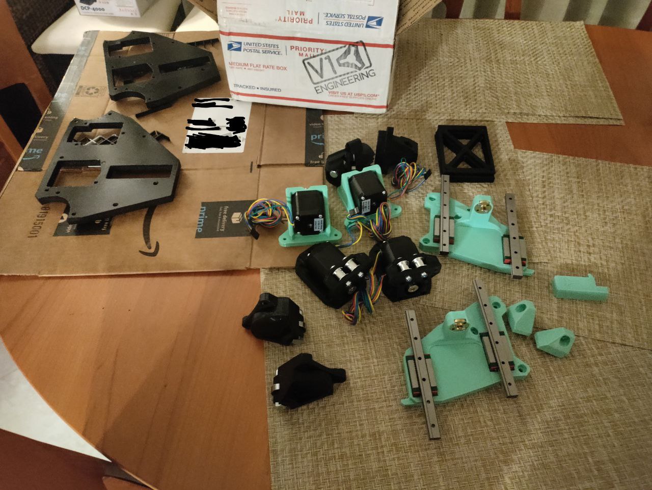
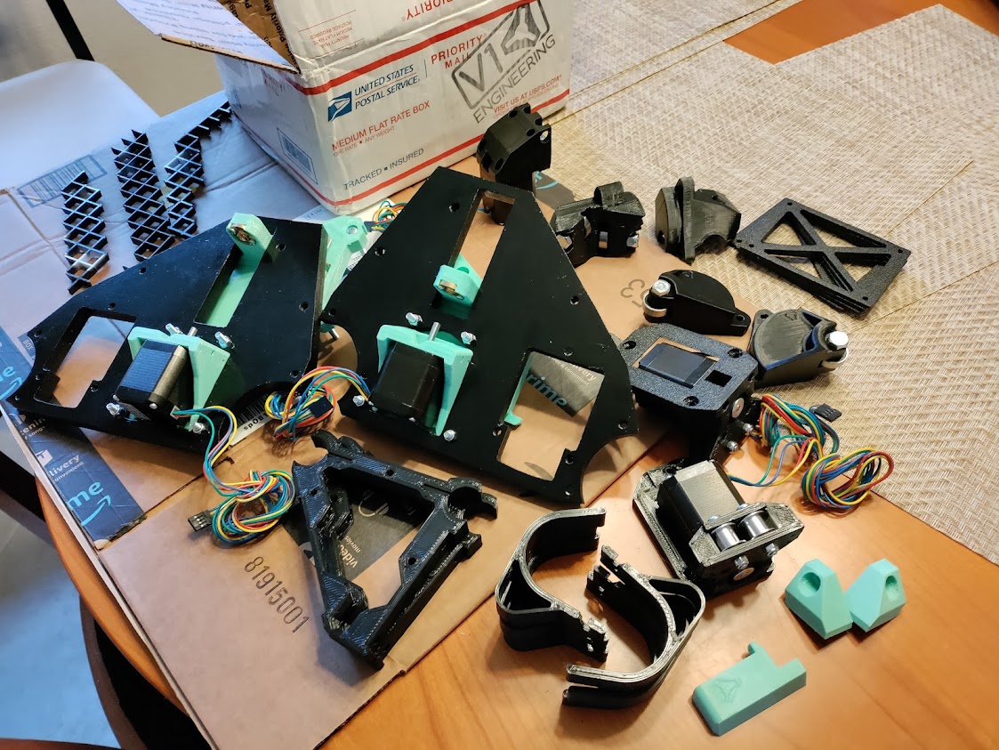
  • It’s worth buying the 3D printed parts if you are in a rush to assemble. I didn’t and wasn’t in a rush, and to me it was awesome to put my Anycubic Vyper to work making something functional. However, I kept feeling like I couldn’t print fast enough. I kept making sub-assemblies at night and would be sad, when I had to stop. really fun project!
    – I used Overture Black PLA for the majority of the parts and Hatchbox Mint PETG to accent a bit
    – I used PrusaSlicer. 0.8mm nozzle. 3 perimeters, 0.28mm layer height, 0.9mm extrusion width, recommended infill for each part. Had really nice detail, but still printed pretty fast overall. With my settings I averaged 70mm/s speed, but typically 40-50% of that for external perimeters.
  • I had to drill out the holes for most of the bolt holes so they would freely slide in. The tolerances for those were a little too tight for me. Best to check your parts before assembling so if you need to bore them out a hair, you can do it in one batch and reduce time and cleanup.
  • Check your XZ plates if printing to make sure they are proper dimensions and the stub is perpendicular to the plate. I originally printed in PETG for the XZ plate. One was a little wonky and the leadscrew didn’t align with the stub nut. Not sure if it just printed skewed, it got dropped, or what, but was not working. The one lead screw was not aligned with the motor coupler. If printing these, stick with PLA per the documented recommended settings. I reprinted and all was good.
  • If you can solder, I recommend soldering your end stop wires to the switches. fast and easy enough and durable. I made sure to cut my end stop wiring to exact lengths. This was necessary for me to eliminate the risk of a taped dupont connectors coming loose. I was shifting some things around before I cut my final struts and while it was still taped, I managed to shake it loose juuust enough that when I went to home Y, I had an open circuit on the one side and had to emergency stop the machine because it was pulling to one side and off of the y rail. My recommendation, solder your endstops, and just cut your wire to the exact or slightly longer length you need to terminate directly to the main board. (I don’t have this issue with my stepper motor wiring. Those I just taped together in the event I need to replace a motor, it’s not too much effort to replace)
  • Definitely Label your wires. Makes reconnecting a breeze. Also take pictures of your wiring so you have a reference
  • wire loom, while unnecessary, really polishes up the build. I used 1/4" braided PET loom for the stepper motors and endstop wiring, and then used 3/8" spiral wrap over 2 1/4" braids on each side. makes the wired stiffer there and looks tough.
  • [EDIT 2022/07/11] a little velcro works great for holding the screen secure to the base but still easy enough to remove
  • Thanks @jamiek for the parametric struts! That tool works great for it! first time I used openSCAD and was super simple to make the adjustments for the width of my gantry and the number of brackets
  • Thanks @jeffeb3 for pointing me to DougJoseph 's updated image for the board wiring
  • And last but not least, thanks @vicious1 for all your hard work putting these designs together and giving me the ability to make!
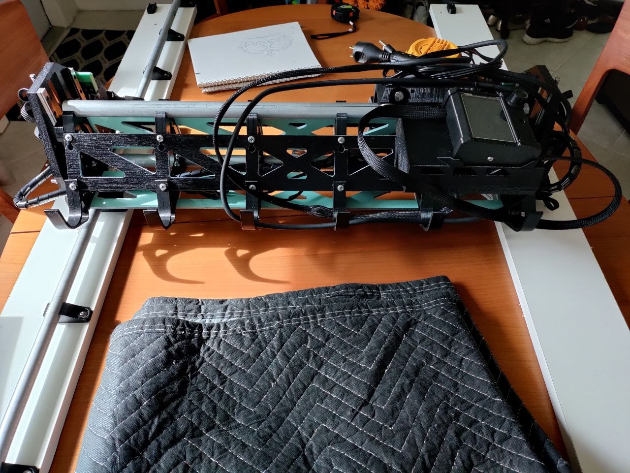
Some Pics


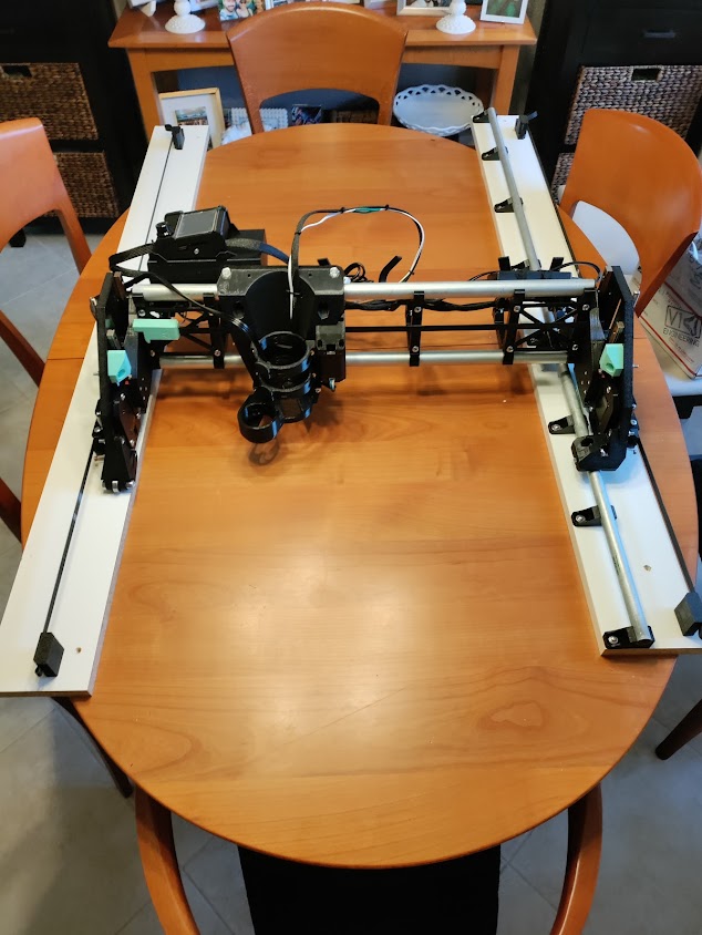
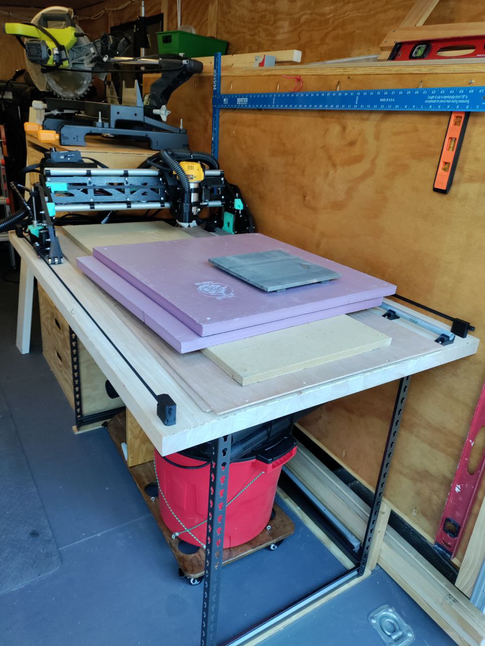
Almost ready to test print, but need to square the frame since it’s too hot to mount to the tablesaw table outside


Test frame attached to do pen crown tests before moving to bench outside


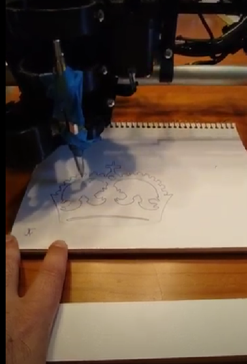
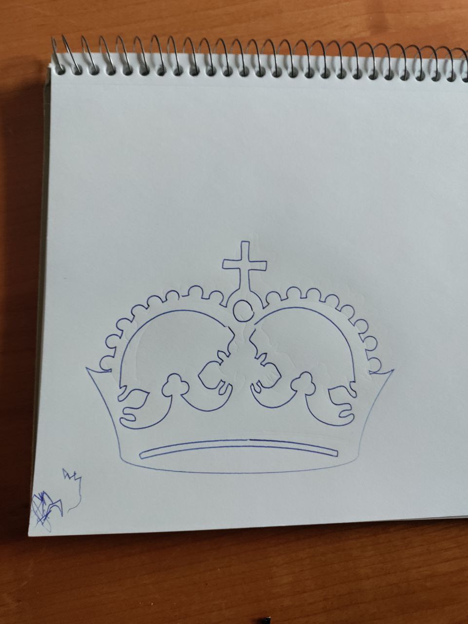
Crown came out good considering my poor attachment of the pen. I did another time with pen zip tied tight in the vacuum area of the mount instead and the crown came out perfect.


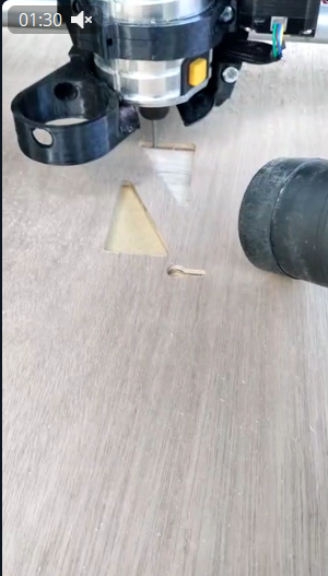
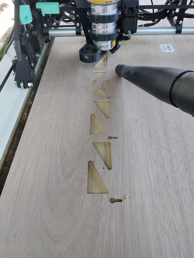
I learned a lot on the first cut. I used 3/16" luan board for the struts since hardboard was out of stock locally. At first I did 3 passes (2mm per pass) and cut too much (total of 6 mm and only 2mm of tabs. just barely over 4 I was already through the board so there were no tabs. I rectified this while it was cutting by popping in a couple finish nails to hold it in place. this was easy since I cut all the interior pockets first and could easily see where I could pop a nail in without it getting in the way of anything. for the 2nd and 3rd, I updated the job to do 2 passes of 2.5mm depth per pass and holding tabs 2.5mm high and that came out perfect. Used all default speeds, cut time for parts 2&3 came out to about 35mins ea. Also check your clearance settings in ESTLCAM. I only had 2mm clearance and my spoil board was a hair prouder on the far Y, so there were 2 little scrape drags at the end of my first cut. I wasn’t going to try and surface my whole spoilboard just for that so I just raised my clearance to 3mm and that was enough to stay clear of the workpiece in the final areas. I’ll make sure to surface my spoilboard flat so it’ll be perfectly parallel to my gantry now that I’m fully built, but for someone new to CNC this is something that i just didn’t quite understand until I started cutting.


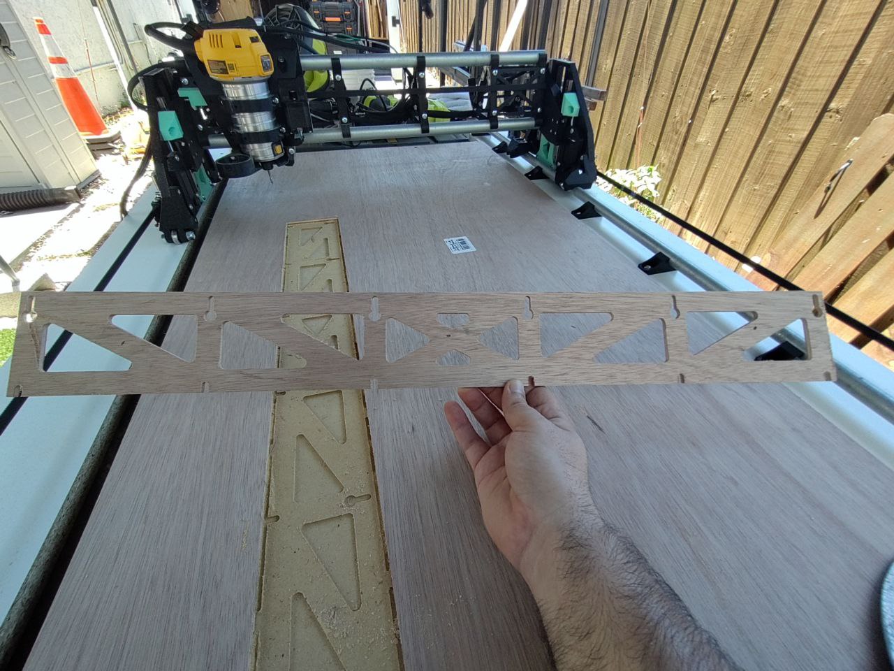
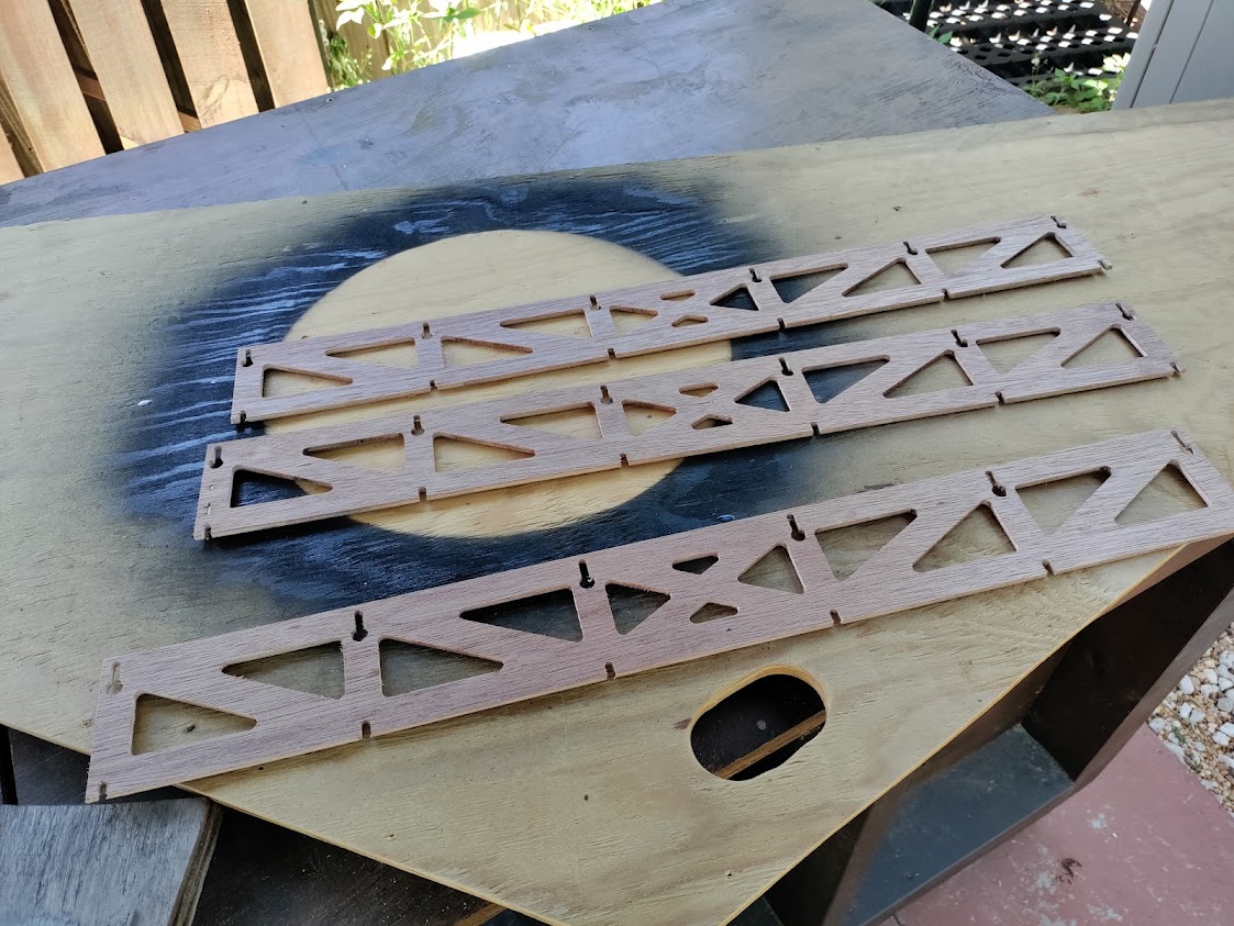
The best part about a CNC… repeatability!


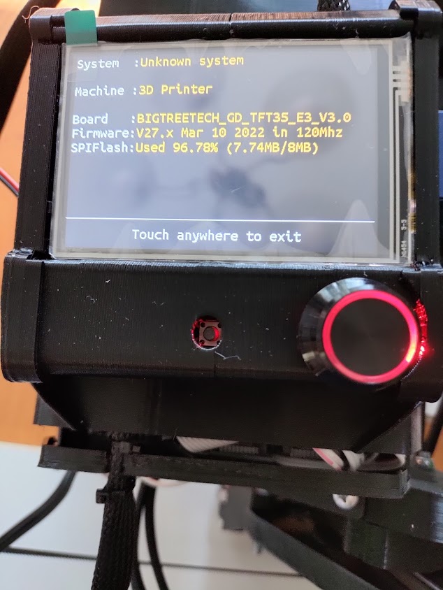
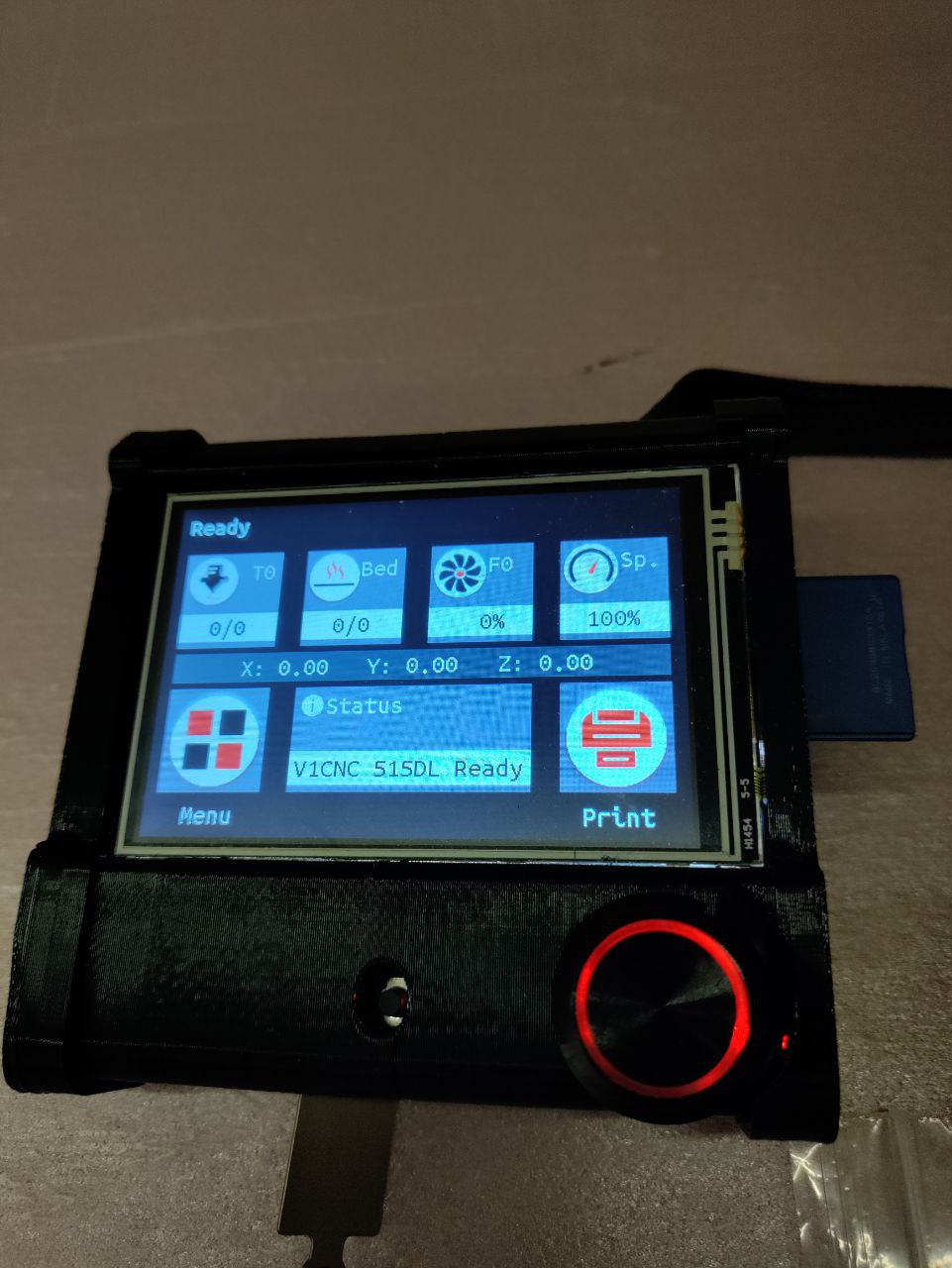
All reassembled, finalized wiring and tested motors and end stop homing. All finished, just waiting on my vacuum tube to come in so I can permanently attach a small tube like in the original photos to quick connect to the shop vac.

12 Likes

Awesome!

Thanks for the tips, I think those could really help some people.

2 Likes

Congratulations @rchamp26! Appreciate hearing about, and learning from your own journey, in this and your other posts/topics. Neat idea to mount Y rail/belts on melamine lengths. Was thinking about using primed finger joint jamb/trim lengths (3/4" x 5-1/2" ?). Cheers!

2 Likes

Thanks! Yeah I have a small work area (8x16 paulk style trailer for my “shop” and most everything i do is under the 10x20’ carport tent where my tablesaw table is). Being able to easily mount and unmount is huge for me. It only take about 10mins to setup and less than 10 to breakdown. best of all i was able to use scrap i had from a previous project of custom soft close under cabinet drawers for my parents kitchen. What i will probably do to give me a nice square lineup is put a fatter melamine board in the front by the y home so i can easily align my spoilboard and stock for cuts when necessary. When i get around to it, will put in some nicer threaded inserts so the screw holes don’t wear out and knock things out of square, but i’ve got some time before that is a risk.

and yeah i cut my board to 5" wide. the y rail side needs that but the other side can be slightly thinner

3 Likes

Thanks for the post. Great work! Like the idea for the Y Rails. I am about to build my table, and was wondering if the spoil board was separate to where the Y Rails are connected, as they seem to be one and the same on other builds I have seen.

3 Likes

In similar situation, looking for whatever’s fastest to assemble, and disassemble for storing. Here’s another example of rails separate from spoilboard @ Cost and Weight smart table designs that would make MacGyver proud - #2 by Dna

1 Like

I would like a “set and forget” way of clamping/securing the melamine rail plates to the table but haven’t thought of anything more elegant than my current way (measured exactly where to place them on my table, clamped and drilled the holes through the board into the table and drove screws in. now i just preset my screws to protrude the rail plate a hair and align with holes in table and screw). It works well and doesn’t take much time, but would like something easier and less to think about being aligned right.

I was thinking of doing something like using a t-track in the table and some type of bolt with big nut, but just seems to use added cost and complexity. and potential interference with the belts/machine unless you waste space in Y to add room for it.

Now that i think about it more, one way that might be great longer term is to just make some 3/4" bench dog holes in the table and make some pegs in the bottom of the yrail plates that it just snugly fits into. :thinking:

I’m really digging the melamine. It was super cheap considering material costs right now ( a 49"x97"x3/4" sheet at the big box here for $39.00), allows for the wheels to glide super smooth, is dimensionally accurate (as long as proper care is taken moisture wise), and doesn’t have any cups/dips in it. If and when it gets damaged from me banging it around moving it, I can easily cut new ones cheaply enough. Too bad I can’t get premade sheets in other colors nearby.

1 Like

I just realized I didn’t answer regarding spoilboard. It was completely separately attached to the table. Just screwed into the table since it’s a “shop” table, but you could be fancy by drilling holes and putting in Threaded inserts to mount the spoilboard.

I’ll probably eventually build out the table more with t track and strips of mdf like most folk do. Seems to be the most practical long term if used a lot

2 Likes

Great job! Looking sharp!!

1 Like

I finally took the plunge this past weekend and built a new table to move my LR3 into my shop trailer so I can work on things if the weather isn’t cooperating. Used the top half of one of those project source steel utility racks (48"w x 24"d) and then cut a piece of butcher block top down to 54"w x 33" D (was the cheapest flattest thing I could get that didn’t require a ton of building aka modified door or diy torsion box (have limited stamina due to some health issues currently).

Using 2 pieces of the 3/8" mdf shelves the rack comes comes with on the top shelf and then routed grooves into the underside of the butcher block in the shape of the “L” legs so the block sits flat on the entire shelf so should have no bowing as its fully supported by the metal rack shelf braces. pretty sturdy so far and no wobble. time will tell if i need to reinforce/brace the legs more.

Cut some small plywood shims to raise the whole table 3/8" so I could roll my existing shop vac /dust cyclone under.

I updated the firmware to the current latest versions ( V1CNC_SkrTurbo_DualLR_2209-2.1.1.zip.

Updated the TFT as well.

I programmed and popped in an ESP01S and was able to get that up and running in 10 minutes and the unit connects to wifi and announces itself is online to me via telegram integration. Sweet! basic movement controls work fine through the web interface as does homing commands.

I used the web terminal to test the zprobe and sending the
G38.2 Z0 ; Probe down to touchplate
moved the Z down and when i touch the clip and the touchplate together the Z movement stops.

I tried loading a the start Gcode onto the SD card and then tried the same sequence and thats where things went weird.

I loaded the start Gcode below into a text file called “probe-test.gcode”
plugged in the SD into the TFT, booted up the machine and went to home each Axis, one at a time.

when each axis touched it’s endstop, it stopped as expected, but then on the screen, i got a Error M420 code.

Seemed weird, but everything else seemed to work. so i ran the probe-test.gcode, the machine initially pauses, then i attach the probe, tap ok and then resume. the lr3 moves down z touches the probe, then drives straight down to the center of the earth. First time i couldn’t kill power quick enough and it snapped the 2 router holder brackets. DOH! printing replacements now.

Below is the code

G92 X0 Y0 ; Set Current position to 0 on the X and Y axes.
M0 Attach probe ; Pause to connect touchplate
G38.2 Z0 ; Probe down to touchplate
G1 Z20 F500 ; Lift off touchplate
G38.2 F20 Z0 ; Probe down to touchplate
G92 Z0.5 ; Set new Z position to thickness of touchplate
G1 Z20 F500 ; Lift off touchplate
M0 Remove probe ; Pause and wait for touchplate removal
;M106 ; This will turn on an IOT relay to start a router or vacuum

While i’m waiting for new router mount brackets, I booted up the machine logged back into the web interface instead and homed the Axis one by one, and I dont see any error in the web ui and nothing shows on the screen.

I tried just issueing the probe line G38.2 Z0 ; Probe down to touchplate and the Z moves down until i touch the clip and plate together and the Z stops as expected.

Anyone have any ideas what the issue is? Can the screen not be used if the web UI is being used/connected?

Seems like something is wrong with the screen.

Do i just need to mount a tablet as my CNC control and abandon the tft?

not sure what i should test next

4 Likes

The code on the milling basics page is exactly how I use it. I see you have added a few things and you are probing twice for some reason?

You do not need these two lines, and the problem could be that you have an F command before the Z command? Not sure but I always put the F command last in the string.

1 Like

I added the lift and second slower probe in hopes it gets a more accurate z before saving and doing the 0.5 mm offset.

Ill play around with that and see if that’s my issue.

Thx for the catch

Separate note, does the M106 command turn on fan0? I haven’t tested that yet. Waiting for the relay to come in. I have the trigger wire for the relay currently wired up to fan0 on the skr pro

The second just cancels out the first. If you want to try and get something more accurate you can slow down the Z probe speed but I think I get about 0.05 accuracy as is.

Are you seeing an issue or just trying something new?

1 Like

Was just trying something new. was thinking of how the zmax homing works and was trying to implement the same kind of thing for the zmin

I rebooted a few times and tried playing around with the probe macro in the web UI and that seems to work just fine.

Also entered the start GCODE there (yours from the milling basics page) as a macro and it seems to work just fine, so will just wait for these new mounts to finish printing in a few minutes and give it a rip

new start gcode works just fine now. thanks for that.

I noticed an issue with the esp3d that I can only see the flash or the mainboard SD card (which on the onboard micro sd it seems to truncate the filename both on the tft and in esp3d)

It can’t seem to read the TFT USB or TFT SD card, (though the TFT SD is visible and functional through the tft screen. I could not get the USB to read in any instance. Tried formatting USB in 4096 and 8192 and neither seemed to work.

It is possible to read from TFT SD or USB and upload over the web to the storage? I didn’t notice anything in the docs or forums when doing some quick searches. I am on 5.15 firmware version

No spaces are allowed. I do think it can see the SD on the screen but I am not sure. The board card slot is best.

I have not tried a USB drive, They are finicky about what they will read, the older the better. New high speed large format sticks will not work.

No.

Yes but it is ultra slow, as in hours not minutes.

2 Likes

Sharp looking build!

:+1:

1 Like