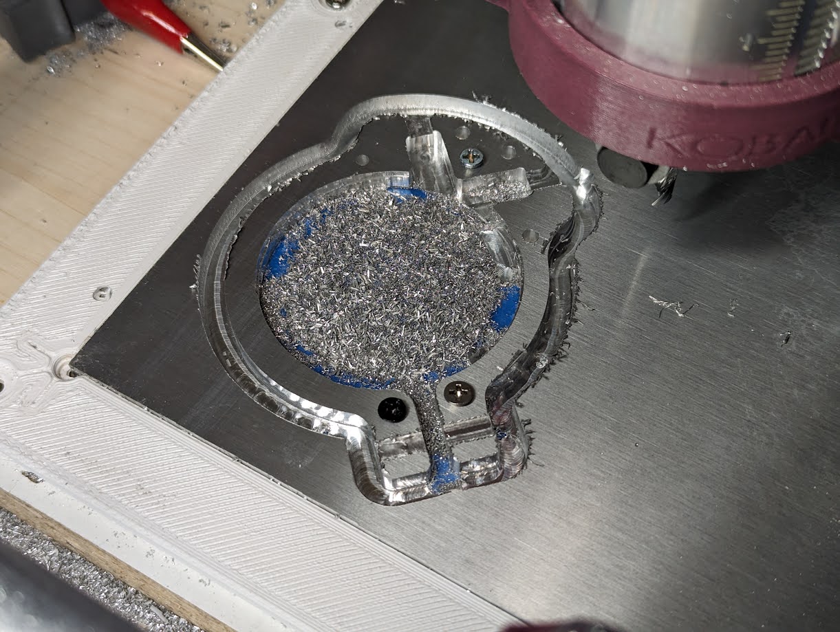
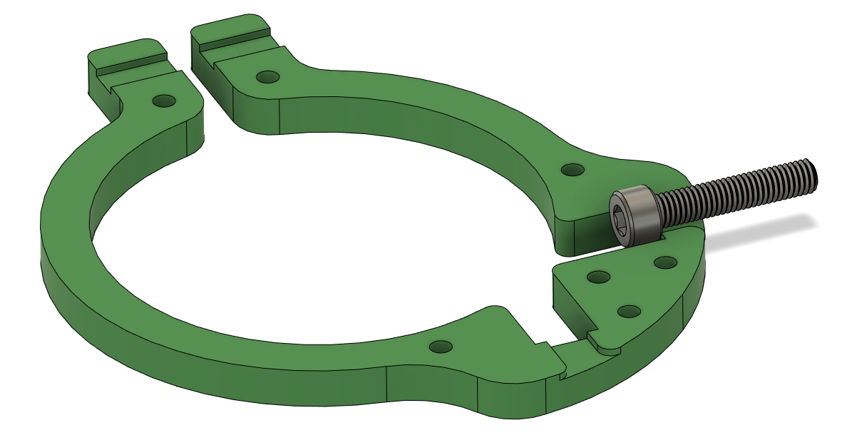
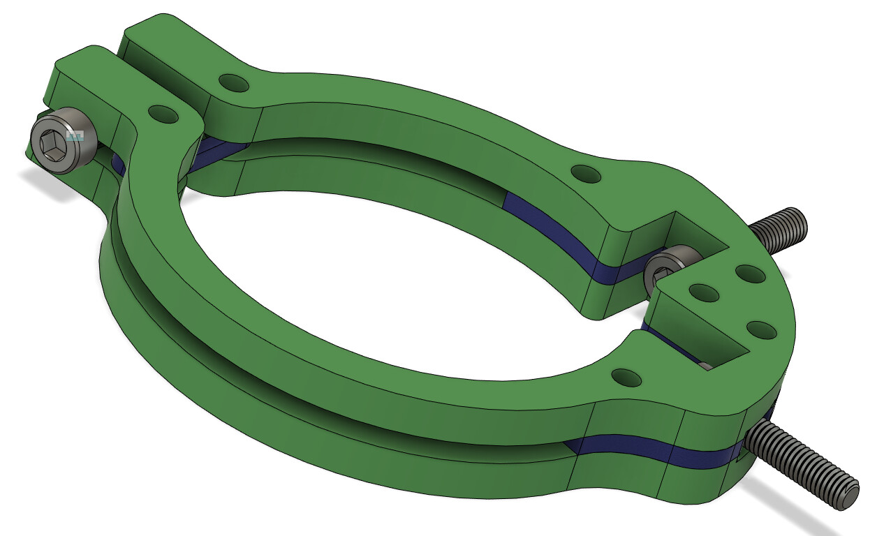
I decided to challenge myself to make an spindle mount clamp out of only 6mm aluminum. This was a funky idea and thought it would be fun to try it out. The finished part is so good it’s demonstrating to me that I don’t actually need an aluminum spindle mount (I currently have the spindle mount printed in carbon fiber PETG)! FYI this is only half, I need to cut a second, mirrored copy that will be sandwiched together.
I had quite a bit of trouble, but most of it was CAM issues. At first I entered some mm/min values as IPM, and had it ramping/plunging at max speed. Also, had an issue with cutting all the way through, and not sure if I messed something up in CAM, measured wrong or if Z was deflecting somehow (ran some of the cuts multiple times by finding the top of the material and G92’ing a slightly higher Z value, so it would dig further to get to Z=0). After a few attempts, I gave up and decided that filing the remaining would be faster.
If I have time this week I’ll cut the other half and try it out. This is only the top spindle mount clamp. I’m fairly certain that will be enough (the bottom clamp would be quite a bit more complicated and seemingly unnecessary, even though it will look weird).
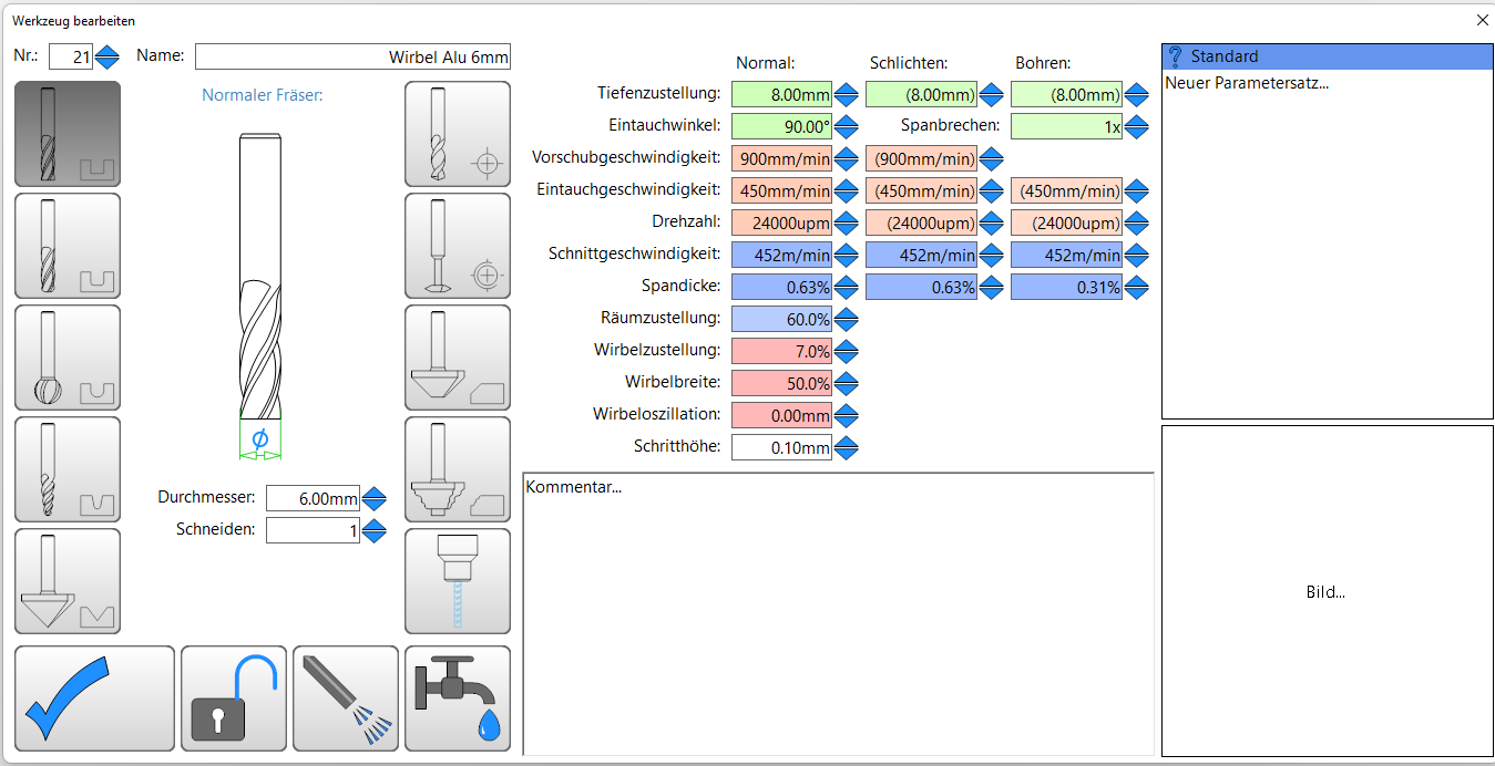
Feeds and speeds, basically straight from this wonderful video:
I also did 1/8" carbide single flute endmill, and everything was the same above except I used 26k RPM, and 2mm DOC for adaptive clearing. Yes, this is not ideal chip load, but it worked. The machine didn’t even make any terrible noises… most of the time.
I don’t have a mist system setup yet. I just had some isopropyl in a squirt bottle and drenched the tool a couple times a minute. I have no idea how much it helped, but the finish is pretty clean and I didn’t break any bits!
Looks really great, the first aluminium part is something special!
You can do it more quickly, while having a longer tool life (you are now only using the top 0.6mm of your endmill) when using my all-time favourite trochoidal milling though.
Here is a shameless self promotion with 10mm (!) DOC and 900mm/mom. There is a bit of flex, it was a stress test, but the parts came out great (the real cutting starts in the second half):
Now chant with me: Trochoidal, trochoidal, trochoidal…
A clarification: I am doing two types of cuts here: contouring where the bit is fully engulfed in the part, and adaptive clearing, where every cut is only on one edge of the bit at a defined stepover.
I use Fusion360 CAM which uses “ADAPTIVE CLEARING” which is a kind of superset of “trochoidal”. It will carve out entire 3D geometries within a given machining boundary, guaranteeing the “optimal load” the whole time (which is basically the trochoidal stepover). Where I used it, I used 5% of bit diameter for stepover/load and 3mm DOC. I suspect I could double both of those but I was keeping it conservative to start.
For contour operations, trochoidal/adaptive is so extraordinarily slow, I decided to trade bits for time. Literally 5min vs 50min to do a single contour operation, even though I am aware that the bottom 0.6mm of that bit is getting all the wear. Honestly, contouring wasn’t as bad as I expected. No terrible noises that made me think the machine was tearing itself apart (or skipping steps).
I think the best option is to flesh out the stock roughly to the size of the contour with a bandsaw, and then use adaptative clearing to remove those extra 3-4mm all around, with a lead-in outside the stock
Yes! Great idea. Except I don’t have a bandsaw… and I’ve never cut aluminum with a jigsaw though I can always try. I’ll see if I can work that into my workflow (besides the inside contour that I cut here, which still seemed like a better option than clear/cutting the entire interior)
First, Hello everyone. This is my first post after reading a bunch of threads.
Now to the good stuff:
I am not new to 3d printing and have … we’ll call it “minimal” experience with CNC mills. I have been looking into both the MPCNC and LR3. I’m torn because I cant see me using the increase in size often, but hating myself for not going big that first I need the extra size. I had thought to myself that if I made an MPCNC I could use that to make aluminum parts for a LR3 (or seems like LR4 might be coming soon). Then I started thinking that I could also make MPCNC parts to add rigidity. Mind you all of these thoughts were just my brain running down rabbit holes without the actual knowledge base to really think it through.
Then I found another thread basically asking if anyone had done the exact same thing my silly brain was thinking up, and that linked me here. I love the “why not try it and see what happens” kind of philosophy. Though I admit you have made my decision harder as I REALLY doubt my desire to purchase a 4’x8’ sheet of aluminum, never mind try to mill it into anything.
I have so many questions, but I am just going to say thank you for the post and the thoughts that came with it for now and keep reading other posts on here to see if my answers are already there for the finding.
I think most people building 4’ x 8’ and larger machines are not usually planning aluminum projects that big. They tend to be focused on projects from sheet goods like plywood, MDF, acrylic, HDPE, foam or maybe surfacing rough wood slabs or lumber.
The LR3 can do a good job of milling aluminum. I try to set up my aluminum stock as close to either end of the gantry as possible to avoid the highest flex at the center of a long gantry.
Welcome! I came to post the same kind of reply as @tgm022861, but he beat me to it.
I would add that this is a bit similar to choosing size on a 3D printer, in that (for many makers) somewhere between 90% to 95% of print jobs can be done on a “normal” small printer, yet for those pesky 5% to 10% of larger items, it can be really nice to have a big printer. It’s much like that with a LowRider.
I would encourage you to go with LowRider versus MPCNC, but it’s very much a personal choice.
I went big with my LowRider v3, and I have made more use of the full sheet capability than perhaps many makers. I make large hexagonal game boards that sell on my Etsy shop, and by having a full sheet capable CNC, I can design the hexagons to be interlocking with each other (8 per full sheet), and thus can rather easily make boards that are literally larger than could be reasonably doable with any straight-cutting device like a table saw, and while it could also be doable with a handheld jig saw, that would be a real pain. I can also batch out the engraving, pocketing, and divots (etc) on the same gameboards, in batches of 8 per full sheet, thus making production easier and quicker than if I did not have a full size capable CNC.
As Tom already mentioned, going big for wood and plastic does not necessitate going big on aluminum, and it can really handle metal cutting, which would likely be on much smaller stock.
@DougJoseph thank you so much for that. I actually first came to this forum to find open discussion between the different models and have yet to find it. So I have been digging through the various ups and downs of each independently.
As for larger printer, I know EXACTLY what you mean. I have 3 or 4 files I have designed to print out but lack anything that can print the almost 24" I need. So now I have to figure out the best way to section those design out without sacrificing any of the function of the parts.
The other comparison in my head is the guy who buys a 2 car garage and then wants to park his dually in it. He would have had a much easier time with a Tacoma. If you haul huge things all the time then the dually makes sense, but if your only hauling your wife’s purse to the grocery store, get something smaller and save yourself the hassle.
So in my initial post I mentioned how I couldn’t seem to get through the entire plate, even though I kept resetting the Z-offset to make it dig further (like up to 0.5mm). I just figured out why:
Is this normal? When I built the machine, this was just a random lead screw and nut I had in my stuff. Probably cheap chinese stuff I bought years ago.
I know leadscrews will have backlash, but I didn’t think it should be that extreme. That’s probably 1mm! So now what do I do? I could try to preload it, but given the geometry, an anti-backlash nut would need to be lifting the whole z-core, which I don’t think is going to happen (…?). Maybe I just need a higher-quality leadscrew!
The weight of the router will likely be more than the work piece under can support. In fact with an upcut bit you are more likely to lift the work off of the bed than have the router ride up. (Possible maybe with a downcut bit, but I’d bet against.)
Those brass nuts are supposed to wear faster than the leadscrews. If you lube them, they last longer, but they do wear out. My Primo is on its second set. My LR3 is on its first, but I did not re-use the ones from my LR2 because one was a bit worn. (I should check the LR3 ones. They’re getting older…)
With that much, I would probably replace that brass nut, but the lead screw should be OK.
could upgrade to different type of lead screw that wont have that problem ever, but I am at a loss for the name. I’ll edit this later when I think of it
ok, I lied… sorta. Im not editing the last one because I found a good video on them
they are called ball screws. This video is based around 3d printing specifically, but Mirage does a great job explaining the pros and cons of both lead screws and ball screws. He also developed a solution for the cons of ball screws for his printer that could very likely be adapted to these machines.
Yeah, I watched all those MirageC videos in the past. That guy is obsessed and brilliant. I never built a HevORT, but I strongly considered it (I built a RatRig instead). My understanding is that ball-screw is the “correct answer” for this application, but I always assumed they were more expensive, and I assumed 8mm is an awkward size and I’d have to retrofit it.
Wobble is not an issue in this case. Any wobble from the Z-axis will be overwhelmed by the deflection of the spindle mount when it’s under stress from cutting, especially aluminum. I’m impressed with Mirage’s solution though. Considered it for my 3D printer, but for engineering stuff, the tiny wobble is really just aesthetic, not functional.
I will probably buy a new lead screw and nut from V1E.
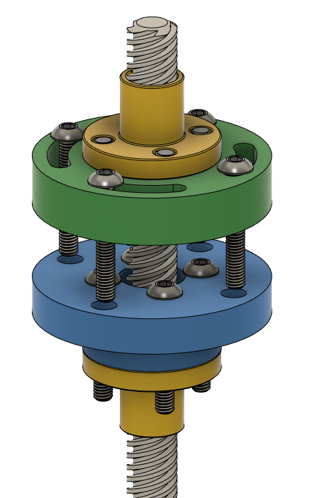
So, I’m just about done with some major upgrades to the MPCNC, including this technique Shane from SMH recommended using two TR8 nuts and 3d printed adapter plates. I was able to adjust the preload extremely precisely and there is NO noticeable play in the lead screw now. Like it’s crazy how stable it is while still being smooth to move (the two yellow parts are the TR8 nuts, the green and blue are plates attached to them).
You tighten the two sides together really tight, which pushes the plastic parts away from each other and binds them completely. Then you add the four screws and tighten slowly, which compresses the plastic enough to release the tension on the nuts. It was actually quite easy to find the right tension. I wouldn’t do this in PLA though, because of creep.
The problem now is that there’s a ton of backlash from the springy coupler! (top left in the video) I didn’t notice this before. Did I do something wrong putting it back together? So it is normally compressed, and pushing up on the bit as if it was drilling something hard stretches the coupler which is basically a spring. You can see the nut has zero play, but it feels like a lost cause unless I use a different kind of coupler.
EDIT: I really should’ve started a new thread for this.