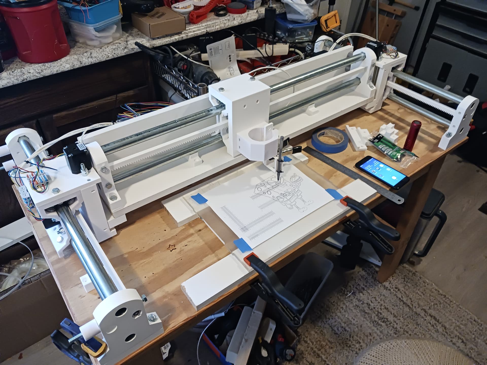
One of the many brilliant things about the LR4 design is that the Y rail is supported every so often, so overall deflection on the rail side of Y is mostly the mid-span deflection between each mount which is relatively small.
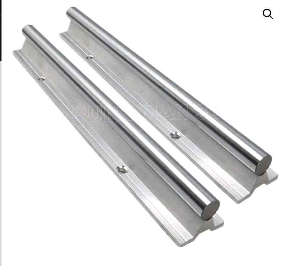
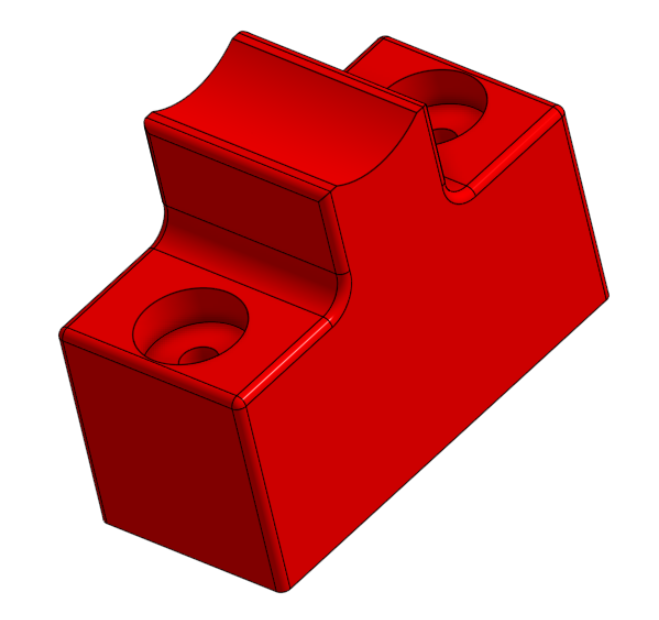
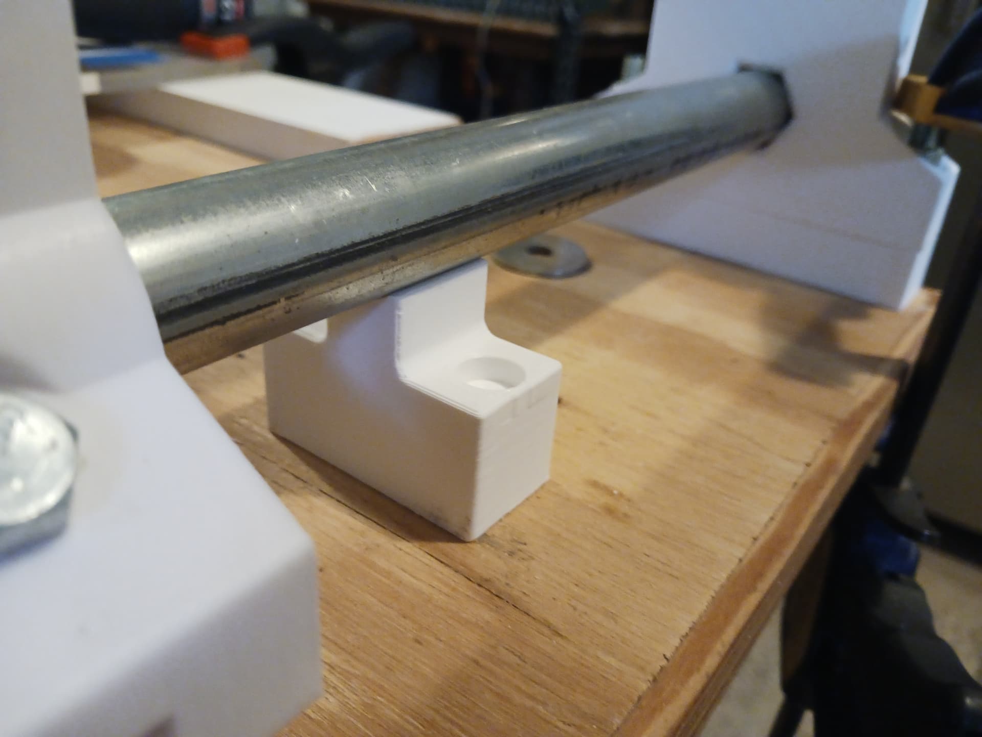
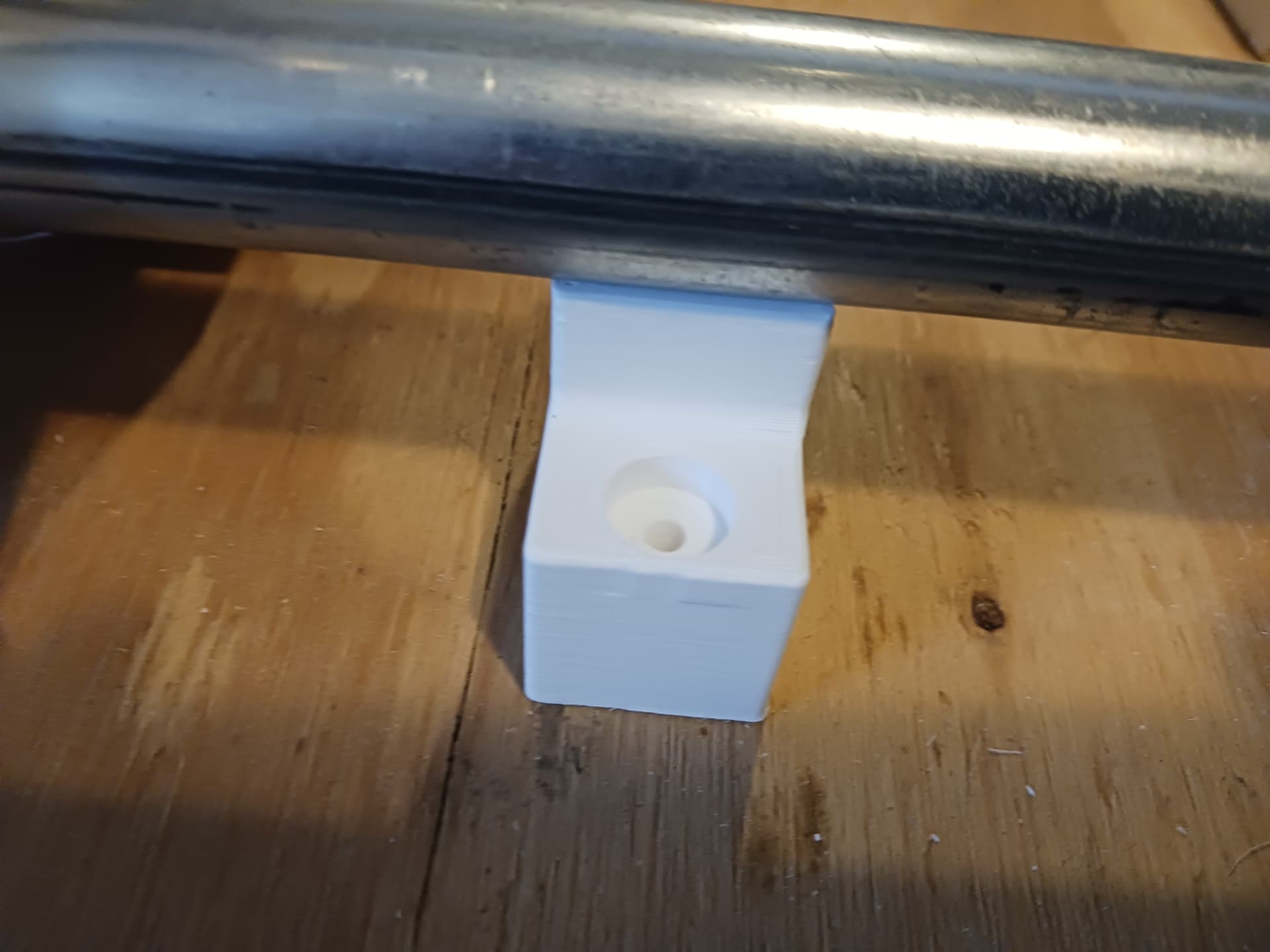
A similar effect for MPR&P could be had by making a small support that matches the circumfrence of the EMT on one side and then comes down to mount square to the table. It would be an add-on part, essentially free stiffening if using a longer span on the longer Y axis.
I also spent some time thinking again about end stop position I think they should have mounting holes on each of the trucks… still thinking about where.
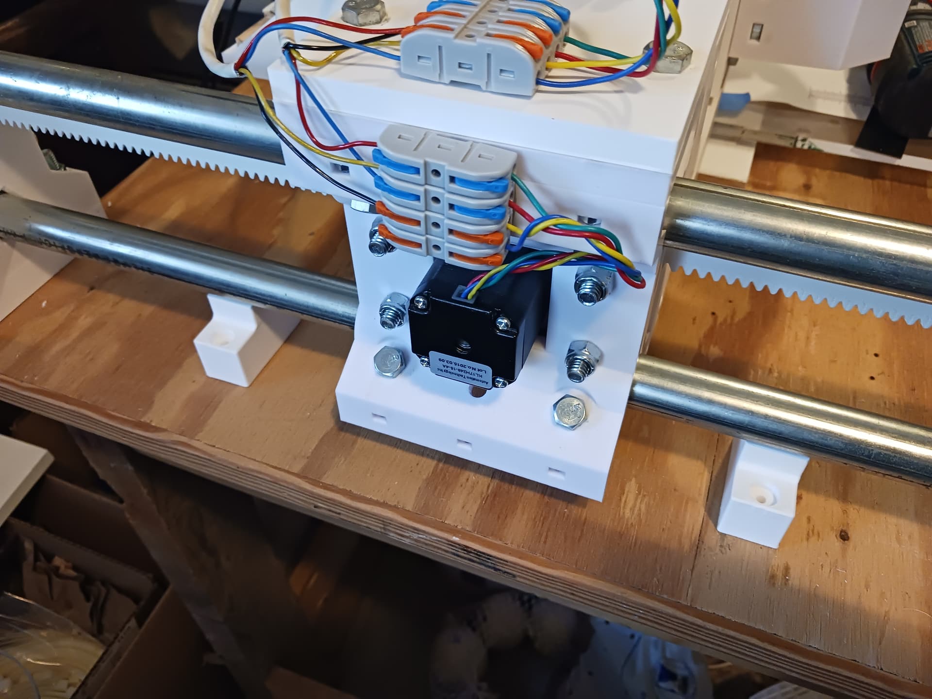
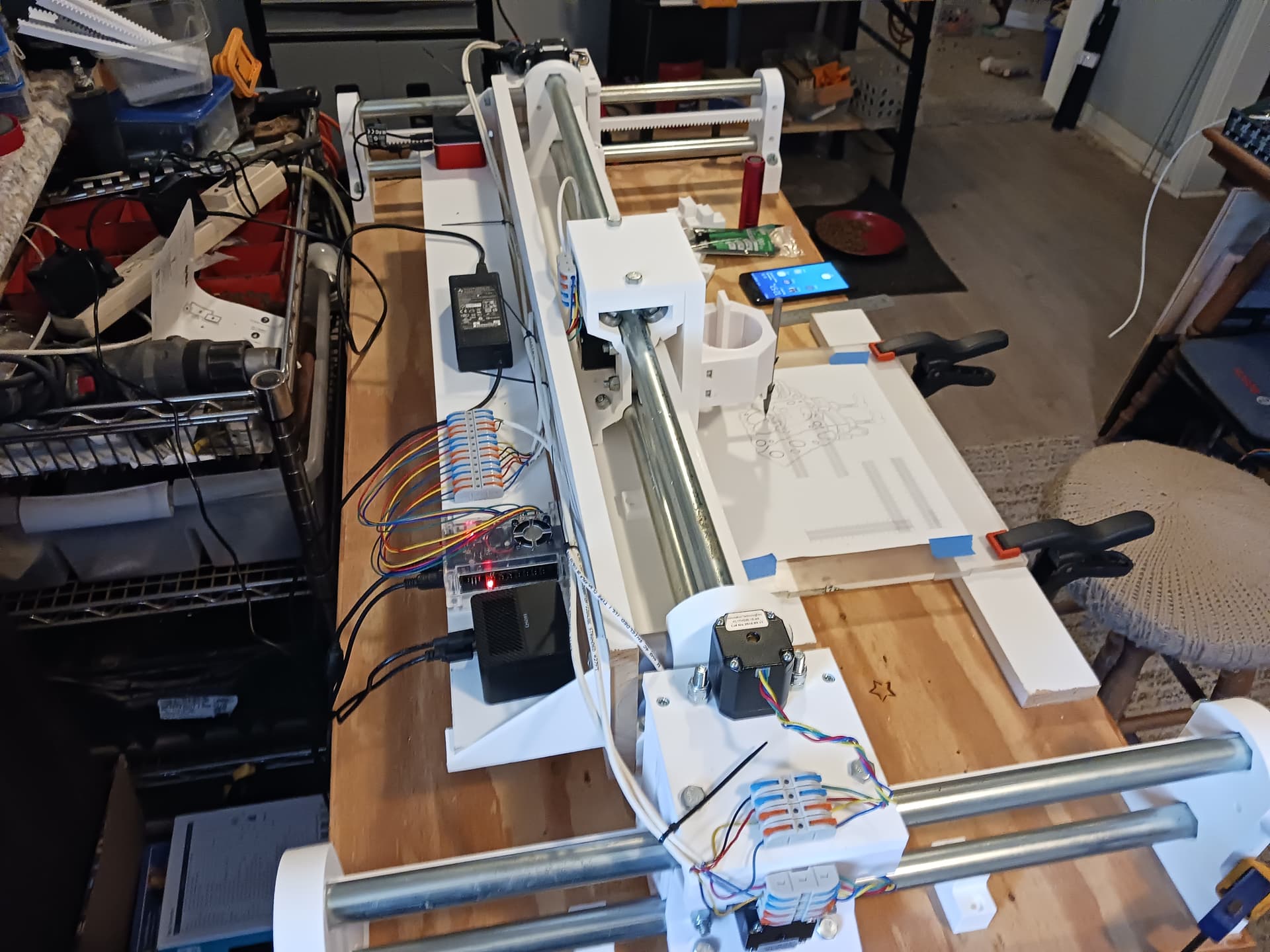
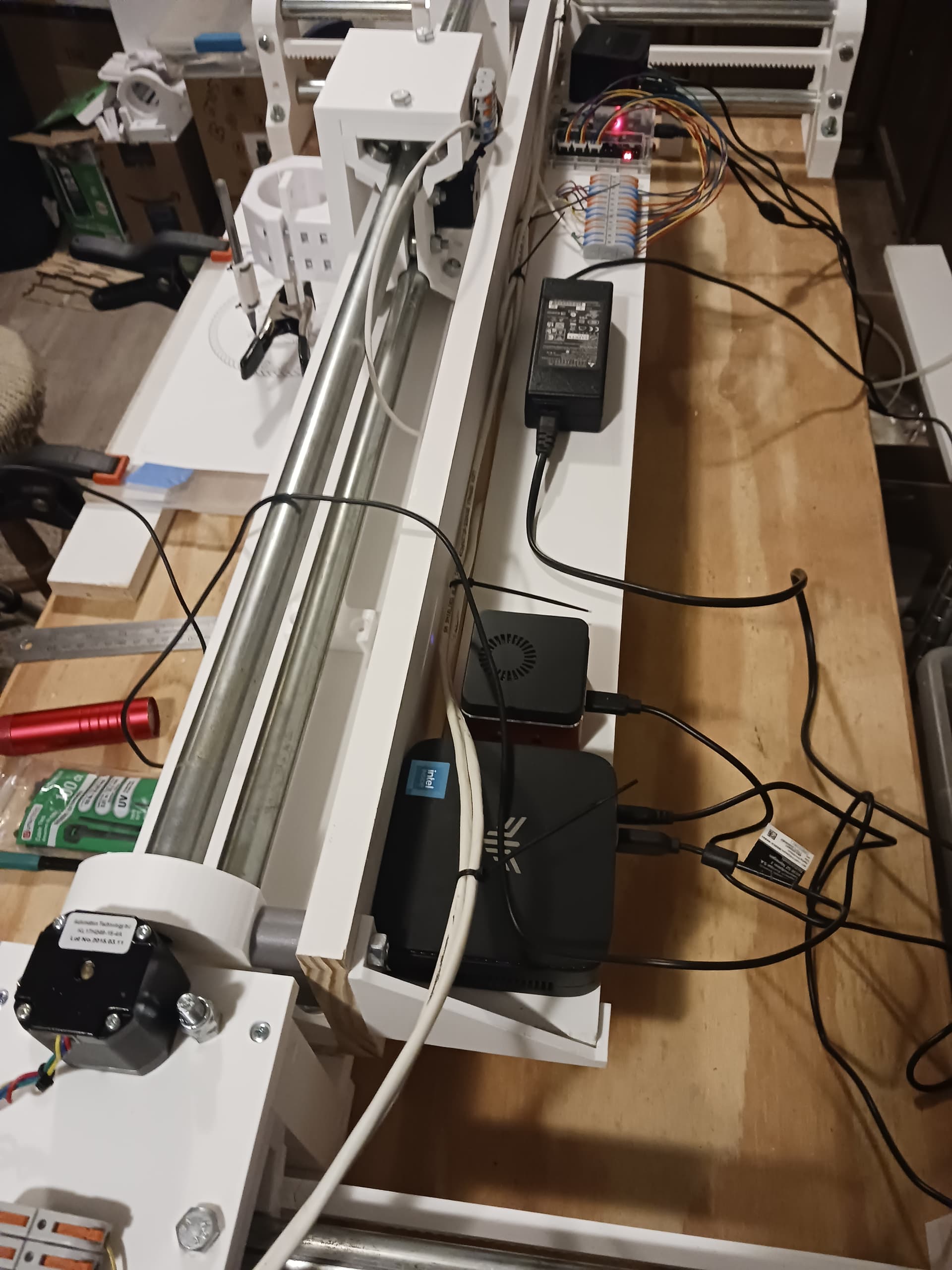
The smaller miniPC beside the larger one at bottom of picture didn’t really have enough horsepower to do good video. The larger one was much better. Now I need to figure out where to mount the webcam…
Aza, I just saw your comment on one of my YT videos and replied there. The cellphone pendant function is UGS Platform. I like the nice DRO and bigger buttons for my shaky fingers.
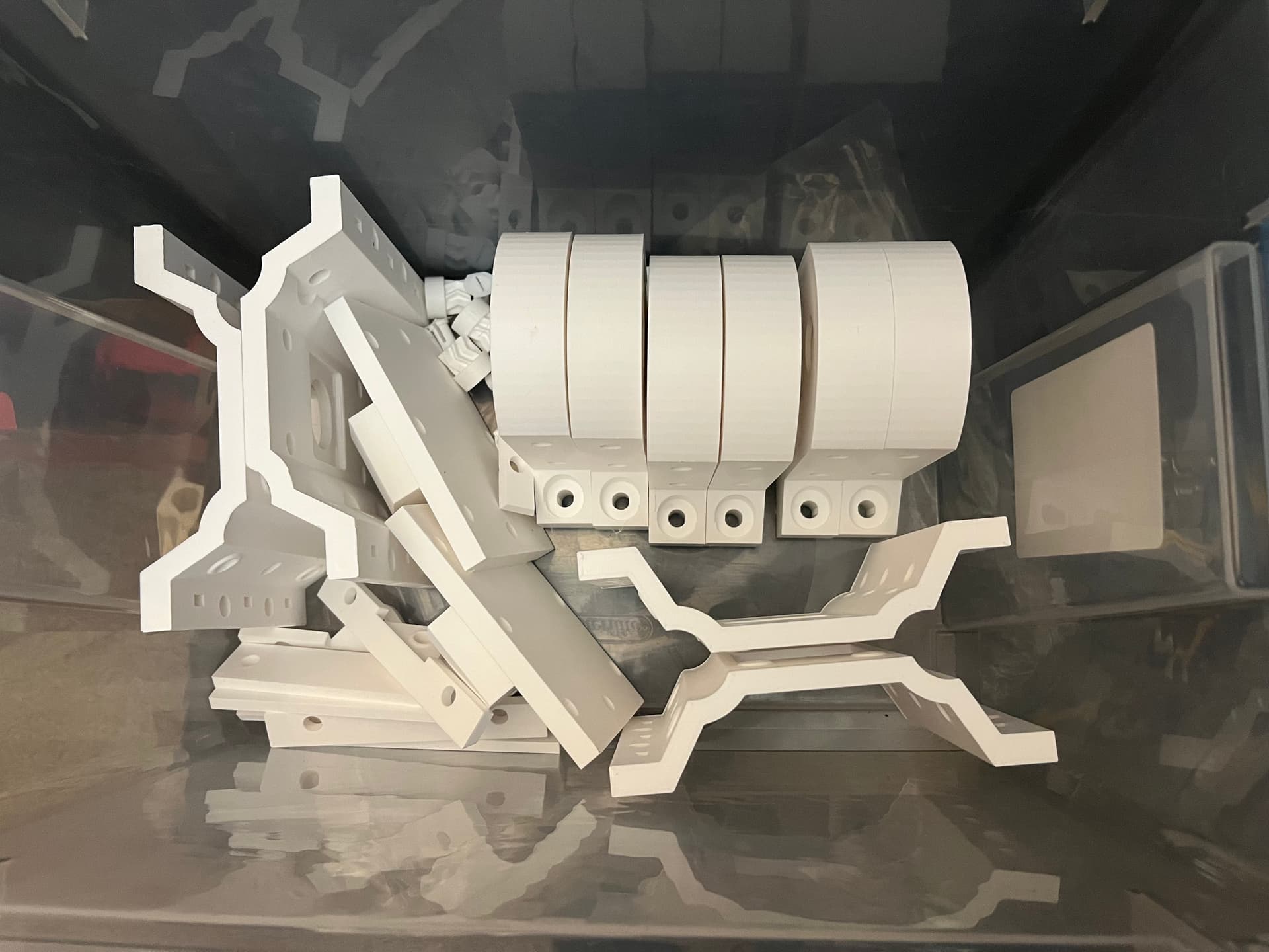
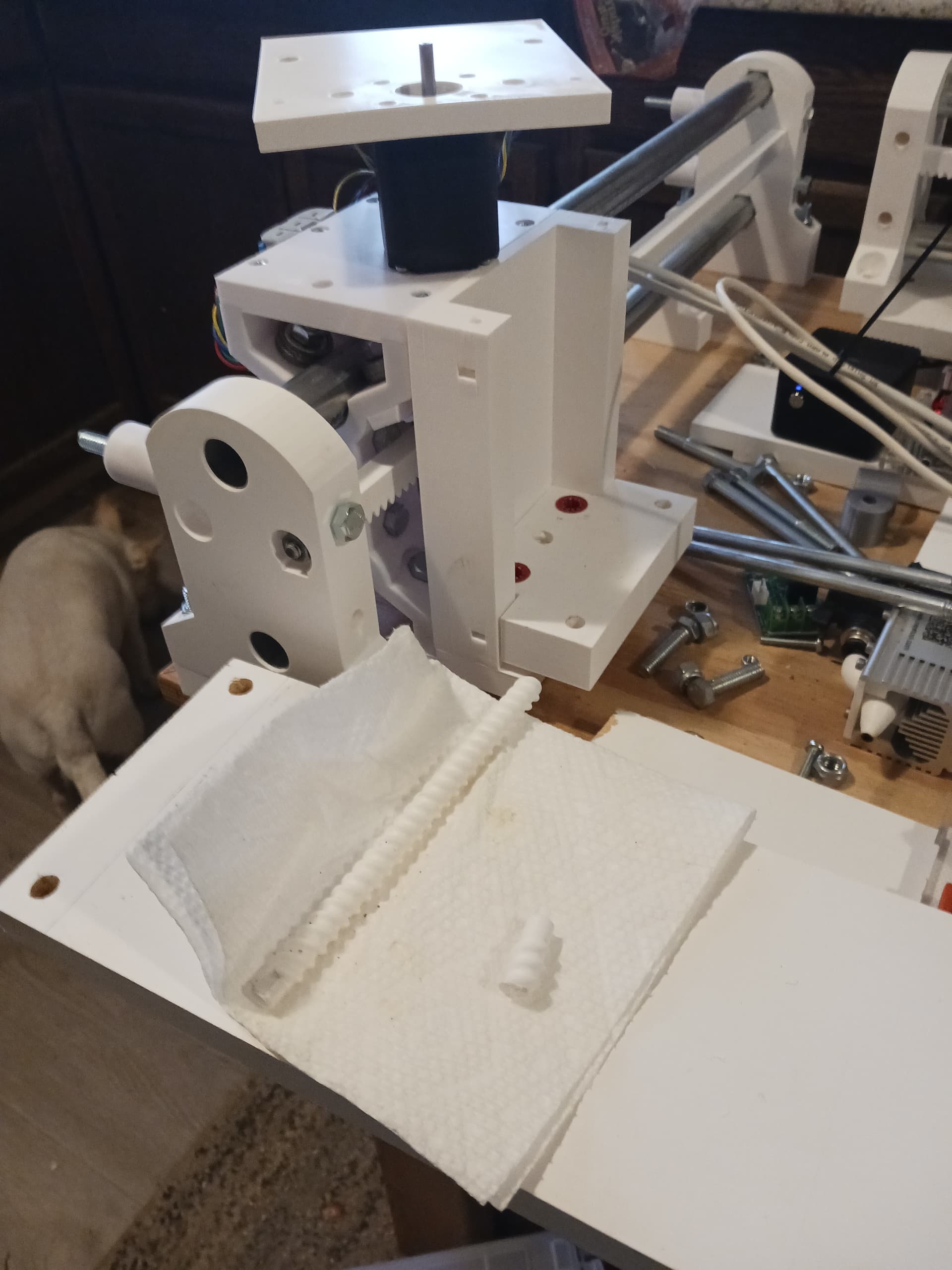
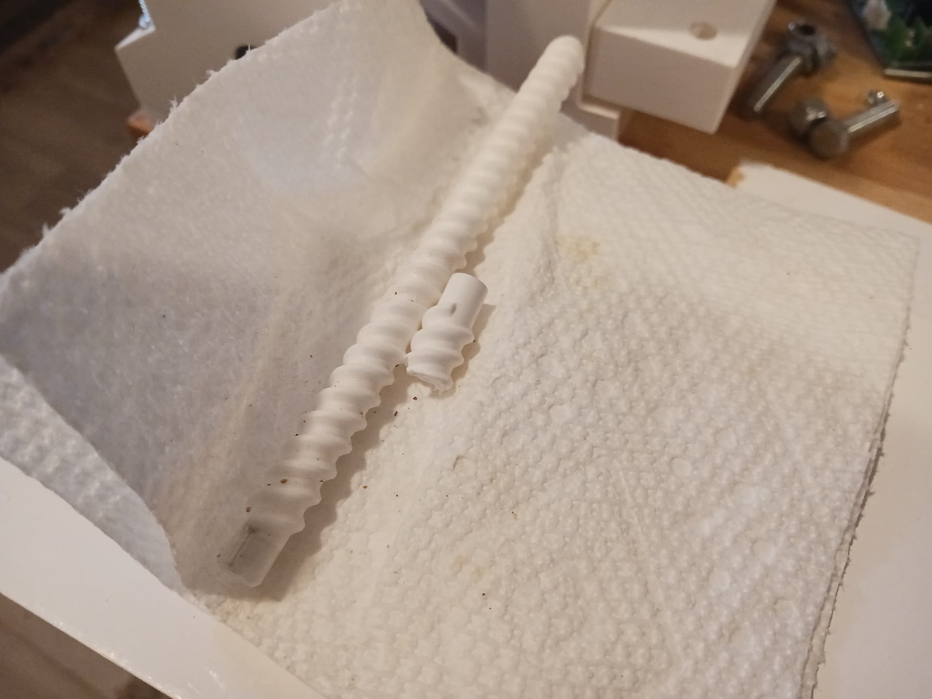
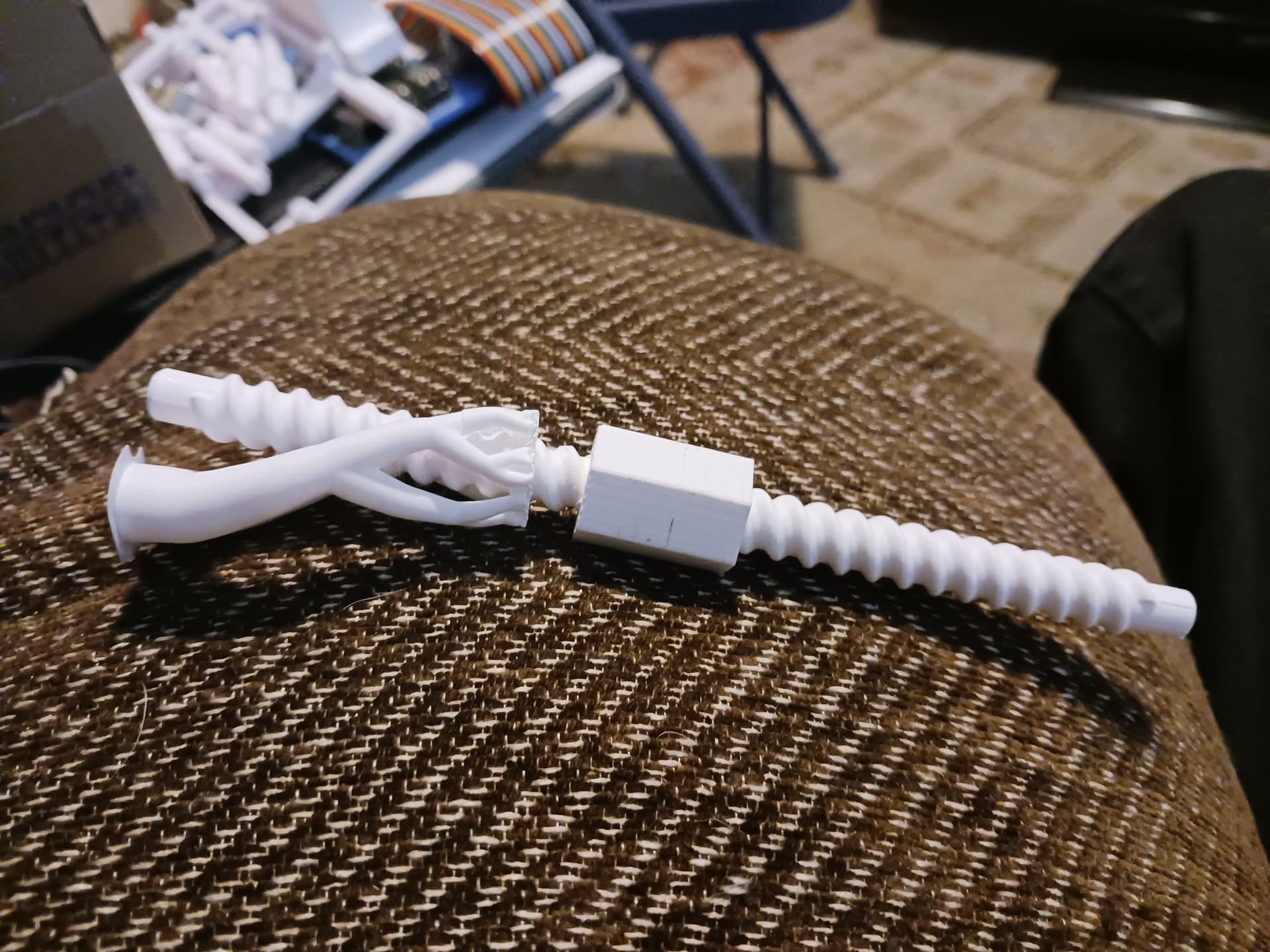
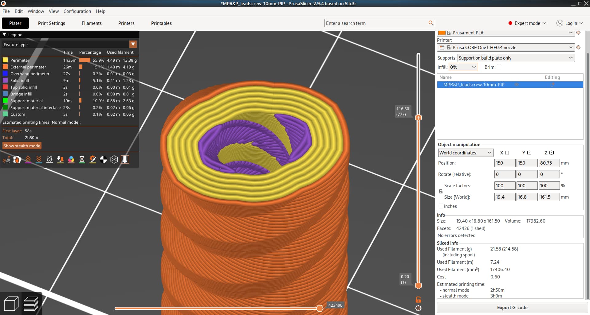
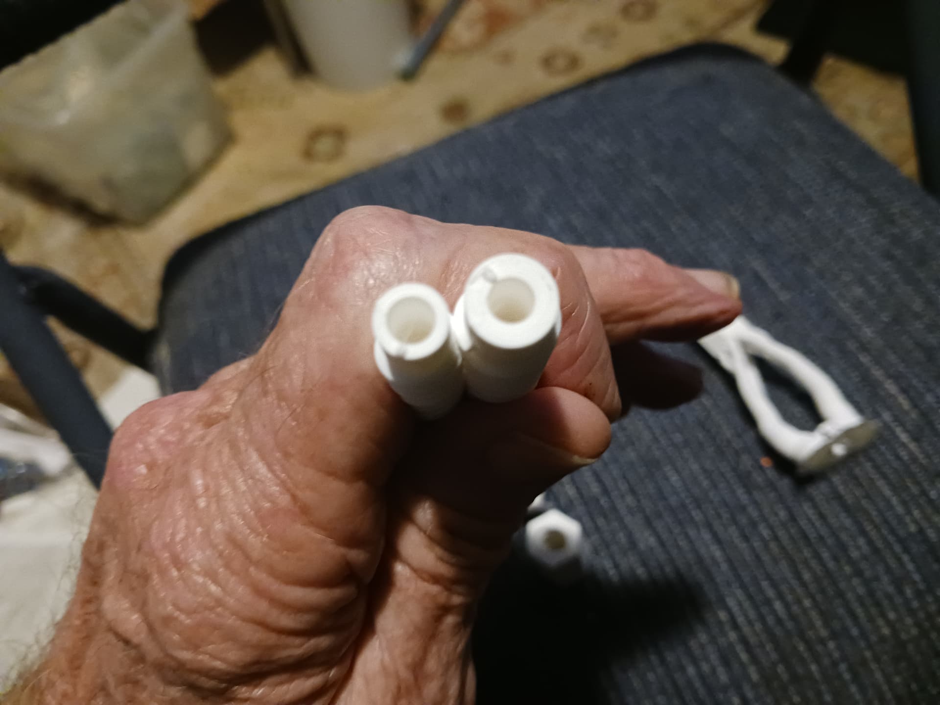
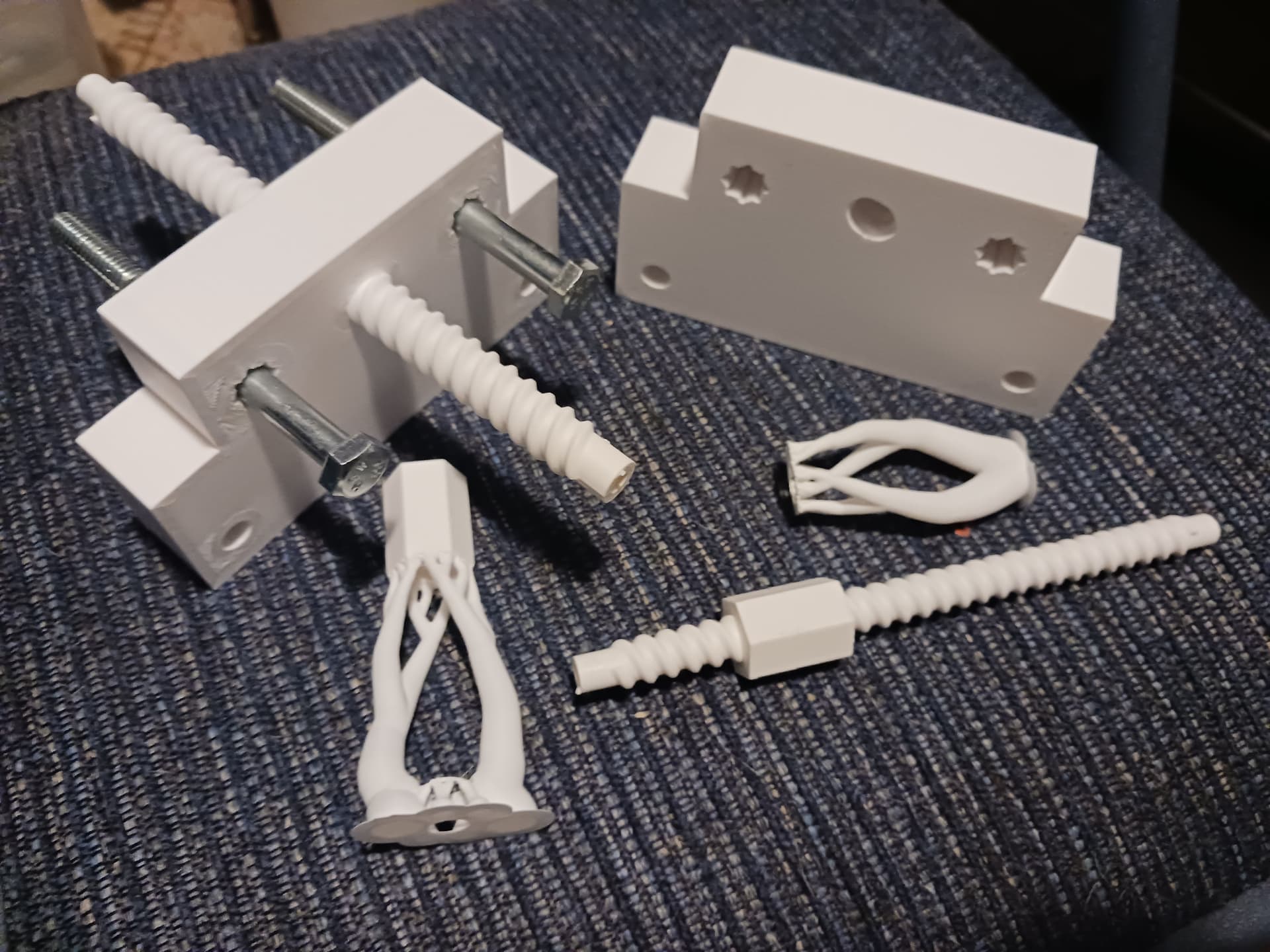
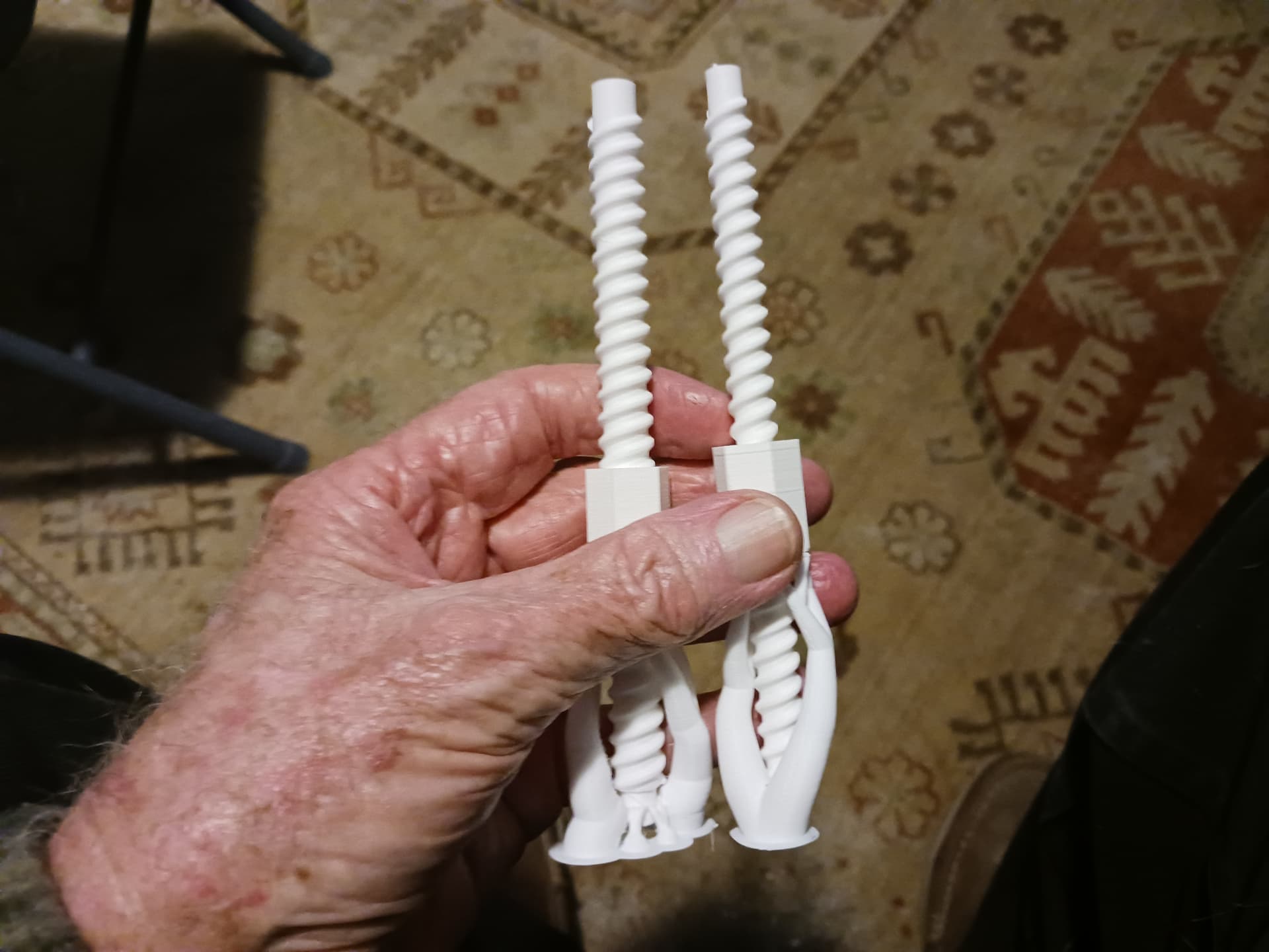
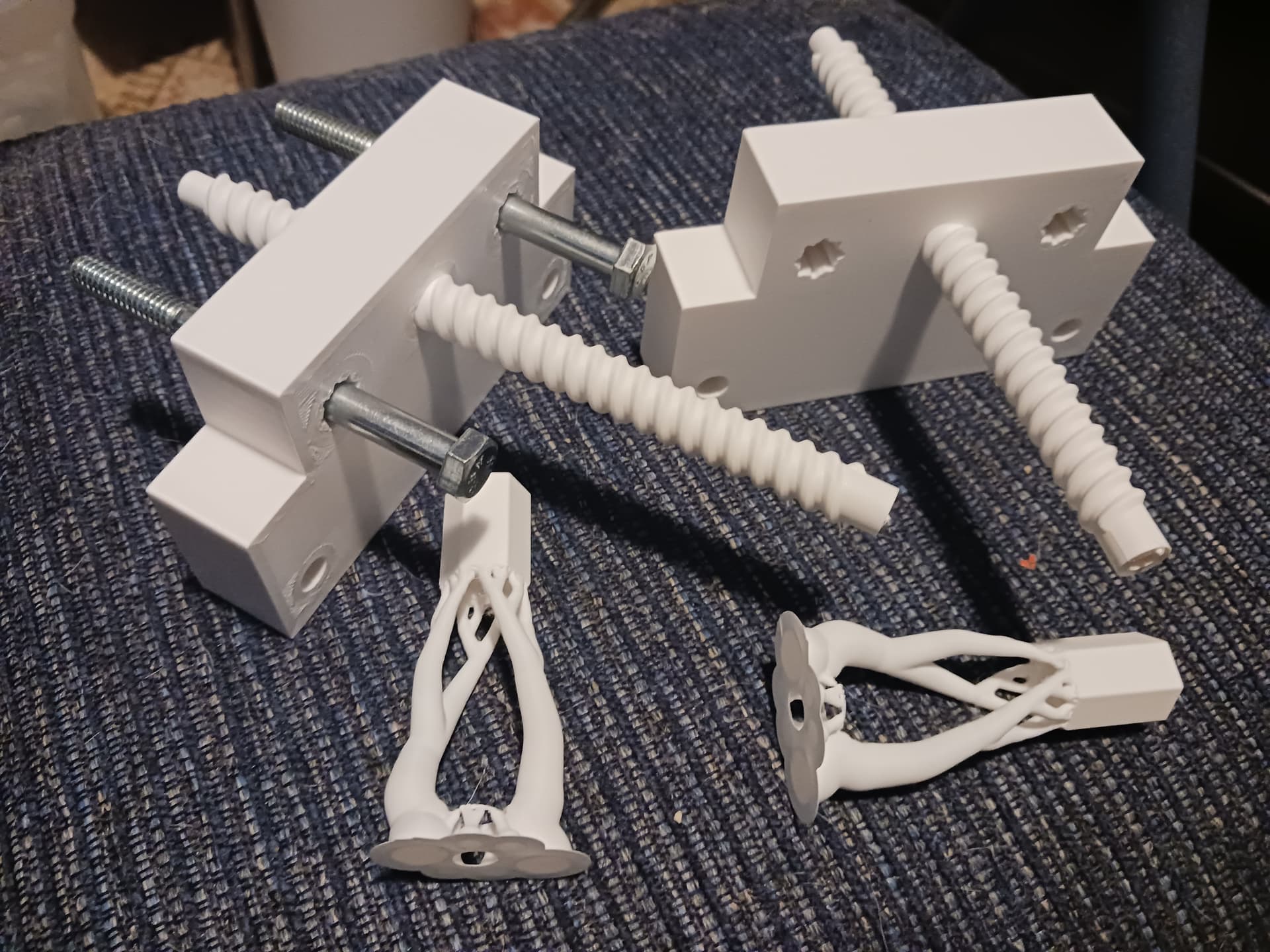
Not sure when or why the printed leadscrew on one side broke… but it did. This could be the first obvious mistake of using PLA+ rather than PLA before I knew better… I just put some plain PLA on order. At first I thought it might have broken where I put the little “pips” that you have to break after printing-in-place… but those are at the bearing end rather than the motor end, so that’s not it. Or, it could be I just need to increase the diameter of the leadscrew body from 8mm to 10mm to increase the amount of “meat” surrounding the shaft of the motor.
It’s an inexpensive repair, however… and I’ve already got another leadscrew printed. It’s a bit of a pain to disassemble and replace… but I figure that’s just the price you pay when trying new stuff and designing from the seat of your pants.
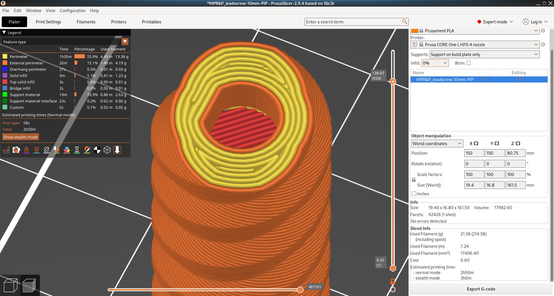
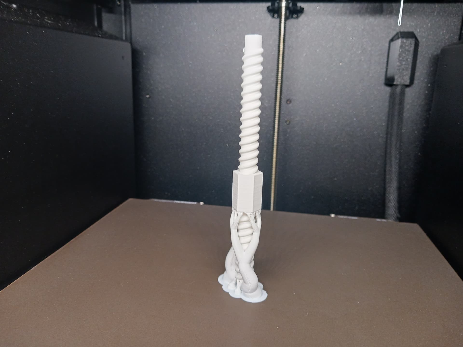
I probably will get back into Onshape and increase the diameter to make the leadscrew body a little more robust. It takes a firm straight push to get it started and seat it on the motor’s D-shaft when assembling… and since it prints vertically, any out of line force could easily wreck it on a layer line. I’ve been a bit surprised that they are as sturdy as they are… but I suppose they could always be a little more so.
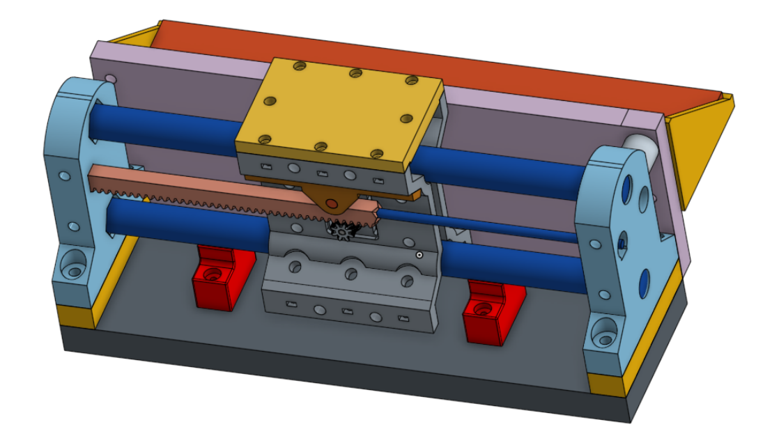
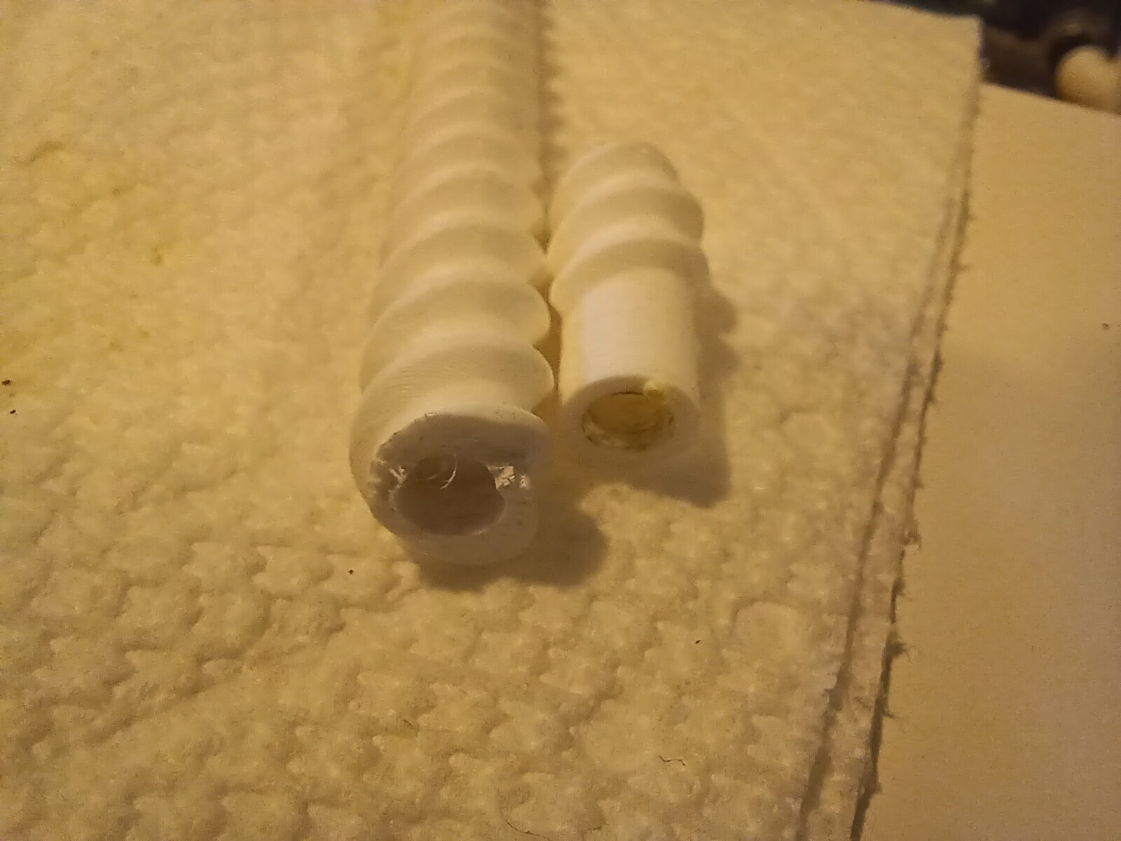
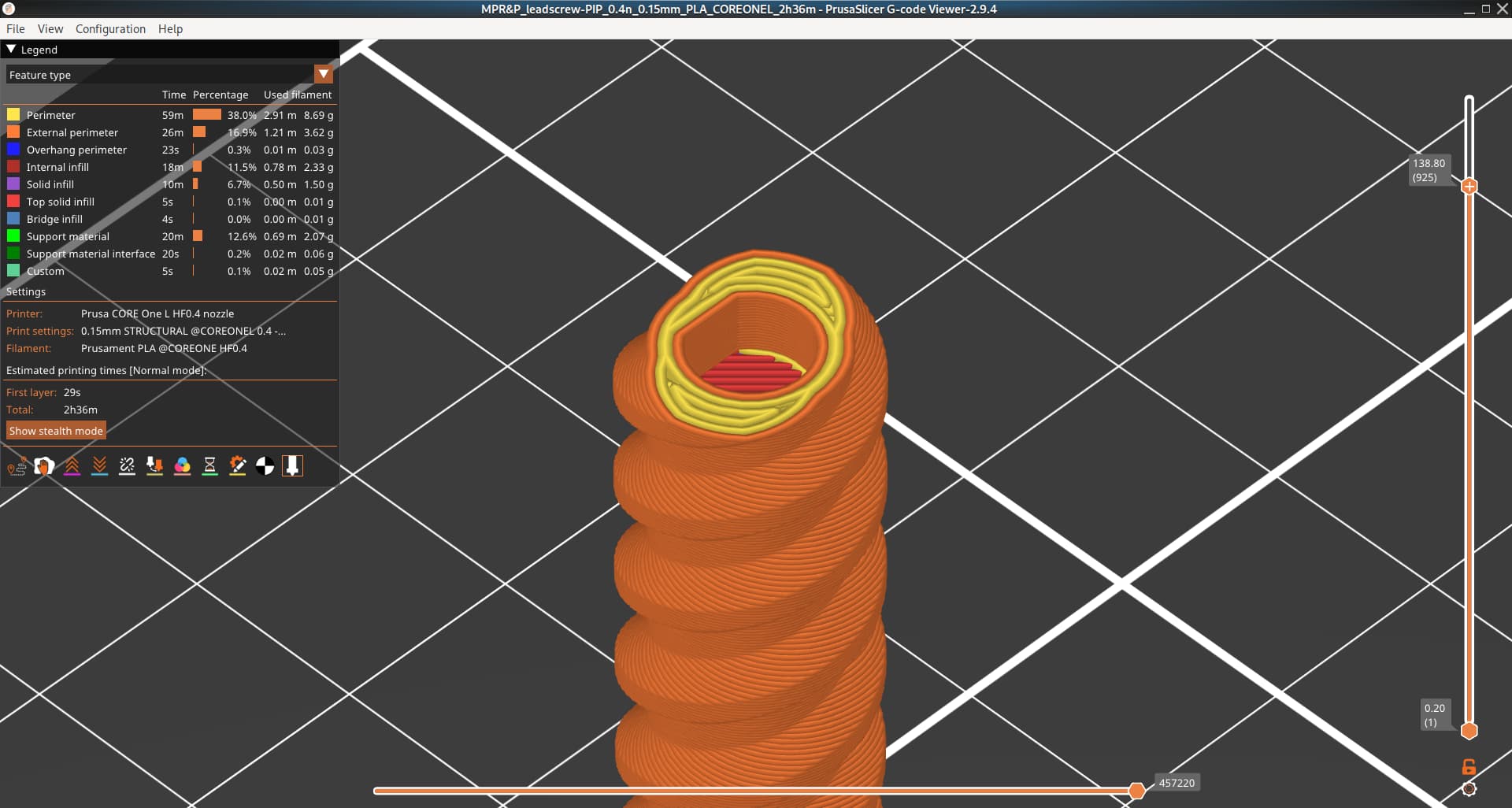
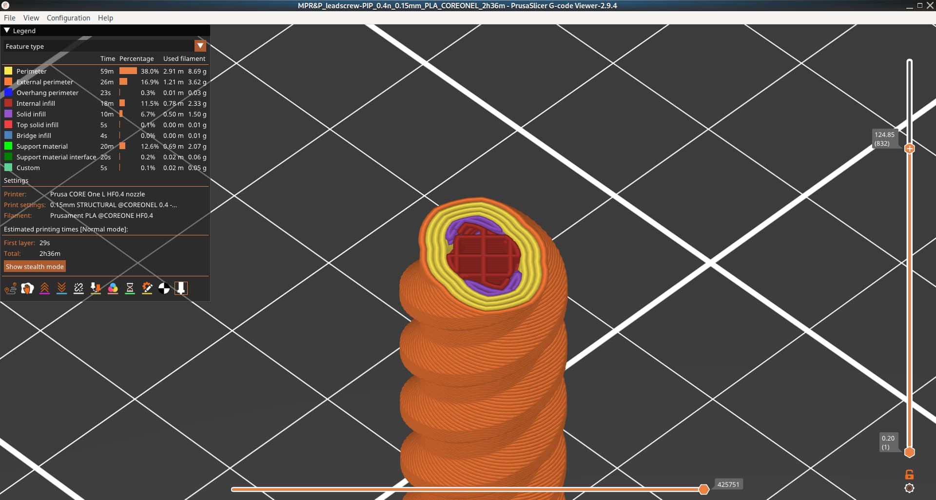
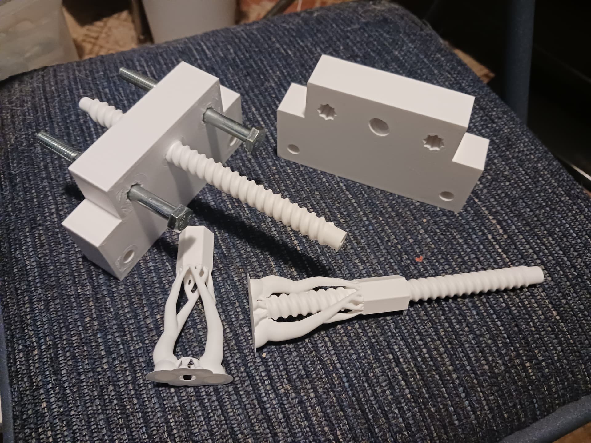
I don’t have an actual photo but I do have the .bgcode file. I’ve been printing the leadscrew with 4 perimeters and 50% infill and .15mm layer height. The break actually occurred in the D-shaped hollow near the end of the motor shaft… about here:
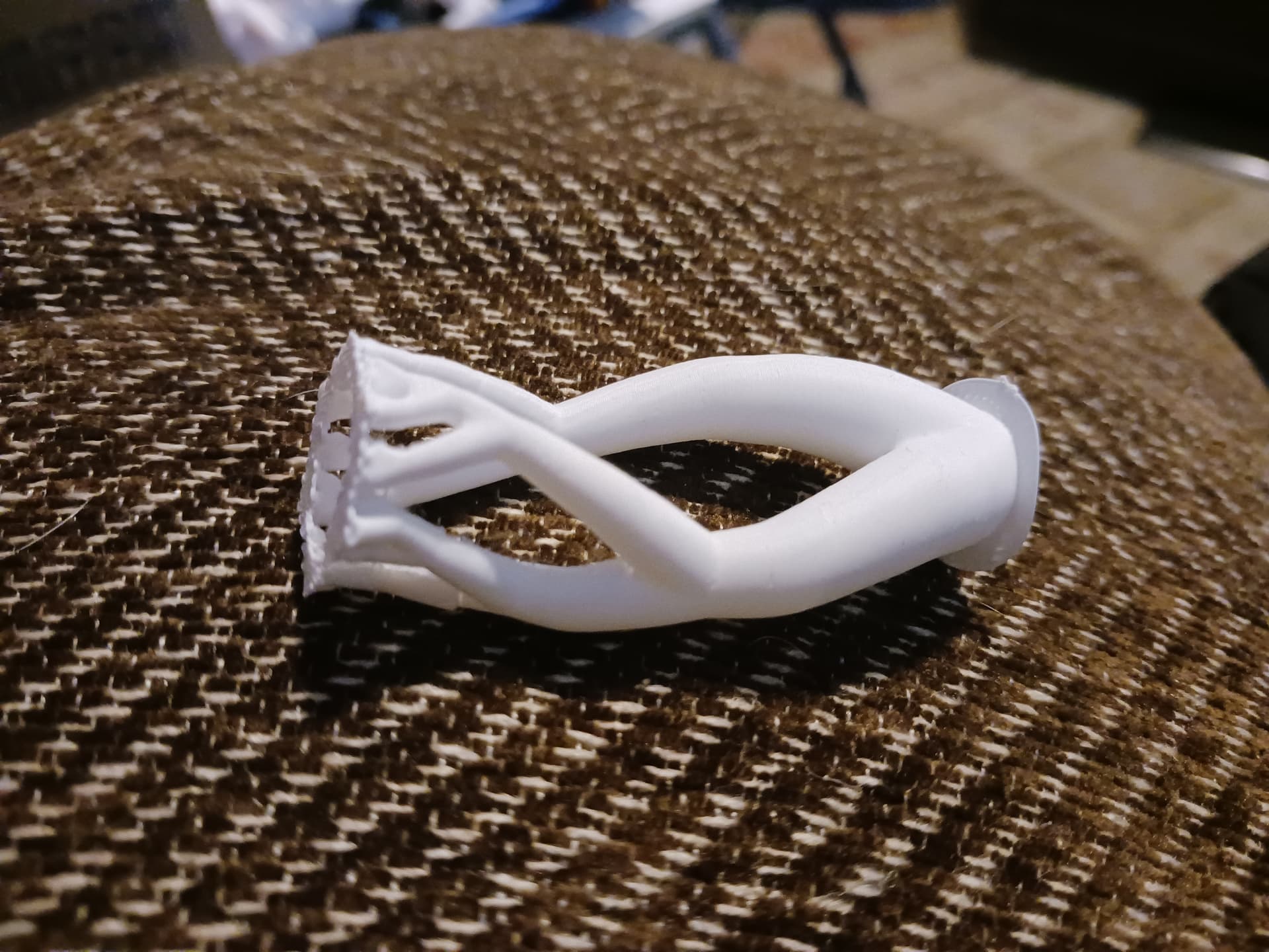
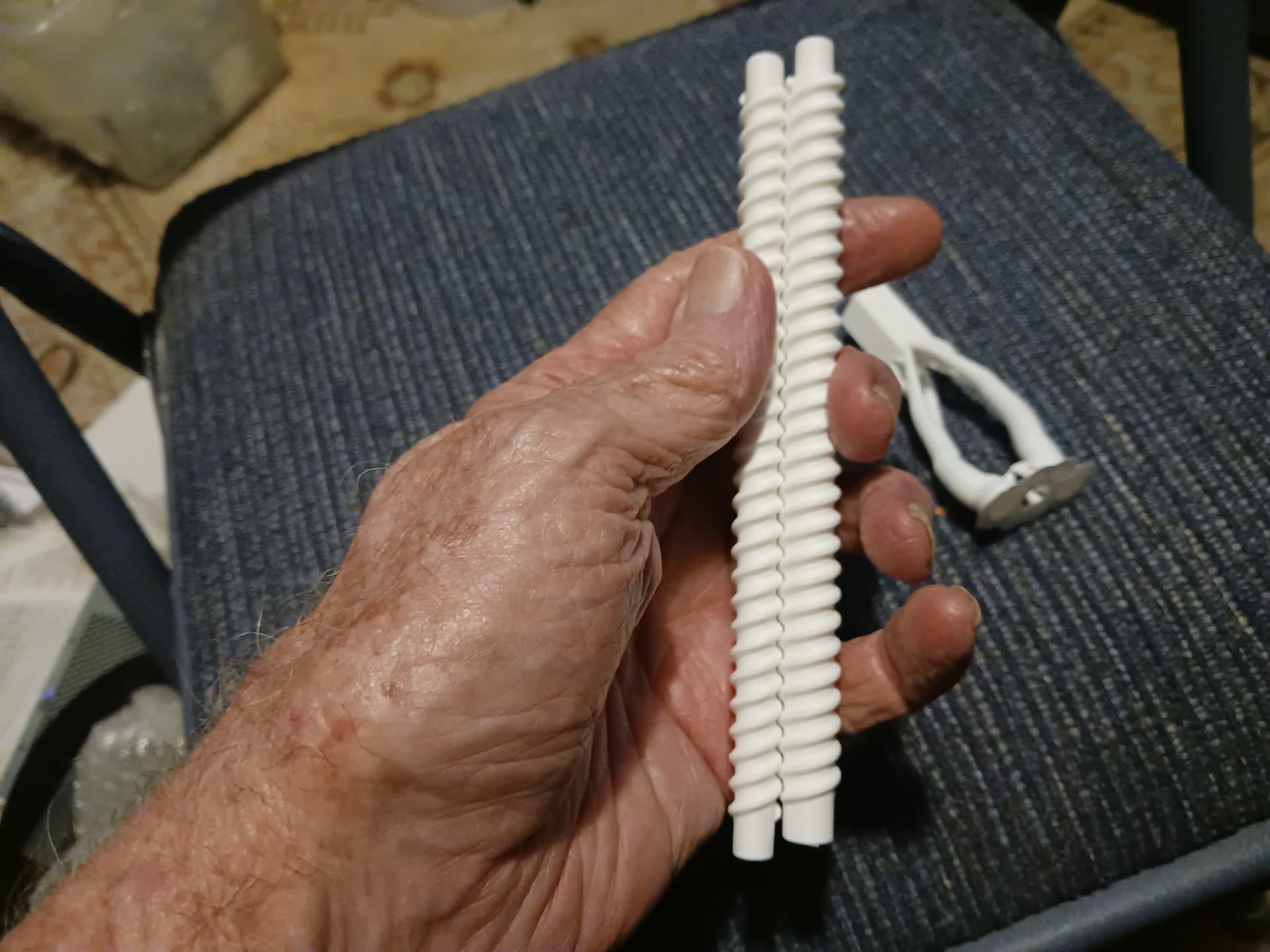
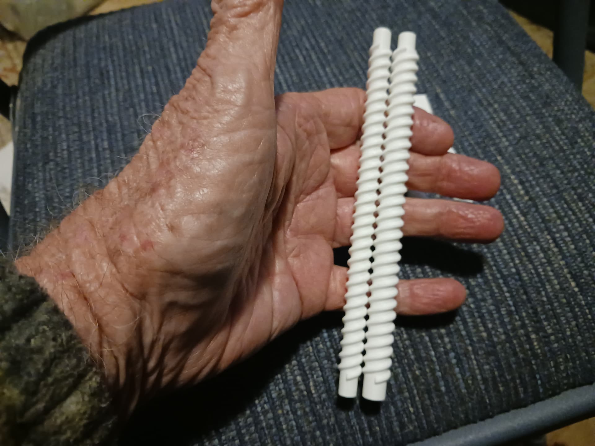
Comparing the broken leadscrew against a commercial metal ruler… it appears to be straight all the way round. It is also printed vertically on a new and pretty high-end Prusa Core One L printer. I’m sure it’s just the optical illusion of a “panoramic” view of a longish object at short range.
But you’re right… it was and will be side forces that will break the shaft, if anything. This is an early prototype machine and there is still a bit more slop in the Z-lift subassemblies than I’d like. I have already adjusted the CAD to increase the leadscrew diameter from 8mm to 10mm and am printing new parts right now.
That looks great! Since we both have Core One L printers, send me over your Prusa project for that leadscrew and I’ll fire off some test prints of my own.