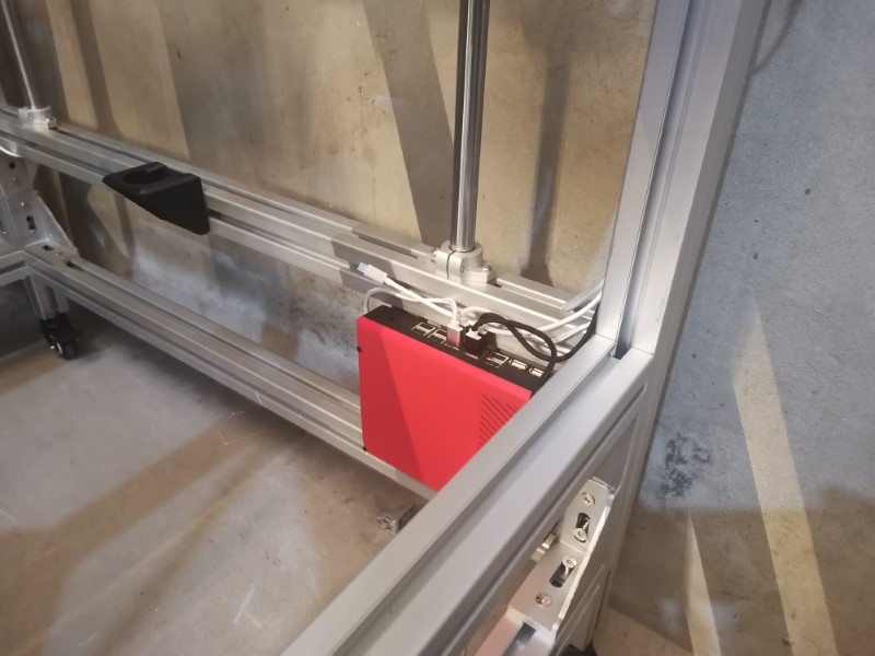
That controller box looks really good. Wow.
1 Like
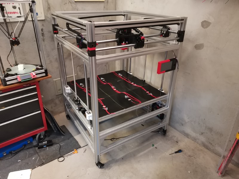
Great news: the crazy machine made its first moves on all axis!
So, first I had to make the Duet work. It wasn’t particularily difficult, but I had a few trouble at first because the supplier I got it from installed a very old version of the firmware for some reason, which took me a really long time to figure out and correct.
In case you’re wondering what a Duet is: this board is kinda next level stuff: you can control everything from your compter/phone/tablet remotely, using the browser. Kind of like octoprint, but it seems to be easier to use. It features some really great stuff, like the fact that you can change things like your stepper direction, driver currents, steps per mm and basically everything that would normally be present in the Marlin “configuration.h” file in just a few clicks!
It also features more drivers protections, which is a good thing otherwise I would probably had fried tthem already. It seems like you can disconnect the steppers without too much risk. You’ll even get an alert if one stepper phase is disconnected or doesn’t work properly!
So far I find it really awesome, the wifi connexion is stable and very responsive too, no delay whatsoever. It was a bit expensive, but so far I find it worth every penny.
Still a lot more to experiment on this though, let’s wait until it prints before getting too enthusiastic!
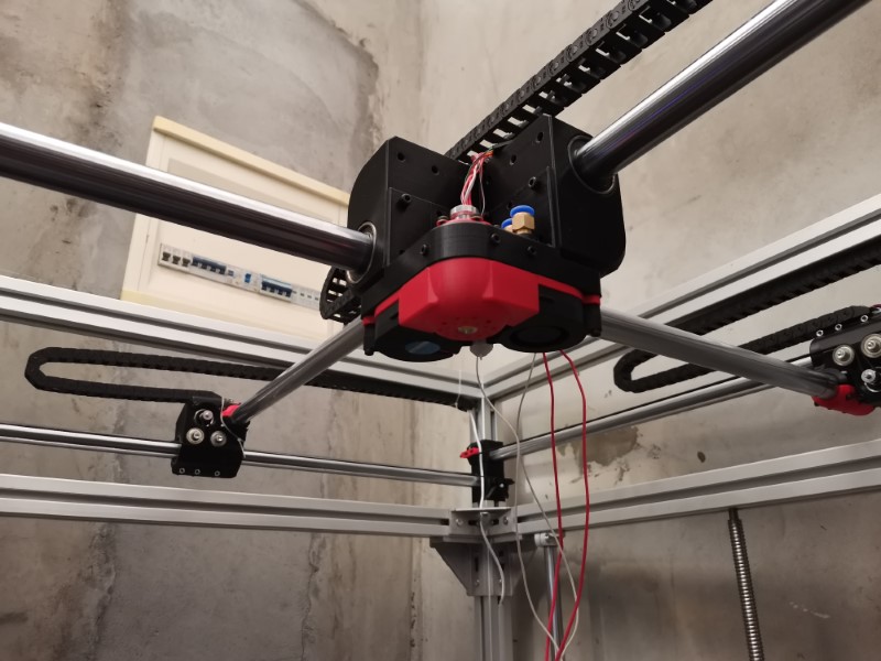
Anyway, I installed the enclosure here and made sure the wires could physically connect to it. So far so good!
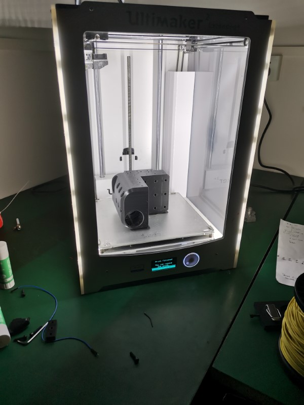
Also printed the central carriage. This thing is massive, it took litterally more than half a spool of plastic to print (550g according to my slicer)! It was printed with a 50% infill and 5 loops and took about 22 hours to print. Used the ultimaker at work to hopefully get it squared better than my delta printers could:
Weird thing is, after installing it in the frame it looks tiny:
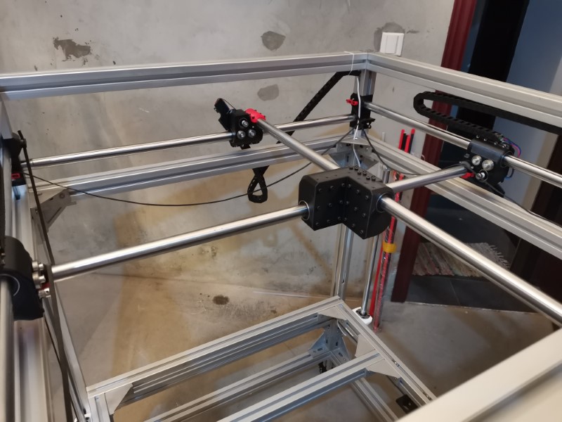
Total weight including the linear bearings and the screws was measured at 1.3kg… That will have some inertia for sure… Hope it won’t be an issue, but I guess it will be similar to when I had this giant Z axis moving around before.
So anyway, I finally received my ball screws, so at first I installed just one because I had to wait for a second belt to arrive:
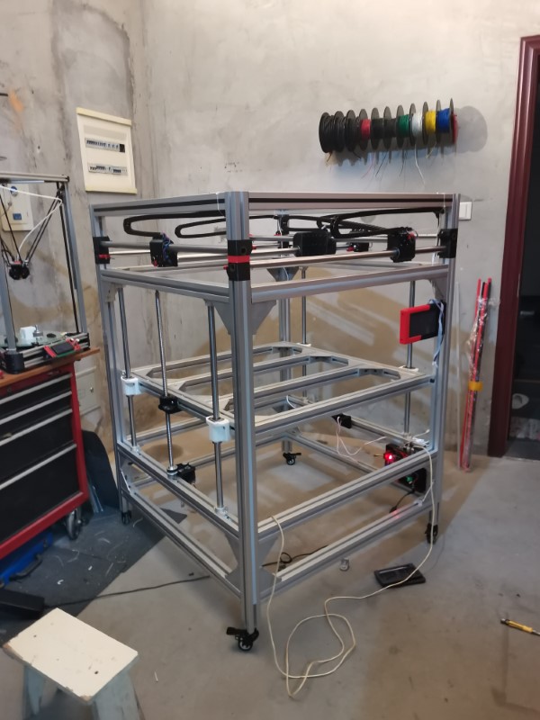
…But in the end, I couldn’t really wait so I just gave it a quick shot, just to see if it had a chance to work… And as it turned out, it worked well behond my expectations: One relatively small nema 23 stepper was enough to lift the whole bed structure with really decent speed!!

So that’s really great news for me, adding an other motor will double the power which should be more than enough to lift the whole thing with the added weights of the bed, glass and everything!
The other axis are much more silent and they are fast and responsive too.
Next step is to design a print head system and start working on the bed.
16 Likes
Nice! Are you using Marlin 2.0 or something else?
1 Like
No, I think it’s using something like reprap 2.xx or maybe 3.xx firmware. So far it seems nice.
That was my biggest fear actually, having to ditch Marlin.
Now that I think about it, I need to check if my slicer is compatible with it, I’d hate to have to ditch my good ol’ kisslicer, not a big fan of the other ones.
Currently building a CoreXY printer as well but not thaaaat big! 
Really nice work so far!
1 Like
Reprap firmware is good, just need to get your head around the fact it’s almost entirely Gcode, even the setup.
1 Like
No heated bed? Or are you going to use multiple of heatpads?
The bed will be heated, that is not optional on such large machines, you get a lot of warping otherwise. So far my plan is to buy a large aluminum plate and probably use several silicon heat pads. Not entirely sure yet, I need to finish designing my print head first and then I’ll start tackling the bed.
I find this solution to have several advantages: a large thick plate of aluminum should be rigid, transfers heat well so it should remain uniformly heated and it is not as expensive as I thought it would be. Using several heat pads instead of a single large one means I should be able to install some adjusting screws all over the plate to correct its flatness in the middle as well as the sides. I see very few downsides aside from weight, which hopefully won’t be an issue. And even if it turns out to be an issue, I can overcome it by using larger motors with external drivers.
I don’t want to cut corners on this machine to save a few bucks, this time I intend to do it right!
Keenovo (I think I’ll buy my heating pad there) can make custom silicone heating pads, or on AliExpress for instance you can write the sellers if they can customize their pads as well.
But I think for that bed size you’ll need some Watts… 
1 Like
Yea, that’s who makes my heater as well. Works beautifully. Still on the fence on whether I should physically attach the heater, or keep relying on the adhesive. It’s an acrylic adhesive, which I’ve read that gets stronger the hotter it gets, so  . Mine is 110 with a ssr doing the switching off the heat bed pins on the duet.
I’ll go with 220V. Respective SSR is already installed but the rest is missing…
Since you have a mill, then you can mill out a channel, add a gasket and a back plate, and pump hot water or glycol through it.
I’ve never seen anyone do that for a 3d printer, probably because it’s a bad idea.
Not really hot enough.
Sounds really hard to build in practice though in theory I guess it should work and be relatively fast. Plus I don’t have a mill, I only have a small 3040 CNC, can’t mill something that big 
I’m already having a really hard time designing a new version of my water cooled print head, don’t really want to mess with other liquids again 
1 Like
Weaksauce… The power of a dying star! Now that’s how you heat something up! Bonus points for a little Chris Hemsworth figure to open and close the valve… ![]()
![]()
![]()
![]()
That’s been tried.
Made the news too.
Maybe you heard of it…
Chernobyl ring a bell?
If you put magnets in your heated bed and use a steel sheet like a prusa instead of entirely removing such a large and easily bent sheet you could use a thin bar that slides under to remove prints?
Hi guys!
A few updates:
-I ordered and received the heating system for my bed: it will be nine silicon heating pads of 300x300mm and 300W each, so around 2700W ! So that should be plenty of power, if my calculations are correct it should take around 4 minutes to heat the big aluminum plate I’m planning to use as a bed.
Each heating pad comes with its own temperature sensor, I’m wondering what to do with this. I’d like to be able to monitor each one individually, but I don’t know if and how this might be possible. I’m afraid otherwise I might get some temperature inconsistencies, especially if one or a few pads are more powerful than the others. I guess for now I’ll just parallell everything and use only one sensor, but it’d be nice to have a solution for that later.
Anyway, I have to design my aluminum plate system, so far I plan on going for a classic yet proven design, using springs and adjusting screws. Plan is to install one every 30 cm or so to form a grid, this way I could adjust tilt and planeity.
Also thinking about what will be my printing surface. I do like glass, it works fine and it makes for a very smooth surface, but it can be really hard to separate the print from its surface sometimes, especially on large prints. So I’m wondering if I should try using the magnetic peel bed sheets. I don’t think I could find such large ones but I could just install them the same way I installed the heating pads. I’m not decided yet, I do like these magnetic sheets for peeling the print easily, but I find the adhesion to be inferior and also the surface finish it leaves on the part isn’t that great.
I guess I’ll start with using the glass anyway, since I already have it from my old build.
Also started building my extrusion system, and it wasn’t an easy one…
I wanted it to have the following characteristics:
-Very rigid, so the probe couldn’t be on the nozzle this time like I did on my previous builds.
-Decided to use the BL touch
-Water cooled nozzle, because for such large printers it really helps
-Good part cooling solution, this is usually the key to good looking prints
-Beefiest extrusion motor I could find, because it needs to extrude a lot and fast
-Best possible heating solution: powerful heating cartridge, full copper volcano heating block, steel nozzle for longevity, aerogel silica insultion
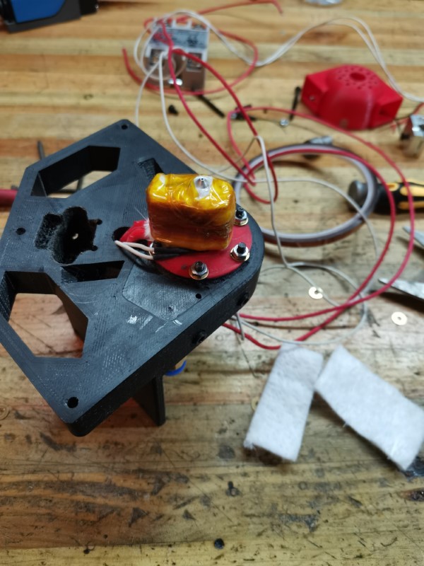
It was quite a challenge to try fitting all this in a small form factor. My solution isn’t perfect for sure, but I think it should work. So I have this main bracket that is attached to the gantry with twelve screws:
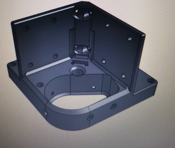
As you can see, there is a big oblong hole, this is where I’m sliding in place a little cooling block like this:
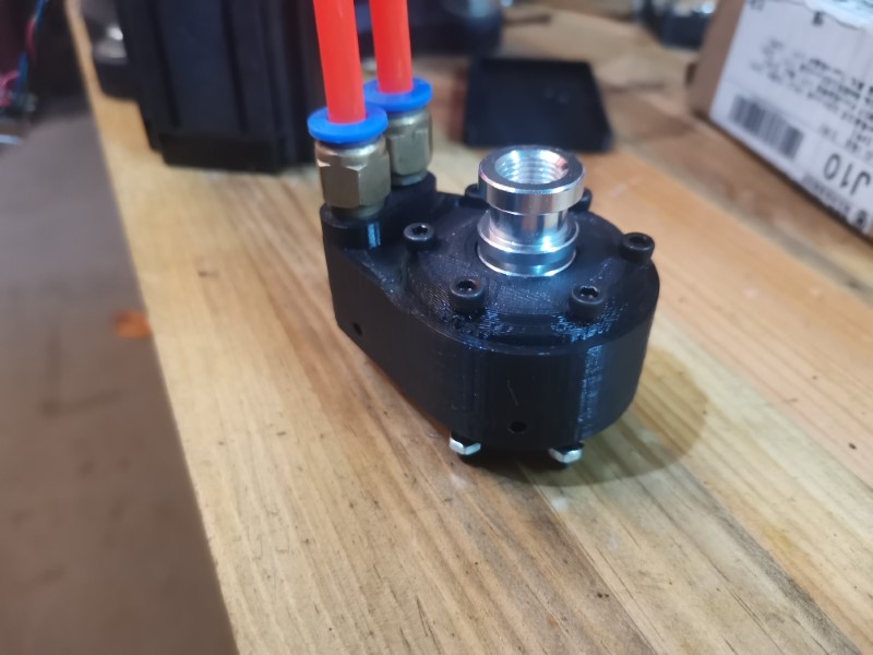
Reason for doing that is that it will be easier to switch from one nozzle assembly to another this way, plus it helped a lot with manufacturing the watercooled block in the first place: it’s easier to get a small watertight print than a large one. So I could print the bracket with a regular infill, while the little block has a 100% infill. Took me 3 prints to get it watertight though, even at 100% it does sometimes have a few tiny holes.
Installed the heating block:
Put some aerogel sheets around it and secured tightly with kapton tape:
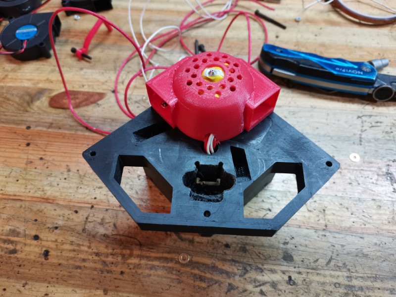
Attached the part cooling shroud. I’m not entirely sure this design will work fine, but I can easily tweak it later:
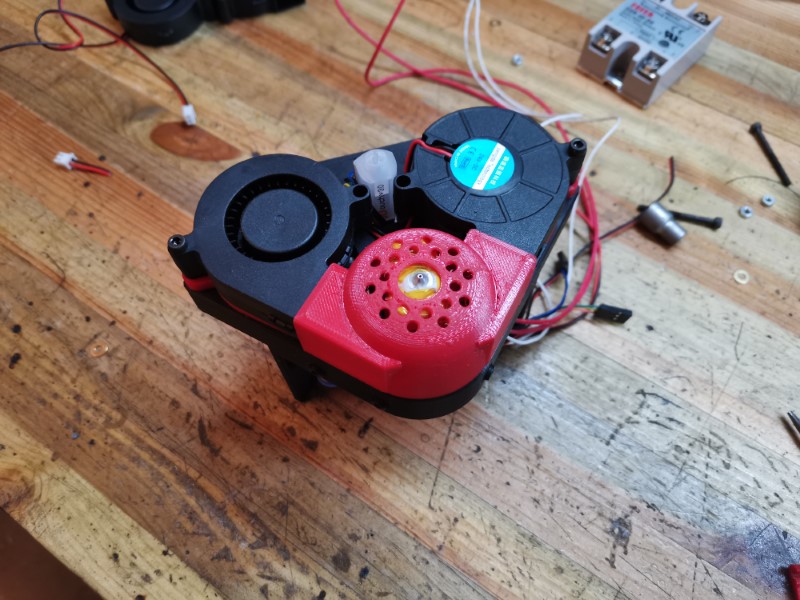
Added the two fans and the BL touch:
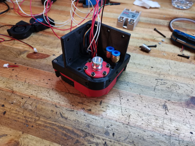
Installed on the carriage, seems to fit!
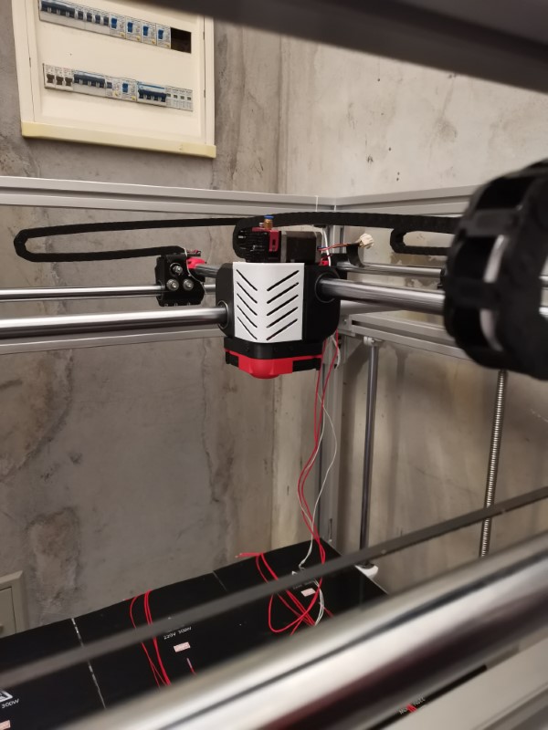
Made a first test for a cover, it’s purely for aesthetics to make it look a bit cleaner. Will be printed in black later.
Finally, I started working on my USB-C connector, I think I’ll be able to pass more than everything I need:
-Power for the cartridge (takes 8 pins)
-temp sensor (2 pins)
-BL touch (5 pins)
-Fan power (2 pins)
-LEDs (2 or 4 pins, depending on how much power they’ll draw)
I’ll still have 5 pins left so I could add some other crap later.
This is achieved at the expense of USB-C reversibility. Meaning there will be only one right way to plug the cable. So I’ll have to come with a system in order to never plug it the wrong way, I hope that’ll work!
That’s all for now!
9 Likes
You would need at least the minimum amount of logic for each eater. If the due can’t support that, then maybe you can get the temperature set point for the bed out the the due (or just set it seperately) and into another arduino. The code for bang bang control is trivial. If it’s too cold, turn it on. Too hot, turn it off. Then pause so you don’t end up toggling too fast. Reading the temperature is pretty simple, but I would just copy it from Marlin. Then you have each area have its own control. You might end up wanting to adjust each zone a little. I am not convinced the tempersture sensors are that correct in the absolute sense.
2.7kW is a lot. Like space heater hot. You should consider and enclosure just to make them more efficient, and to keep from heating your whole house.
2 Likes
Yeah, but that will only be used at full power during a few minutes until it reaches the setpoint. The rest of the time it won’t use nearly as much power, I estimate it should be something around 300W or even less after it reached 55 degree. The goal of having that much power is to be able to heat up quickly.
The old setup using the heated tile was only drawing 150W for the whole surface, that’s why it was taking really, really long to heat up and was not able to go higher than 45 C. I had to switch it on 45 minutes prior to any print, so it was a bit annoying, I try to avoid that now, I’d like it to be ready to print in less than 5 minutes, heating and autobed leveling included.
But yeah, the whole reason why I want everything to be self contained within the chassis is that this way I could really easily enclose it if I ever want to. I’d just have to buy some acrylic panels, tighten a few screws and done. Everything should work just fine, the print head is watercooled so it would work just the same, only concern would be the PLA parts but I can reprint the whole thing with another material if necessary, it’s not a big deal.
An other solution to improve the bed efficiency would be to use aerogel sheets on the bottom and on the sides, to keep only the top surface eposed to the air.
I think the solution you mentionned for controlling the heating bed is pretty much what I need: an additional Arduino reading all 9 heat sensors and triggering 9 solid state relays to control each pad individually. Also maybe adding a little screen to display each individual temp just to make sure everything is fine. It would also be nice if it could communicate with the Duet board to retrieve the desired bed temperature and feed it the current average value (I think the hard part is there actually). Though I guess I could live with a manual potentiometer setup and/or some kind of automatic switching on with a Gcode command.
That will be for later, right now I’ll keep it simple and rely on the aluminum thermal mass to equilibrate all that power.
1 Like