I posted an initial brag about this upgrade here: MPCNC Upgrade - Cutting Aluminum . The core feature is replacing the cross-xy conduit with HGR15 linear rails (which were absurdly cheap from Vevor).
The first few cuts in wood have been fantastic. And accuracy was impressive. I cut a 180mm square and got less than 0.15mm error in both dimensions and the diagonals differed only by about 0.3mm.
Since then, I’ve hit a few snags trying to cut aluminum. I’m mainly posting because I thought that catching this on camera was neat and educational. I’m still in the process of trying to figure out what happened, but I have some ideas, explained below.
This a video of the crash and some analysis of it (I plan to voiceover eventually)
Fusion360 model of linear rail upgrade:
A quick overview of the machine with the sides off
I mentioned in that other post I was getting some chatter when the machine was cutting aluminum purely in the X-direction. It was worse than I thought. You can see the craziness I caught on video in the, doing a contour with 1/4" single flute carbide endmill at 22k RPM, 0.6mm DOC, 600mm/min feed rate. I guess once the bit is deep enough and deflects enough from the chatter it starts bouncing off the side walls like a rubber ball.
My guess is that the HGR15 rails are not as rigid as I thought and the 22k RPM router bit is hitting a resonant frequency for that size of rail. From analyzing the video, it seems that the core and router are mostly moving together, and also digging a hole straight to the spoilboard despite being 0.5-1.0mm from the bottom, so there were significant deflections in the Z.
I’m still investigating. This post is mostly for entertainment value, but feel free to let me know your theories if you have any.
I had a similar event cutting plywood but it deflected much further and over a larger area. I thought it was because the depth of cut was too much. It turns out that the core mounts had cracked as had the trucks and the core wasn’t held in place solid as it should have been. If you can lift the core or twist or deflect it by hand, then you know there is a problem. New parts are printing and the system has since been tightened down and used mainly for foam since then. I don’t know if more infill or more shell layers or thicker print widths with a larger nozzle are the answer, so the new prints are all of those things.
I had a similar event cutting plywood but it deflected much further and over a larger area. I thought it was because the depth of cut was too much. It turns out that the core mounts had cracked as had the trucks and the core wasn’t held in place solid as it should have been. If you can lift the core or twist or deflect it by hand, then you know there is a problem. New parts are printing and the system has since been tightened down and used mainly for foam since then. I don’t know if more infill or more shell layers or thicker print widths with a larger nozzle are the answer, so the new prints are all of those things.
That was my first thought, but this whole setup is new and those parts are solid (I think the linear rail adapters are going to be much better than the original clamp pieces). This video is actually the second or third time I had this happen, though this time was the most destructive (and the only one I caught on camera). When I push in all directions on the bit with my hand there’s almost no play.
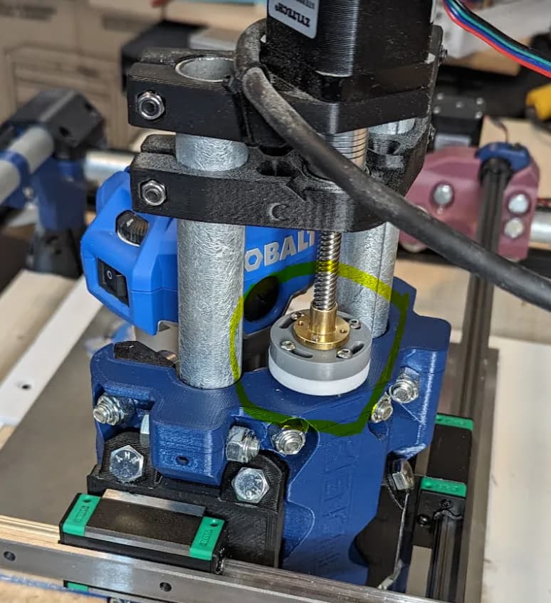
I would think the bearing spinning means it’s no longer in contact with the z-rail and undergoes rotation via vibrations from the router.
This may mean the fitting on the system is loose or gets loose when under the work strain.
I am undecided about that bearing. Clearly it would benefit from some tightening, but after seeing the rest of the video, it seems like there’s not much relative motion between the router and the core. But it’s not zero, either, and I could see how some looseness there could amplify vibrations.
Unfortunately I’m not near the machine for a few days, but when I get back I will recheck bolt tension through the core, and I will also run a little test with a dial indicator to see how much the rail deflects under 10 lbs vs the original steel conduit. My original assumption was the rail would be much stronger than the conduit, but my new theory is that it’s not. If stiffness appears to the be the issue, I might try clamping some 2020 extrusion along its length. Aluminum isn’t the stiffest, but it would at least change the resonant frequencies of the rail.
I was just checking my system this morning for machining aluminum and there was about 1/8" deflection at the bearing on the y axis. The core had 3 cracks there right next to it. I tightened it down and the only slop now is the z lead screw, which is more than I think it should be.
I tightened it down and the only slop now is the z lead screw, which is more than I think it should be.
In my initial build, my lead screw had and absurd amount of play/backlash, like 0.5-1.0mm. Maybe I used an old, already-worn leadscrew and nut, but they’re all going to have some backlash.
Basically you attach each printed parts to a TR8 nut, and then tighten them together on the lead screw until they bind completely. Then use four bolts to compress the two printed parts together to release just enough tension to allow the leadscrew to move. It’s effectively the same as the anti-backlash things with a spring, but those are typically for low load – this is basically the same thing but with a much stiffer spring (the two plastic parts compressed).