Primo CNC
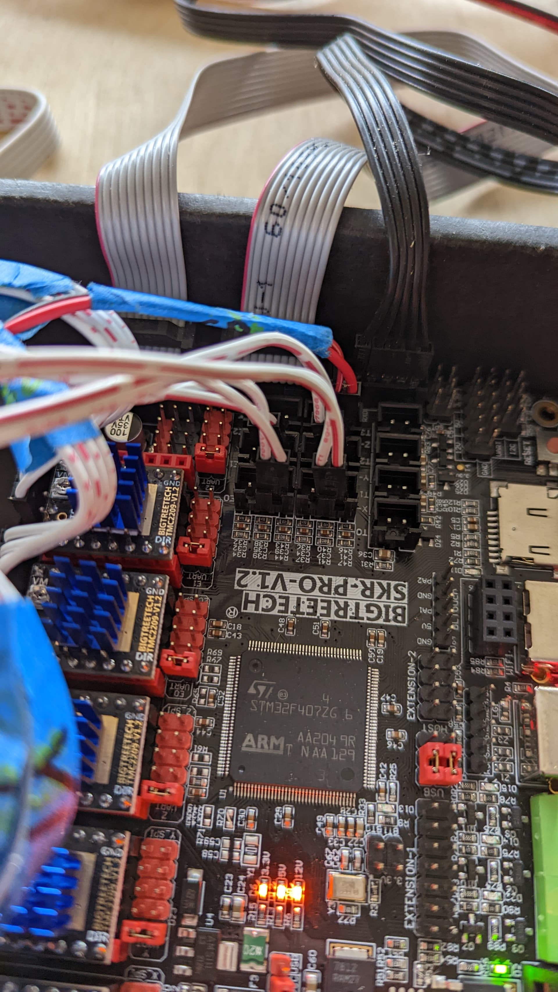
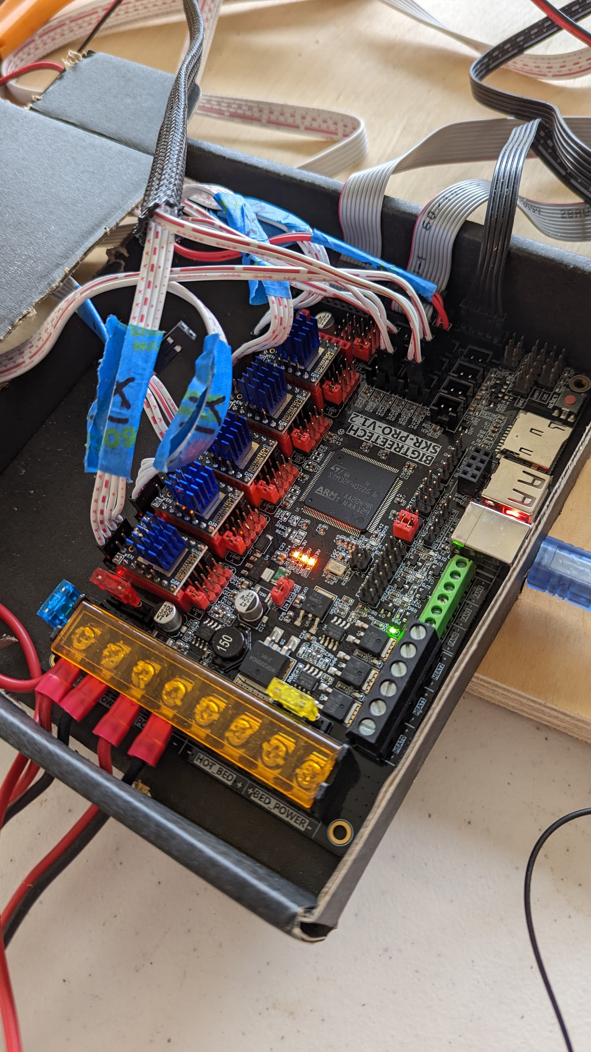
SKR-Pro-V1.2
BIGTREE_TFT35_V3.0_E3.27.x.bin
V1CNC_SkrPro_Dual_2209-2.0.9.2
Repetier Host
I have finally built my Primo. It is still a mess electrically, but everything is plugged in and the x, y, and z axis move when promted in Repetier Host. However, when I run command M119, it shows:
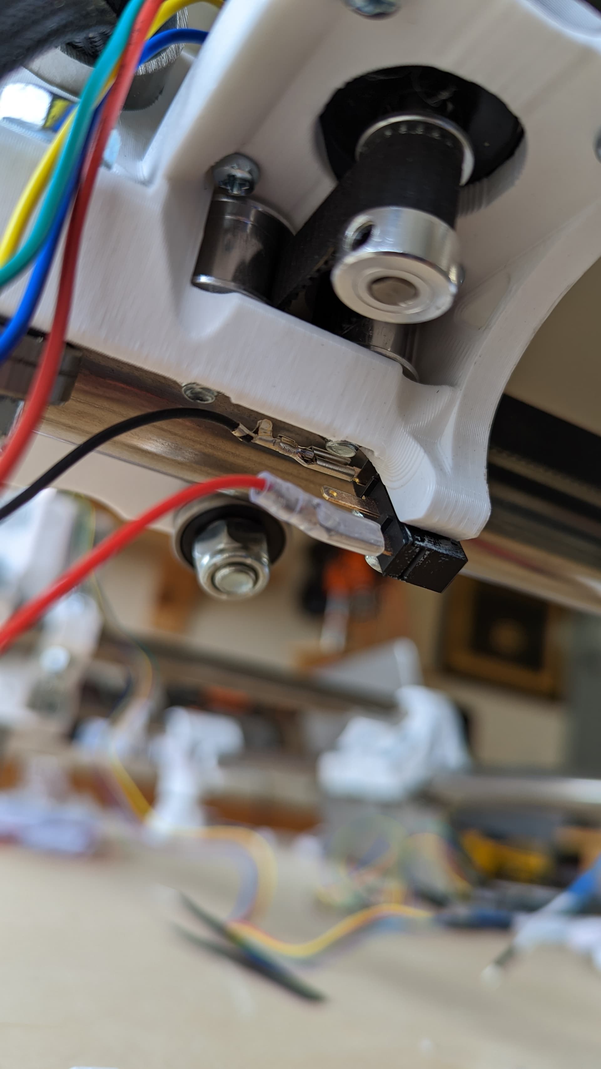
I can get z_min to TRIGGER by touching the wires together, but I cannot get it to stop the z-axis movement. Furthermore, I cannot get x, x2, y, or y2 to “open”. I have tried flipping wires. I even tried manually touching two wires together. They are always showing triggered.
Just tried. Still “triggered”. I can plug it just the black/red wire to the board and it will show “triggered” regardless of if I have the other end of the wires touching or not.
As John indicated, in your original picture I don’t believe the switch is wired normally closed. Step 1 is to repeat your experiment above with a shorted endstop and be absolutely sure the issue is the board and not something related to your wiring. You want to be careful when you short ‘s’ and ‘-’ since shorting ‘+’ to ground can damage a board. Take your current wiring out of the test by using some other wiring or method to connect the ‘-’ and the ‘s’ pins. Assuming directly shorting still indicates ‘Triggered,’ read on.
We have found on the forum that there are some SKR Pro boards that have issues with endstops. It is a hardware problem related to, in my opinion, a poor design probably combined with some out of spec components. If your board is one of the bad boards, you have the following choices:
Get a replacement board
Disconnect the endstop LEDs
Add a pullup resistor between the ‘s’ pin and the ‘+’ pin for each endstop.
Disconnecting the LEDs does require you to modify your board. Pullup resistors can be added without physically modifying the SKR Pro. In the limited number of posts I’ve seen on the forum, both solutions worked in all cases.
Okay, so I now can get the switch to cycle between “triggered” and “open”. My understanding is that we want the switch to be normally “triggered” and so when the switch is not pressed I should read “open” and when pressed it should read triggered, but also if a wire came loose it would also say “triggered” and not allow the CNC to operate. This is a fail safe. In order to have my switch read properly, I need the black and red wire connected to the outside pins with the middle pin of my limit switch not connected to anything. How wrong am I?
Next question, regardless of above answer:
I can now get M119 to say “triggered” or “open” by pressing the switch. But why isn’t this stopping my X-axis motor from moving in Repetier Host?
I need the black and red wire connected to the outside pins with the middle pin of my limit switch not connected to anything. How wrong am I?
I just checked, and my wiring matches yours. I thought I used the middle and far connections. But your machine should read ‘open’ on all four switches when the switches are not pressed. If they read ‘triggered,’ then the normally closed connection is not being completed, so bad switches, bad wiring, bad board, or bad firmware settings.
I can now get M119 to say “triggered” or “open” by pressing the switch. But why isn’t this stopping my X-axis motor from moving in Repetier Host?
Endstops switches are only sampled during homing. They are not used during other operations. If your machine is homed, Marlin will prevent you from moving to negative absolute positions. This is a “soft stop” and does not use the switches. Note that most of us use a G92 to reset the origin for doing jobs. The G92 clears the ‘homed’ state, so soft stops are not available during cutting.
Looking closely at the switches, each terminal should be labeled. The three terminals are most commonly called NC (for “normally closed”), NO (for “normally open”) and COM (for “Common”). The V1 firmware expects that you will use the NC and COM terminals, otherwise known as “using normally closed switches” or “wiring them as NC.”
In my experience, you can’t count on placement of the terminals, you need to find the markings, or check the switch with a continuity tester or multimeter.
The Normally Closed terminal has continuity with Common when the switch is at rest, and loses continuity when activated.
The Normally Open terminal has no continuity with Common when the switch is at rest, and gains continuity when activated.
There should be no connection at any time between the NO and NC terminals.
If you had originally used the NO and NC terminals, that would explain why the state of the connection didn’t change when activating the switch, and why they always showed “Triggered.” The board was expecting to see a completed circuit, but you had an open circuit, even when the switch lever was pressed.