I have all the stuff I need from V1 plus the Jackpot2 controller. I am about to build the MPCNC Primo and have read through the build instructions from top to bottom. They look great until I get to the electrical part. How do I hook up the controller to the stepper motors and limit switches? I see partial information under the section on Jackpot2. After some head scratching I think I can figure out how to hook up the stepper drivers. I am not at all sure about the limit switches. This is my second cnc router build. The first was a Mill Right kit and they explained were each wire went - from what to what. We really need this for the MPCNC and I am willing to write this up and contribute it to the build pages if someone will give me this information.
Greetings , shopmad and welcome to the V1 community forums.
Really cool that you’re willing to help with documentation. I’m tagging @jeffeb3 or @vicious1 as we need to move this topic to either a jackpot section or MPCNC section of the forum. The education section is for educators or other interested parties looking to use or enable V1 machines or controllers in educational environments.
We won’t let that stop us though.
For the stepper motors, wiring is exactly as with jackpot v1 or V3.
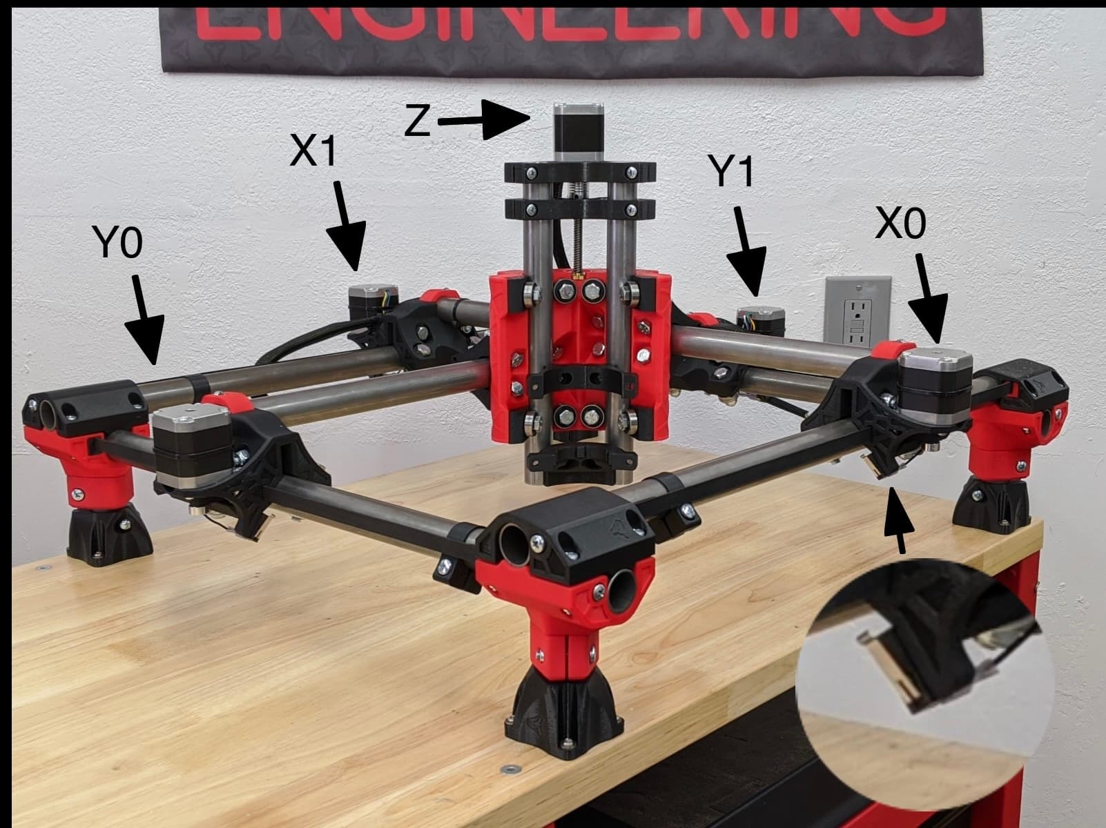
So, for MPCNC the order as you go across the board is = X0, Y0, Z, X1(A), Y1(B).* In other words your X1 motor gets plugged into the driver output labeled A and so on.*
I’m replying from mobile so will be editing several times to add more.
Edit 1:
There’s a note here on the jackpot V2 page with a caution, essentially that jackpot V2 was a work in progress and that’s why they’re available at such a discounted price:
https://www.v1e.com/products/the-jackpot2-cnc-controller
DANGER!!! Please Read
These are missing PWM capabilities on the 3 outputs. If you are looking to update a previous V1 board and are not using a laser, this is a great way to get an inexpensive new controller.
Not for the newbie!
I have multiple jackpot V2 boards and except for laser they work great.
Edit2:
The endstops plug into the connectors in the bottom right corner of the jackpot V2, here:
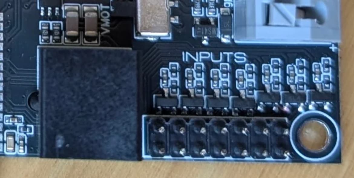
There is auto-squaring on X and Y axis, so you hook up the endstops as defined in the config.yaml .
I’ll need to go look at the configuration file to check it as I only have LowRiders and lasers running jackpot.
Edit 3:
The Jackpot V2 files on github are here:
That includes the config.yaml file.
Below are some excerpts from that file that instruct us how to hook things up:
    #X
    motor0:
      limit_neg_pin: gpio.25:high
So, this means the endstop for motor X0 should plug into GPIO.25 on your Jackpot V2.
   #A
    motor1:
      limit_neg_pin: gpio.35:high
The section above means the endstop for motor X1 plugs into GPIO.35 on your Jackpot V2.
    #Y
    motor0:
      limit_neg_pin: gpio.33:high
Motor Y0 endstop plugs into GPIO.33
     #B
    motor1:
      limit_neg_pin: gpio.34:high
Motor Y1 endstop plugs into GPIO.34.
For the Z axis, if you have the Z endstop installed at max travel up, the config says it plugs in to:
   motor0:
      limit_neg_pin: NO_PIN
      limit_pos_pin: gpio.32:high
GPIO.32
And last, if you use a touch probe:
probe:
  pin: gpio.36:low
  toolsetter_pin: NO_PIN
  check_mode_start: true
That would plug in to GPIO.36.
Hopefully some of our MPCNC users in the community will look my reply over and point out anything I messed up.
Edit 4: Here’s the detail from the schematic, to show the order of the GPIOs:
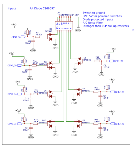
So, across the header it is:
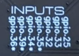
GIPIOs 36,39,34,35,32,33,25.
Which is what this legend means on the board:
Thanks for the quick reply, MakerJim.
Yes, I misunderstood what Education meant. Feel free to move this discussion to the appropriate section.
The GPIO information is very helpful. Are the stop switches wired as normally open or closed? I saw the driver information before and figured that out. I also saw the warning about not being able to use a laser with Jackpot2 but I’m not planning on using one.
I will document and photograph the electronics part of my build and offer it for the build site. It may take a while as today I was building a rolling base for the CNC so I have a way to go. I have, however, already printed all the 3d parts and have bought the steel tubing.
I think the instructions should have a way to check out the wiring before final assembly. I wonder if one can do damage the belts are in place and the steppers work against one another.
The V2 is not getting a rerun, so not really necessary.
Not really, if you don’t start driving it around full speed. If you move it slowly you will immediately notice.
Closed. The endstop switches break the connection when pressed. If the wire breaks, the endstop triggers.
Necessary, no. But completely worhwhile. If we have a supported machine / controller type, we should document it. A jackpot V2 is a completely viable upgrade for an MPCNC that has an older controller- so I’ll bet others will benefit.
Yep, We use and strongly prefer NC endstop wiring. Users can deviate as you have full control over your build. It’s just not a good idea ![]()
Great. I think I have all the information I need for the build. I will add the note about moving the steppers just a little as a test.
Well I decided to change the documentation before building the machine. I just want to insert a photo and table showing the stop switch connection to gpio. I did not change any existing text – I just refer to it. But my grasp of Github is limited. I made the changes and created a branch (ptynan/V1EngineeringInc.docs) and put in a pull request. But I could not put my one image in the image folder for jackpot2. Github said I was not authorized.
looks good.
Thanks, hopefully the web/github master will make the change or tell me how to do it.