MP3DP V4 Build

Hey @Jonathjon, hope sensor mount works out for you, the slot/channel is my attempt at a guide and strain relief for the sensor wire. Hope the close up pics help at on MP3DP v4 - Aza's build - #224 by azab2c

1 Like

Yes sir! Huge help! Thank you!!!

Got it back on there with the wire behind it. great idea!!

1 Like

Nice! Noticed wiring connector on bottom of these sensors moves side to side slightly as filament is inserted/removed. So I ensure looped wire has enough slack to not yank on the connector.

1 Like

Will do! Thanks for the tip!!

Made a little progress today. Ended up moving a few things around. Now all of the power stuff will be on the right side panel. Hopefully it turns out well when done lol

1 Like

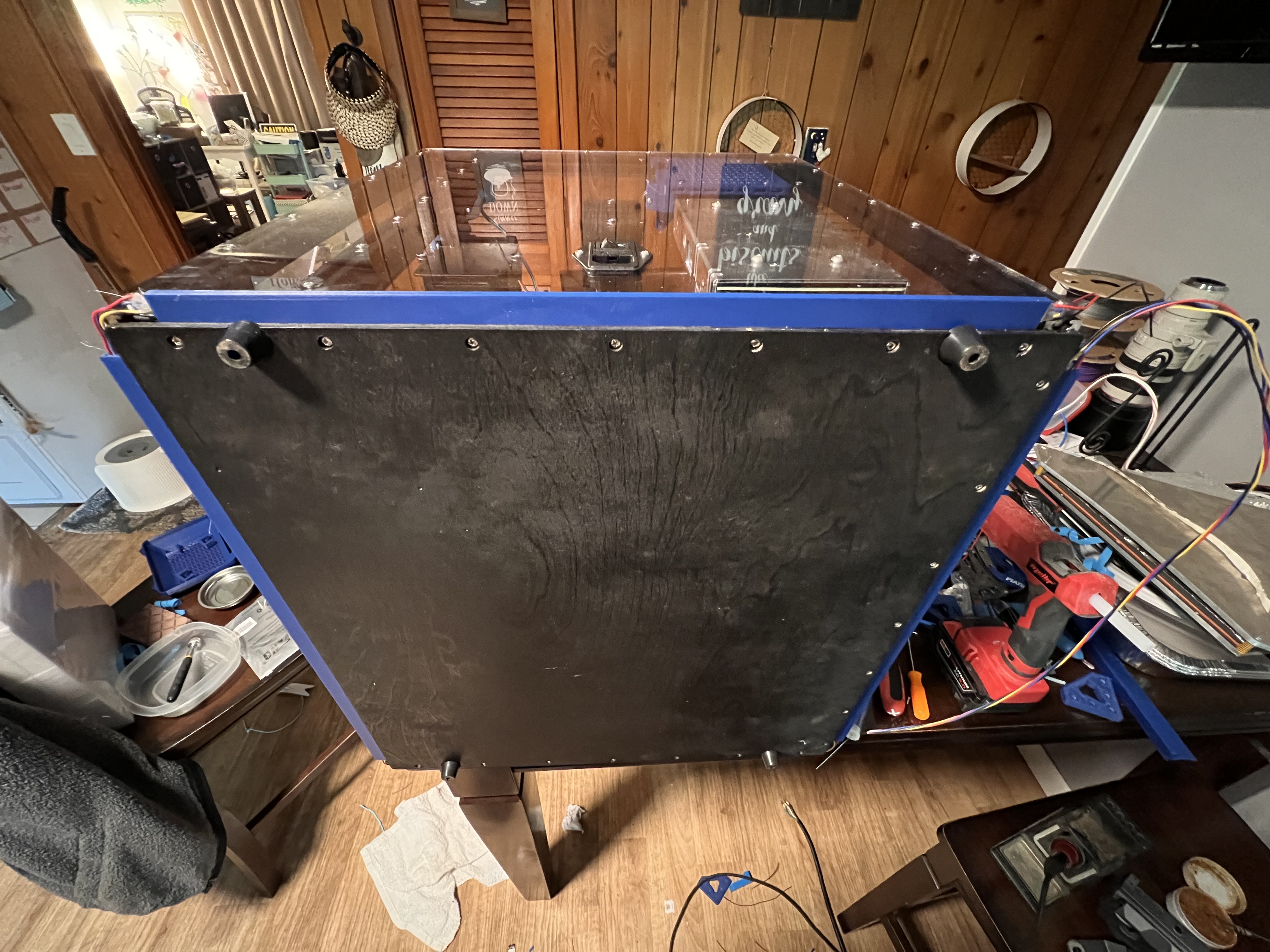
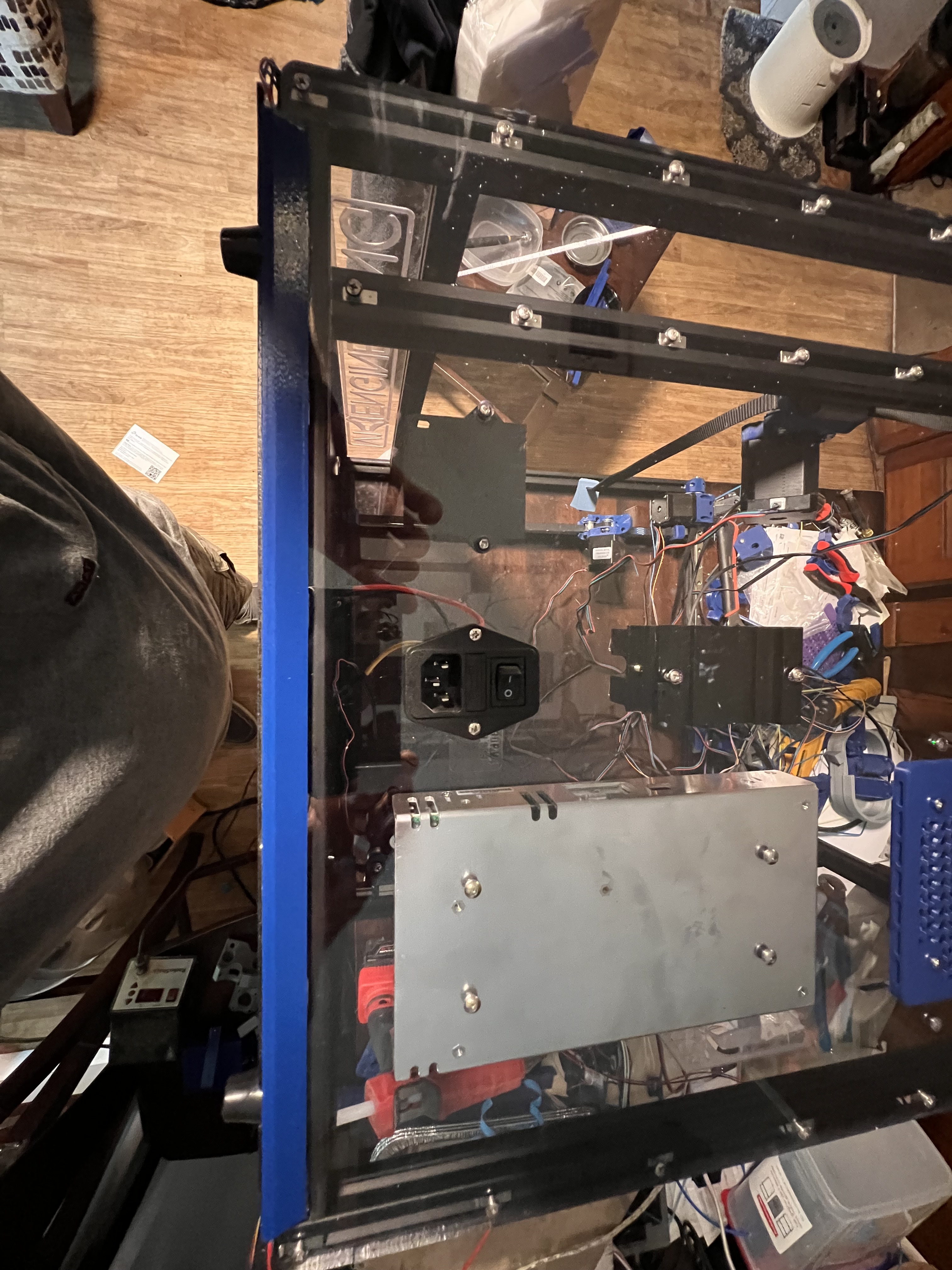
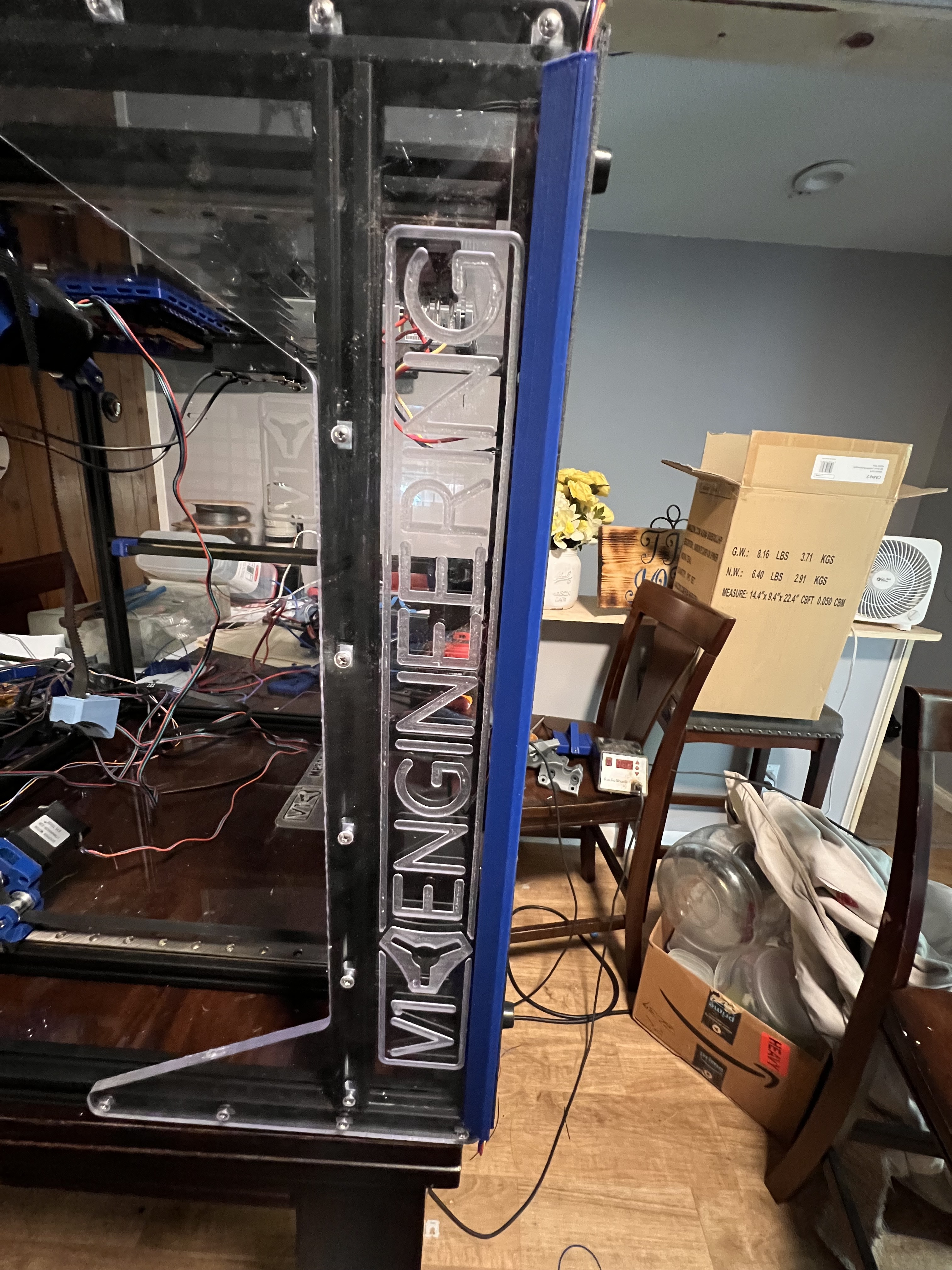
Finally got all my panels installed and the LEDs ran under them. Hoping that just lighting from the bottom will be enough. If not I’ll have to figure out a good way to run more across the top. Also have to see if I can draw up some corner pieces that will cover the wires up and not look stupid lol

3 Likes

Looks good. I’m looking forward to seeing the lighting in place.

2 Likes

Me too - I don’t even care if it doesn’t print! :smiley:

1 Like

Have a little more faith than that LOL. I sure hope it prints and prints well after all this LOL

Waiting on some ball bearing for the linear rails to come in today. One slid off more than it should have a dropped a “few” balls. Was able to find 2 but I’m pretty sure I heard at least 3 hit the floor. In my inexperience I never cleaned these when I built it originally. Going to take them apart and clean them REALLY good and then lube up with some Super Lube. Hopefully they will be in tip top shape after that. If all goes well I’m hoping to be at least starting rewiring everything this evening. All depends on how many distractions and pull a way’s happen LOL.

FYI if you are going to clean your linear bearings and lube with super lube there is a difference…

Bad superlube…

Good superlube…

I thought I could use the same stuff we use for lead screw. Boy was I wrong. Bearings wouldn’t hardly move. And of course I did 2 of them. First one I wasn’t sure if it was the balls were the wrong size just slightly or what. Second bearing was moving good before I started. That when I figured out it was the grease. Got them apart again and soaking in IPA/water. Hopefully it will go smoother this time lol

2 Likes

Wouldn’t move with the other stuff either. IDK how but the bearings are just too big. I cant see a difference in them and no easy way to measure. Cleaned all the old ones up and put them back and all is good now lol

These are the replacements I ordered
https://www.amazon.com/dp/B07YFVQ2Z4?ref=ppx_yo2ov_dt_b_product_details&th=1

Precision made, all in the wrong size…

Finally back to piddling with this thing. Trying to get it all wired up and running again. Much needed distraction currently.

@azab2c where did you hook up your smart filament sensor on the SKR? Shoot now that I think about it I’m not sure you are running the same SKR Pro 1.2 that I am.

From what I can find online I’m guessing it hooks to E0 Stop but I will need to double check that in the firmware.

Edit:

Does this look right? Trying to set it up to use E0 Endstop

This is how it comes in Marlin, But if I’m understanding it right I have to add the line for the pin:

#define FIL_RUNOUT#_PIN PE15

Am I understanding this correctly?

Yeah, you’re right my MP3DP uses Octopus v1.1 and I used Klipper as well. So, am not sure what Marlin changes would be needed. However…

ME: What Marlin firmware configuration changes are needed to use BigTreeTech Smart Filament Sensor?

ChatGPT 3.5:
Configuring the Marlin firmware to use the BigTreeTech Smart Filament Sensor involves several steps. Please note that the exact configuration may vary depending on the specific version of Marlin and the features supported by your 3D printer. Always refer to the Marlin documentation and the documentation provided by BigTreeTech for the most up-to-date information. As of my last knowledge update in September 2021, here are the general steps to configure Marlin for the BigTreeTech Smart Filament Sensor:

  1. Enable the Filament Sensor Feature:

    In your Marlin firmware configuration files (usually Configuration.h and Configuration_adv.h), locate the section related to filament sensors and uncomment the appropriate lines. Look for lines like:

    #define FILAMENT_SENSOR
    // #define FILAMENT_RUNOUT_SENSOR
    

    Uncomment #define FILAMENT_SENSOR to enable the filament sensor feature. If you want to enable filament runout detection as well, uncomment #define FILAMENT_RUNOUT_SENSOR.

  2. Select the Filament Sensor Type:

    BigTreeTech Smart Filament Sensor uses an optical sensor. In your configuration files, find the section that allows you to select the type of filament sensor:

    #define FILAMENT_SENSOR_TYPE 1
    

    Set FILAMENT_SENSOR_TYPE to 1 for optical sensors.

  3. Set the Pin Configuration:

    Specify the pins that the filament sensor is connected to:

    #define FILAMENT_SENSOR_PIN 2
    

    Replace 2 with the actual pin number to which your Smart Filament Sensor is connected.

  4. Set the Inverted Logic (if needed):

    Depending on the sensor and its wiring, you may need to invert the logic. In most cases, the default setting is not inverted (LOW when filament is present). If your sensor behaves differently, you can change it like this:

    #define FILAMENT_SENSOR_INVERT false
    

    Set FILAMENT_SENSOR_INVERT to true if your sensor is normally HIGH when filament is present.

  5. Configure Sensing Parameters:

    You can adjust the sensitivity and debounce settings to suit your filament sensor’s behavior:

    #define FILAMENT_SENSOR_DEBOUNCE 100
    #define FILAMENT_SENSOR_THRESHOLD 10
    
    • FILAMENT_SENSOR_DEBOUNCE sets the debounce time in milliseconds.
    • FILAMENT_SENSOR_THRESHOLD adjusts the trigger threshold for filament detection. You may need to experiment with this value to get reliable detection.
  6. Compile and Upload:

    After making these changes, compile the Marlin firmware and upload it to your 3D printer’s control board.

  7. Calibrate and Test:

    Once the firmware is uploaded, you may need to calibrate the filament sensor by following the manufacturer’s instructions. Test the sensor by manually triggering it with a piece of filament and ensuring it pauses or resumes printing as expected.

Remember that firmware and hardware compatibility can change, so always refer to the documentation provided with your specific hardware and the Marlin documentation for the version you are using. Also, make sure to back up your existing firmware configuration before making any changes to easily revert to your previous settings if needed.

ME: No idea if ChatGPT 3.5 is right. ChatGPT 4.0 is probably better. It’s sure convincing though🤯

That’s pretty much everything I found doing a google search. So we will see if I got it right or not lol. Working on finishing up the wiring now. man what a mess. This is really making me want to go CAN bus like you did. I need to do some more research on it and see if I can figure it all out. This mess of wires going to the hot end would be SO MUCH NICER if it was just a single 4 wire and done lol

Am really close to being able to share walk through that covers CAN Bus if that helps. Includes some issues I ran into and overcame as well. Will share when done.

1 Like

One thing that can be noted in ChatGPT answers is it’s absolute confidence in its answer. It can be absolutely wrong, but will still state things with the certainty of fact, even if those answers are self contradictory. (Or prefaced with “consult the documentation first”)

1 Like

That would be AWESOME!!! Thanks!

One thing to be aware of… The marlin changes for the filament sensor only work if you’re printing from an SD card.

If you use octoprint to print like I do, then the filament sensor has to be set up to work through a gpio pin.

Supposidly there’s a way around that, but it looked complicated.

1 Like