MP3DP v4 - Aza's build

This is somewhat, a very interesting discussion…
For some reason, when setting up the klipper (printer.cfg), I can not tell klipper (with CAN bus) that my stepper motor is 256 microsteps, anything over 128 will stall the printer…
In the other hand… Every single sample config file has microstep set to 16.
Here is an example of a generic coreXY printer.cfg

# This file is an example config file for corexy (and also h-bot)
# style printers. One may copy and edit this file to configure a new
# corexy printer.

# DO NOT COPY THIS FILE WITHOUT CAREFULLY READING AND UPDATING IT
# FIRST. Incorrectly configured parameters may cause damage.

# See docs/Config_Reference.md for a description of parameters.

[stepper_x]
step_pin: PF0
dir_pin: PF1
enable_pin: !PD7
microsteps: 16
rotation_distance: 40
endstop_pin: ^PE5
position_endstop: 0
position_max: 200
homing_speed: 50

I’m running my printer.cfg with 128 microsteps, which is the max I able to run the printer at 100mm/s +
If I try 256 microsteps the printer stall and give me a communicating error.

[stepper_x]
step_pin: PE2
dir_pin: !PB4 #add ! to invert motor
enable_pin: !PC11
microsteps: 128 #was 16
rotation_distance: 32
full_steps_per_rotation: 200
endstop_pin: EBBCan: PB6 
position_endstop: 0
position_max: 300
homing_speed: 100

I’m guessing that the EBB CAN bus communication does not have enough bandwidth to control 256 microsteps (10000000) CAN bus speed, the default is 500000

2 Likes

Appreciate the discussion and info. Helpful to know, will lookout for CANBus communication bandwidth getting saturated, and checkout diff microstep values, am currently using 16 as well. I just used because that was in the template, mindlessly used as-is, for now… Left bunch of notes for things to follow up on and understand better. So many settings, lots to learn… But am already liking Klipper’s rich Macro support. Really nice and fast being able to tweak settings within seconds, without recompiling and deploying firmware. Able to iterate, experiment and tweak so much quicker.

Diagonals are skewed in latest crown attempt, dimension lengths were great though. Before fixing/tweaking skew, I’m guessing overall belt tension/aligning should be checked/verified to be good enough. Tried strumming the belts a few times, maybe they’re ok, am not experienced enough to know. Considered trying a cheap 10lb Belt Tension Gauge? For now though, am trying alternative approach, “end-to-end test” to verify if belt tension is good enough… Run the machine harder than normal, see if anything skips/stalls/breaks…

Klipper has Skew correction settings, so may use that as-well/instead of tweaking belt tension.

2 Likes

When Ryan says we use 1/256, that is only in the 2209. The interface to the tmc2209 is 1/16th, and the driver tries to predict in between and actually scales the motor in 1/256 steps (which is also a reason why they are quieter).

Maybe, but the protocol klipper uses sends commands like, speed up to 100mm/s over the next 0.2s, then travel for 10mm, then slow down to zero over 0.4s. That trapezoid protocol is independent of the number of microsteps.

3 Likes

The closer you have the bed pivot location correct the less tramming tries it has to do. Those positions should be where the bolts are that hold the plate to the z carriage.

3 Likes

Yup, sorry I should have been more clear, this is if you are using interpolation. The klipper docs have all sorts of cool info I have referred to a few times. TMC drivers - Klipper documentation

3 Likes

Just realized Octopus’s USB-A port can be used to power PI. Just don’t know if it should?

Don’t think that port is already needed for my setup, for example am not plugging SD Card reader into the Octopus’s USB-A since Klipper/Pi is orchestrating prints.

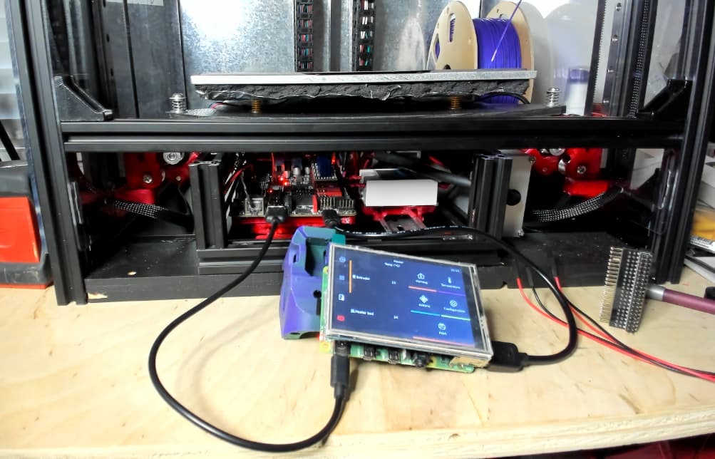
Was originally powering the PI via dupont wires between Octopus’s dedicated Raspberry Pi connector (J26), and the Raspberry PI VCC/GND pins on 20x2 GPIO connector. However, since the 3.5" TFT screen needs to connect to GPIO, in order to power Pi via GPIO, a GPIO splitter was needed (shown in the pic, discarded to the right). Looked at Octopus schematic, couldn’t see any electrically related pro/con connecting to USB-A vs J26?

Mounting a GPIO splitter worked, but made overall Pi + TFT assembly bulky. So am glad to be rid of that. However, I may end up reintroducing the splitter or similar if/when more of Pi’s GPIO needs to be connected.

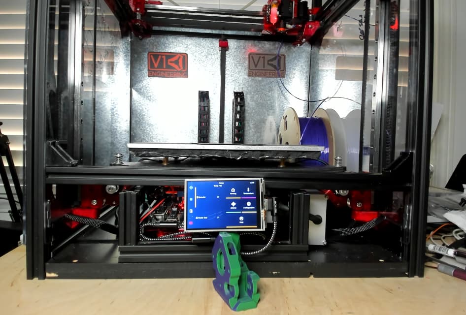
Current plan… Ordering some USB cables with right angled connectors. Hoping to make wiring compact enough to be smooshed into a functional but decent looking front mounted panel/enclosure.

btw - the screen currently feels like a gratuitous unrequired feature since klipper can be accessed via PC/Tablet/Phone. Adding anyway since all the cool kids seem to have one. Maybe I’ll understand the utility/value better after using for a bit.

Update: 1’ USB C to A cables with right angle connectors seem to work. Just need to make a more appropriate mount…

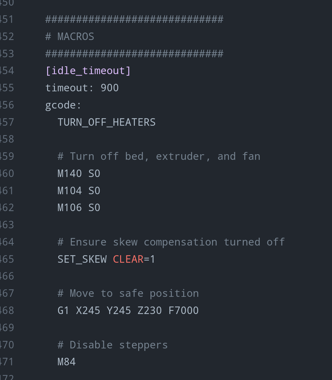
Am liking Klipper macros, for example can quickly configure a 15min idle timeout to safely park the bed just before motors are powered down. Without this, default behavior is for the bed to drop like a rock, unsettling, but doesn’t seem to break anything…

Still need to add separate macro to attempt safe park when config changes are saved, just before klipper resets, or maybe motors can be configured to hold position between reset (doubtful)?

5 Likes

I hadn’t really looked at J26 until now…

I had been using an external buck converter to convert 24V down to 5V for the Pi, but it looks like I can eliminate it. The main power input (not motor and not bed) for the Octopus has a step-down converter (SY8368A) to generate 5V for the board, which also goes to the USB-A and J26. Nice!

I have already cut up a USB cable to power the Pi from the buck converter, so I’ll probably just tap into J26 for power. I don’t trust the TX/RX on J26 though. The Pi might be spewing boot messages on power-up (I don’t know), and TX/RX could be susceptible to noise or have a lower max baud rate, so I’ll be sticking to USB for control. I don’t think it’s possible to communicate via the Octopus USB-A, or maybe it is possible but complicated, so the second USB connection is necessary.

Still a win for me to be able to ditch the external buck converter.

2 Likes

Someone made something like this already? What would you tweak/add?

Making front mounted (yet another…) Pi + 3.5 TFT case, because the Pi cases on Printables only meet 99% of my requirements. Several goals, like tidying things up and hiding messy wiring. Top will be red transparent PETG. Using clear ‘Transparent’ PETG for bottom part incase MK4 inspired running lights are added. Tempted to CNC acrylic to be a press fitted left panel, but already spent bunch of time on this. Notches in the bottom are for captured pivoting arms that’ll mount to 2020, at least that’s the theory…

4 Likes

Looks great! :slight_smile: Are you using Fusion 360?

2 Likes

Cheers! Yep, have been fighting with Fusion 360 on this longer than I’d like to admit :grinning:

Assembly, mount Core XY belts

Uploaded 5x sped up recording of me figuring out how to assemble the CoreXY belts. Slow playback to 0.25x if/when interested in understanding the audio of me ramble/explaining details. Audio isn’t great at 0.25x but may help with trickier steps.

The theme song for this post is “Yakety Sax”, open in separate tab while watching above video for maximum user experience.

Feedback/suggestions on better assembly sequence and techniques appreciated, cheers!

6/13 Update: Bought some discounted I2C to NeoPixel driver boards via Adafruit’s weekly 50% off stream, might use to help quickly setup power injected gratuitous lighting.

4 Likes

Yet another flipping Raspberry Pi Case…

Sized to fit my 3.5" TFT resistive touch screen that comes with 30x30x8mm fan. The fan is functional, but definitely louder than a Noctua.

Parts and print orientations…

Modeled case and 2020-mounts to enable easy tilting/removal for easy modding. Added some M5 hole knockouts for optionally attaching directly to 2020/something.

Works ok, hinge fit could be better. Expecting to mod/tweak further, but happy to share as-is if anyone wants to make one, cheers!

9 Likes

Klipper, 4 point z-tilt before heightmap calibrate

Video showing z-tilt and heightmap calibrate behavior for my build, at both room temp and 60C…

Configured z-tilt to probe 4 points with relatively loose 0.4mm tolerance, one near each corner. Overall Height map variance seems to be better for it than if I try 3 point Z tilt near the pivot points. Each point is probed twice, measured values usually match exactly, or are within 0.01mm of each other. Observing BLTouch values being consistent whether plate is room temp or been heated to 60C for 5+ minutes.

My printer.cfg Z homes at 50mm/s. Am using springs and steel washers on top and below springs. Alu bed uses wheel adjust springs, only because that’s what was on hand. Otherwise 'd have ordered/used regular springs. I’m using Mike’s ( @probrwr ) carriage adapter models/stls with my BIQU H2 V2S Revo. Appreciate Mike sharing those!

Am new to klipper, sharing what I’m doing to hopefully help Mike and others. But would appreciate guidance on what/how to change and do better. Cheers!

3 Likes

Panel Clips

Removed sheet metal back panel, was PITA when experimenting and making changes. Using removable panel instead, currently planning to use these clips unless someone suggests something else they’re very happy with…

https://github.com/SnakeOilXY/SnakeOil-XY/blob/master/BETA3_Standard_Release_STL/STLs/Panels/Top-panel/OPTIONAL_12x_mounter-inner-more-clearance.stl

Edit: Note the panel clips in github referenced above are for 1515 frame. Fortunately, the SnakeOilXY Dev recently shared a 2020 version via this SnakeOilXY Discord message.

2023-07-12: The 2020 model’s flexing arms are relatively short, causing overly stiff test print. So, have included modded version in my repo with gap edits and longer skinnier clip arms that flex more. My edits are not ideal, but they were fast to implement. The 2020 version I modified now has similar resistance/fit feel as the original 1515 model. Am printing PETG, with 0.6mm nozzle, 0.32mm layer height, Cura5+.

5 Likes

those clips are great, saved this for when my build gets going again.

1 Like

Created right-stepper-short-tab.stl, weaker than stock part, but hopefully good enough. Created to help enable a lid to rest along 2020’s outer 6mm.

Same print orientation as stock…

Edit: Added slotted tab holes that will work for builds with/without 1/16" internal panels…

image

1 Like

By the way, did you get more signatures at OpenSauce?

Nope, unfortunately I didn’t make time to pester YouTubers that have influenced/entertained/edutained me for their signatures. I didn’t even make time to watch some of the chat sessions they had, hoping to view some online.

Was very happy just spending a bulk of the time meeting and chatting with people that stopped by the V1 Engineering booth.

OpenSauce was tons of fun, so much to see, lots of interesting exhibits, and exhibitors to meet and chat with. Intending to visit again next year, will fly though.

4 Likes

Created/shared small simple MGN12 linear rail stop block on Printables and GitHub to help hold up build plate when tinkering. Recommend PETG or something with similar flex.

Am frequently accessing controller/components under the build plate. Also, holding the plate up can help when showing off your build… Was using zip ties, but frustration drove me to create these blocks that can (loosely) live in the 2020 channel when not in use.

5 Likes

Nice!

1 Like

That’s a great idea!

1 Like