MP3DP v4 - Aza's build

No more issues since you mentioned Mic6 is 0.381mm, cheers for that!

Am not fixing anything that needs fixing, am just tinkering and learning. Sorry for randomizing :slightly_smiling_face:

2 Likes

I think the best way to use the laser would be to turn off the leveling feature and just mark two equal points on the frame so there is no chance of the level actually being the issue.

It is the best idea yet, it is hard to measure something with no solid frame of reference.

1 Like

No no, glad to hear it.

Google/Youtube has been reading my mind/posts. They suggested I watch Steve (Voron Trident designer) calibrate a frame for one of his recent live build streams. Quite long, so here’s some related notes… In short, he measures diagonals, a lot.

This Stream is Part 2 of a series building a ZeroG Mercury One (https://docs.zerog.one). Upgrading an Ender 5 to CoreXY Printer, not from scratch build.

Stream starts ~1:30 talking about the frame being out of square > 2mm. Cause was “square” corner brackets not being truly square. Steve fixed by grinding them square. Steve’s assembling on project mat, on a flat slab of quartz.

4:00 Consider making an extrusion touch up station with disc sander, 123 square blocks and clamps. Requires time to build, align and squaring.
6:40 Ensure chopsaw trammed and squared if using one.
7:30 Use square corner brackets, but first you’ll probably need to square them, because… quality. Steve’s were < 90 deg
9:00 Start one side, sneak up on tightening into corners, switch back and forth.
12:00 Use 5mm blind joints to secure frame better
12:30 Tap holes for belt adjustments
20:00 Use soft feet to avoid base scratching.
31:30 Uses NOGA Deburring Kit
56:00 Mounting Y linear rails to top of extrusion.
1:02:00 Linear Rail spacers (offensively lime)
1:16:00 Quick view of Right XJoint (XY truck) in Fusion 360

Stream continues with assembling other parts, not frame squaring related afaik. I didn’t watch entire stream, just skipped around indexed sections.

3 Likes

little late to the party, but this is my favorite pic so far:

image

3 Likes

Added magnetic base and PEI. On reflection, adhering the magnetic base much earlier in the build would have been easier. People usually adhere the magnetic base before the heater bed, which is before the Alu Bed is mounted to the mdf/ply Bed Support Plate. Following that sequence would have made it easier to press roll the magnetic layer smooth.

However, on the other hand, the dumb luck stumbled upon alternative approach I took has helped me better understand how far off true flat my Alu bed is. So, upon further reflection, I don’t know what’s the best assembly sequence :man_shrugging:

Followed Wham Bam, and Steve Builds (Voron Trident designer) guidance for mounting magnet/heater base layers. Some notes:

3:41:00 Advice: Mount magnet layer to Alu plate before bed heater. Easier to roll flat.
3:42:00 Clean with Isopropyl liquid/wipes, remove debris, dust and oil.
3:45:00 Scrub with Scotch Brite Pad.
3:50:00 Set down and adhere magnet layer. Line up side and front, press down at back, check lined up, gradually peel back, press and “Roller Press” as you work towards front. Press it good, press it real good.
3:53:00 Cut holes in magnet layer.
3:55:00 Advice: Time permitting, let adhesive cure (Wham Bam docs reco 24-72hrs…). Putting under pressure and leaving to cure is good idea, that many people don’t follow.
3:57:00 Clean Alu plate for heater bed. Same as earlier, use Scotch Brite Pad .
4:03:00 Set down and adhere heater bed. Line up sides, similar to before, gradually peel and press down as you go, ideally with roller press.
-Heater bed went on slightly wonky, so, pay attention to multiple sides while adhering, don’t overly focus on just one edge.

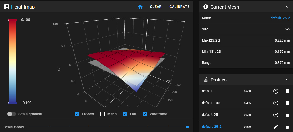
Adding PEI seems to have helped smooth out measured mesh heights a bit. Range 0.37mm seems pretty good, after you overcome the exaggerated perception that the visual diagram will impress upon you at first glance. Careful frame and/or Y linear rail tweaks maybe able to help improve further even.

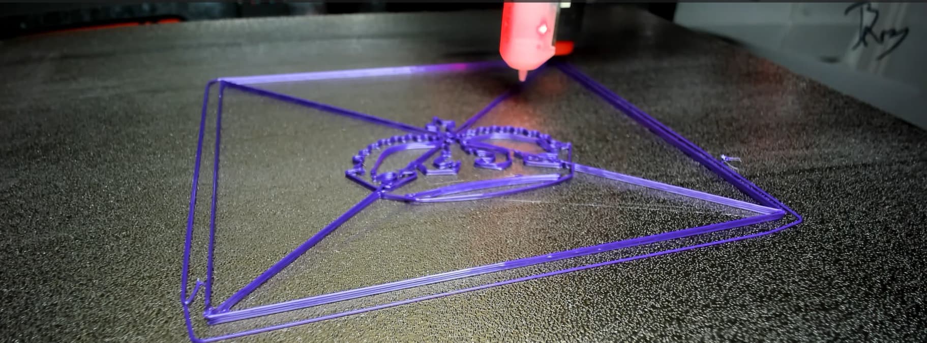
Using Bed Weld is helping my 100mm calibration crown stay put.

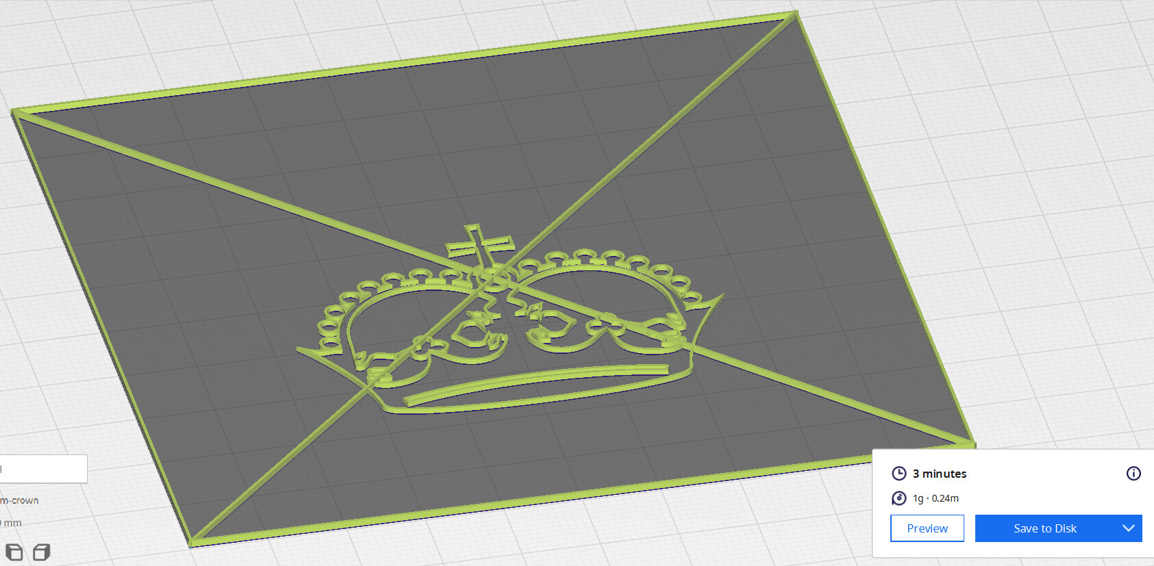
Currently printing bunch of 3min calibration crowns, nice fast try-tweak-repeat cycle time, tweaking various settings to try and dial in new Cura profile tuned for this printer. Am coming from a simpler Bowden Ender 3 Max. So, I get the opportunity to (re)learn settings for direct drive, linear advance, input shaping and bunch of other stuff that makes sense for this build. Will eventually share a Cura/Prusa slicer profile that works for me. Maybe someone has one already?

Update: Dimension lengths seem good, e.g. Crown’s outer border sides measured exactly 100mm. However, it’s skewed slightly, the diagonals were off (~140mm and ~142mm, should be 141.4mm). So, am following MP3DP v4 docs - Squaring and calibration, Klipper Docs - Skew Correction and other resources to fix…

3 Likes

That is a very flat bed and I love the cal crown.

3 Likes

I have a prusa profile, but I should look at it again. It isn’t my daily driver but I keep trying to switch. Trying to revamp things to use the ~50% nozzle/layer height ratio you pointed out, and keep my same flow rate so for a 0.5mm nozzle that means I chose 0.3mm @74mm/s instead of 0.37mm @60mm/s. Now I need to retune my accels.

Whole new test crown in the works, that is rad.

3 Likes

When I switched to my newest printer, I tried to just make the prusa mk3 profile work for my printer. They have some good presets and they move reasonably quick.

2 Likes

I’ve been trying to learn/use super slicer for mine. It seems to work well. But I have no idea if I have my profile set up truly correct or not lol

2 Likes

Any thoughts/opinions on using increments of 0.04 ? 0.04 magic number 3d printing - Google Search

Am blindly making sure everything, where possible, is divisble by 0.04. Widths, heights, distance, speed, acceleration, and nozzle widths even. No idea what’s the best practice, but pretty sure I’m over thinking it.

2 Likes

Our drivers are 256microsteps I don’t think that has any effect anymore, even when we used 16th stepping I never believed it.

2 Likes

The 0.04mm thing was based on 4 start lead screws. Definitely not a factor with a belt driven Z. The idea was that with a 4 start screw 200 full steps was 8mm travel, so 1 full step is 0.04mm. By making your Z layer heights full step increments, you supposedly get more consistency. This was based off of some comparison of commanded movement versus real world movement in microsteps where there is a real world error in microsteps that roughly follows a sine wave. So micro steps are just slightly off with a maximum deviation at 1/4 step. (IIRC Full step + 1/4 will be slightly more than commanded, full step + 3/4 will be slightly less.) But a full step from any microstep position will have a real world movement that is closest to the one commanded step of 0.04mm.

Well, that’s true, they are, but the actual amounts are so tiny in comparison to the bits of squirted plastic that they really don’t make enough difference in relation to the rest of a 3D printer mechanism.

Given that with 16x microstepping, the amount commanded is 0.0025mm, and the real world error is within a few percentage point of that, it’s really not a big deal.

If you want to be like that about it with the MP3DPv4 (or v3, for that matter) you will want your “magic number” to be 0.16mm, so layer heights of 0.16mm or 0.32mm.

4 Likes

This is somewhat, a very interesting discussion…
For some reason, when setting up the klipper (printer.cfg), I can not tell klipper (with CAN bus) that my stepper motor is 256 microsteps, anything over 128 will stall the printer…
In the other hand… Every single sample config file has microstep set to 16.
Here is an example of a generic coreXY printer.cfg

# This file is an example config file for corexy (and also h-bot)
# style printers. One may copy and edit this file to configure a new
# corexy printer.

# DO NOT COPY THIS FILE WITHOUT CAREFULLY READING AND UPDATING IT
# FIRST. Incorrectly configured parameters may cause damage.

# See docs/Config_Reference.md for a description of parameters.

[stepper_x]
step_pin: PF0
dir_pin: PF1
enable_pin: !PD7
microsteps: 16
rotation_distance: 40
endstop_pin: ^PE5
position_endstop: 0
position_max: 200
homing_speed: 50

I’m running my printer.cfg with 128 microsteps, which is the max I able to run the printer at 100mm/s +
If I try 256 microsteps the printer stall and give me a communicating error.

[stepper_x]
step_pin: PE2
dir_pin: !PB4 #add ! to invert motor
enable_pin: !PC11
microsteps: 128 #was 16
rotation_distance: 32
full_steps_per_rotation: 200
endstop_pin: EBBCan: PB6 
position_endstop: 0
position_max: 300
homing_speed: 100

I’m guessing that the EBB CAN bus communication does not have enough bandwidth to control 256 microsteps (10000000) CAN bus speed, the default is 500000

2 Likes

Appreciate the discussion and info. Helpful to know, will lookout for CANBus communication bandwidth getting saturated, and checkout diff microstep values, am currently using 16 as well. I just used because that was in the template, mindlessly used as-is, for now… Left bunch of notes for things to follow up on and understand better. So many settings, lots to learn… But am already liking Klipper’s rich Macro support. Really nice and fast being able to tweak settings within seconds, without recompiling and deploying firmware. Able to iterate, experiment and tweak so much quicker.

Diagonals are skewed in latest crown attempt, dimension lengths were great though. Before fixing/tweaking skew, I’m guessing overall belt tension/aligning should be checked/verified to be good enough. Tried strumming the belts a few times, maybe they’re ok, am not experienced enough to know. Considered trying a cheap 10lb Belt Tension Gauge? For now though, am trying alternative approach, “end-to-end test” to verify if belt tension is good enough… Run the machine harder than normal, see if anything skips/stalls/breaks…

Klipper has Skew correction settings, so may use that as-well/instead of tweaking belt tension.

2 Likes

When Ryan says we use 1/256, that is only in the 2209. The interface to the tmc2209 is 1/16th, and the driver tries to predict in between and actually scales the motor in 1/256 steps (which is also a reason why they are quieter).

Maybe, but the protocol klipper uses sends commands like, speed up to 100mm/s over the next 0.2s, then travel for 10mm, then slow down to zero over 0.4s. That trapezoid protocol is independent of the number of microsteps.

3 Likes

The closer you have the bed pivot location correct the less tramming tries it has to do. Those positions should be where the bolts are that hold the plate to the z carriage.

3 Likes

Yup, sorry I should have been more clear, this is if you are using interpolation. The klipper docs have all sorts of cool info I have referred to a few times. TMC drivers - Klipper documentation

3 Likes

Just realized Octopus’s USB-A port can be used to power PI. Just don’t know if it should?

Don’t think that port is already needed for my setup, for example am not plugging SD Card reader into the Octopus’s USB-A since Klipper/Pi is orchestrating prints.

Was originally powering the PI via dupont wires between Octopus’s dedicated Raspberry Pi connector (J26), and the Raspberry PI VCC/GND pins on 20x2 GPIO connector. However, since the 3.5" TFT screen needs to connect to GPIO, in order to power Pi via GPIO, a GPIO splitter was needed (shown in the pic, discarded to the right). Looked at Octopus schematic, couldn’t see any electrically related pro/con connecting to USB-A vs J26?

Mounting a GPIO splitter worked, but made overall Pi + TFT assembly bulky. So am glad to be rid of that. However, I may end up reintroducing the splitter or similar if/when more of Pi’s GPIO needs to be connected.

Current plan… Ordering some USB cables with right angled connectors. Hoping to make wiring compact enough to be smooshed into a functional but decent looking front mounted panel/enclosure.

btw - the screen currently feels like a gratuitous unrequired feature since klipper can be accessed via PC/Tablet/Phone. Adding anyway since all the cool kids seem to have one. Maybe I’ll understand the utility/value better after using for a bit.

Update: 1’ USB C to A cables with right angle connectors seem to work. Just need to make a more appropriate mount…

Am liking Klipper macros, for example can quickly configure a 15min idle timeout to safely park the bed just before motors are powered down. Without this, default behavior is for the bed to drop like a rock, unsettling, but doesn’t seem to break anything…

Still need to add separate macro to attempt safe park when config changes are saved, just before klipper resets, or maybe motors can be configured to hold position between reset (doubtful)?

5 Likes

I hadn’t really looked at J26 until now…

I had been using an external buck converter to convert 24V down to 5V for the Pi, but it looks like I can eliminate it. The main power input (not motor and not bed) for the Octopus has a step-down converter (SY8368A) to generate 5V for the board, which also goes to the USB-A and J26. Nice!

I have already cut up a USB cable to power the Pi from the buck converter, so I’ll probably just tap into J26 for power. I don’t trust the TX/RX on J26 though. The Pi might be spewing boot messages on power-up (I don’t know), and TX/RX could be susceptible to noise or have a lower max baud rate, so I’ll be sticking to USB for control. I don’t think it’s possible to communicate via the Octopus USB-A, or maybe it is possible but complicated, so the second USB connection is necessary.

Still a win for me to be able to ditch the external buck converter.

2 Likes