My printer uses mesh leveling (like many printers these days) and the Z is constantly changing up and down as XY changes. So I don’t buy that full step multiple stuff at all. The range in Z is well over 0.04mm and I get very consistent Z layers.
1 Like
I messed with the lead screws…took them out of the couplers and put them on a straight edge. One was ever so slight raised (not flat). I put it back to get leveled the x axis and this time I reprinted the tower cube.
I used super slicer - default settings for a voron 350 - 2 walls, 0 infill, 4/4 top and bottom… I am pretty sure me messing with the lead screws has zero impact. The tower test when doing the pressure advance was pretty clean too and that was before messing with the lead screws.
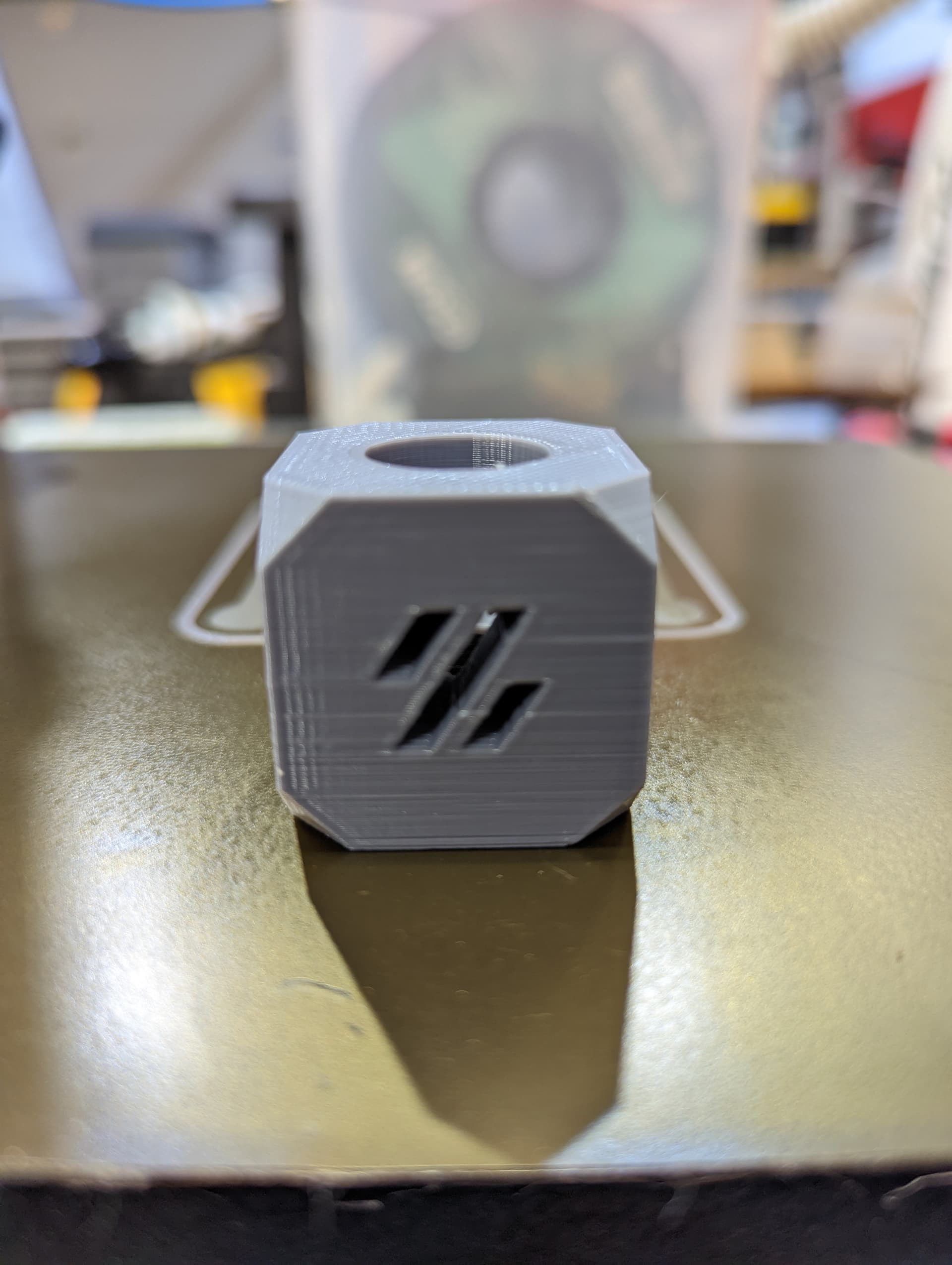
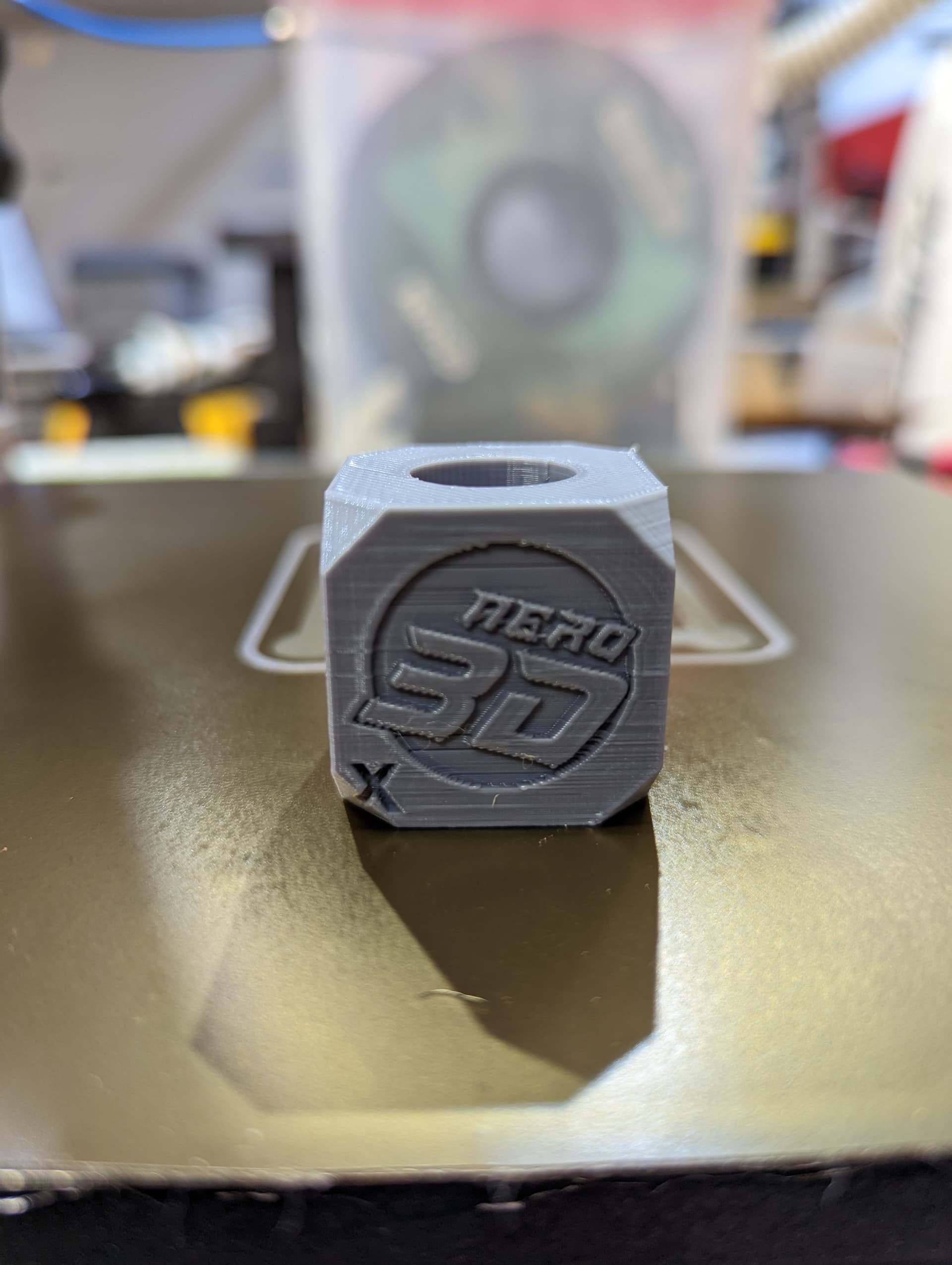
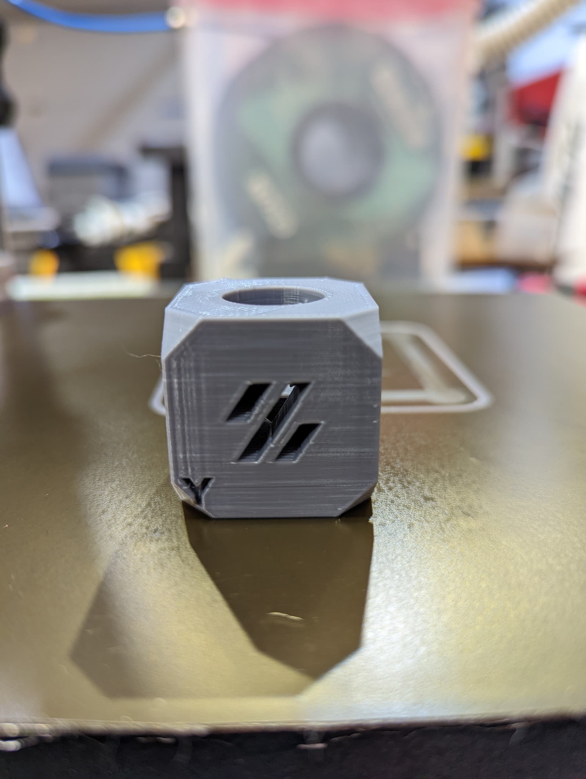
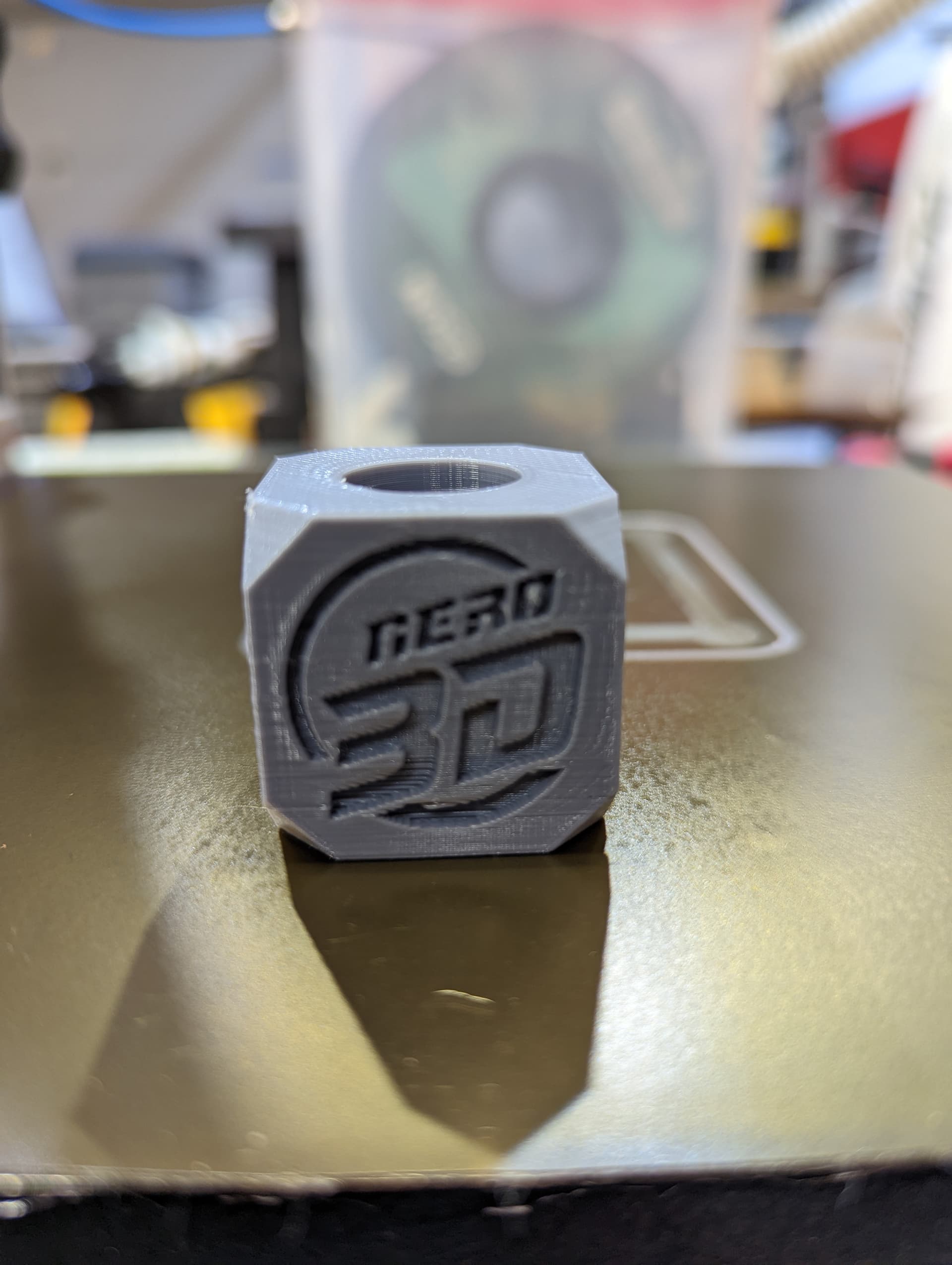
I was watching the Nero 3d live stream tonight and saw he had his own cube so I printed that on the inside of the tower. This print now looks like all of the other prints and nothing like the print quality on the tower cube. I am really not sure what is going on … if its mechanical or slicer related.
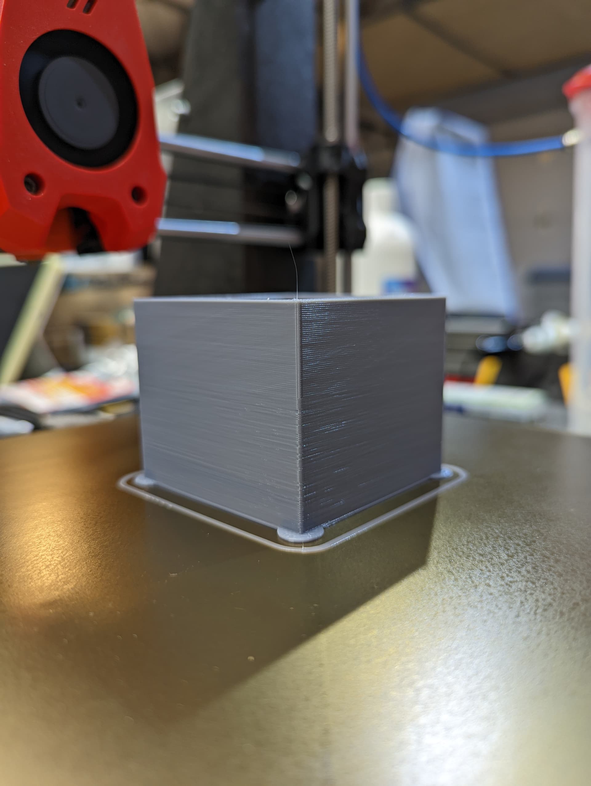
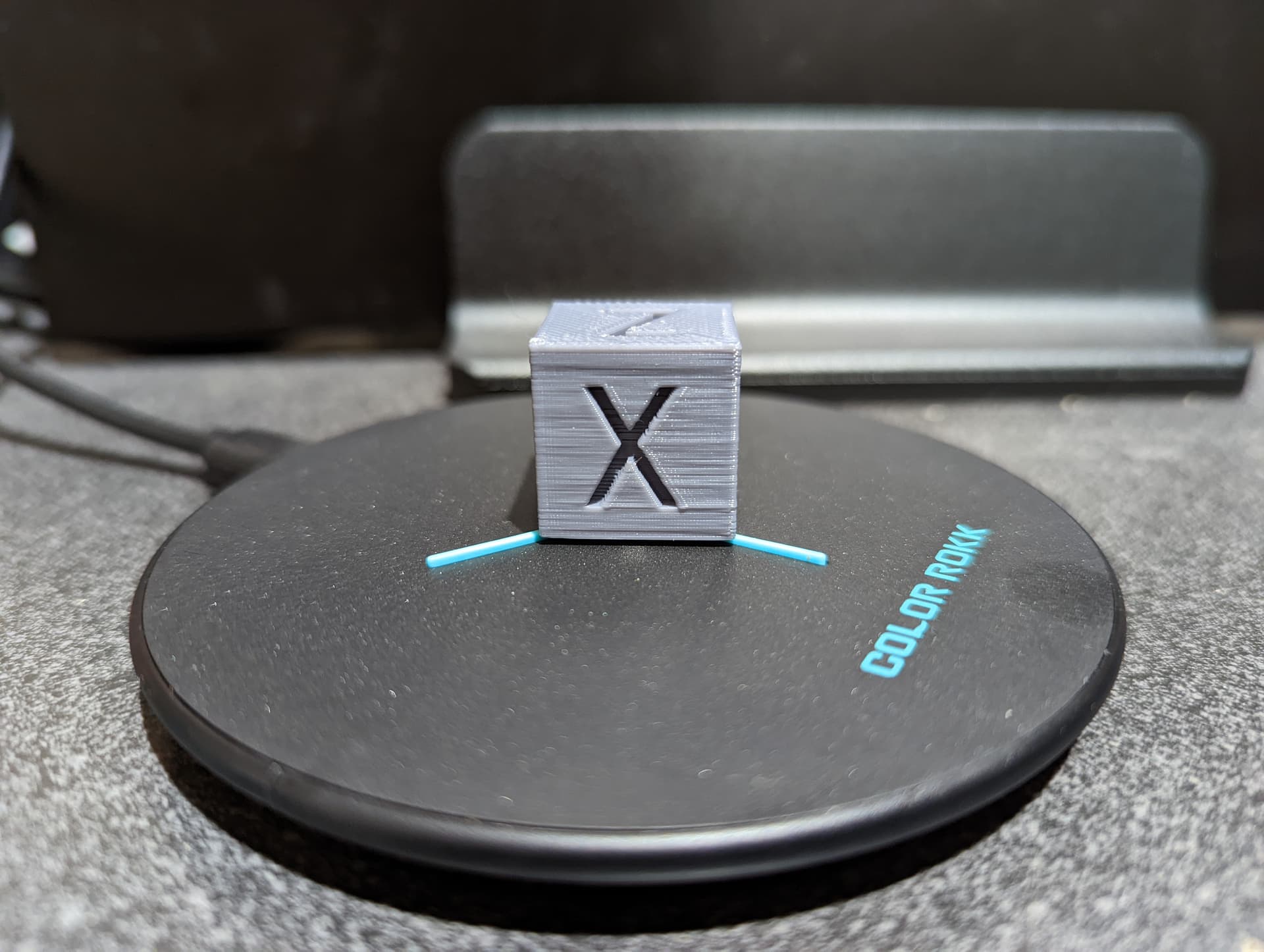
The lines on https://us2.dh-cdn.net/uploads/db5587/original/3X/8/1/81f109b1fd42a693eb90e7e8961ebdf6a4f44f47.jpeg look like what we call “the ripple”. It’s caused by all belt driven printers, but unless you have a really dialed in printer, the other print artifacts kinda conceal it.
You have some ringing around the corners, some resonance tuning should help with that.
The corners are also really wonky so the acceleration settings seem to far off for the resonance to help.
Have you walked through teaching tech tuning guide? It is really good.
https://teachingtechyt.github.io/calibration.html
At the minimum, I would do esteps and accel. Temp and retract are awesome as well.
I am in the process of going through all of that now… hind sight is 20/20 I know I should have started there but didn’t… so far the outcome looks good. I have done the PID tuning for hotend and bed. adjusted my rotation distance for my extruder. I have adjusted the belts to where they should be tension wise. I did a 20mm test cube and now I am working on the slicer flow calibration. Yesterday I also adjusted the Z stepper current. After I get the flow dialed in I am going to reprint the original “face” part as Jeffeb3 coined on one of my photo line ups.
1 Like
Pay attention to things like retract speed. If you ask too much it will just not retract, and act like it is over extruding. So I usually run through all the steps of the tuning once quickly, then go through a second time with much more detail. All his test parts are very fast prints.
The downside is They are meant for slow printers. I ran into issue that my printer could outrun the cooling on such small parts. So when I really wanted to dial it in I redid it all by hand with parts scaled 200%+.
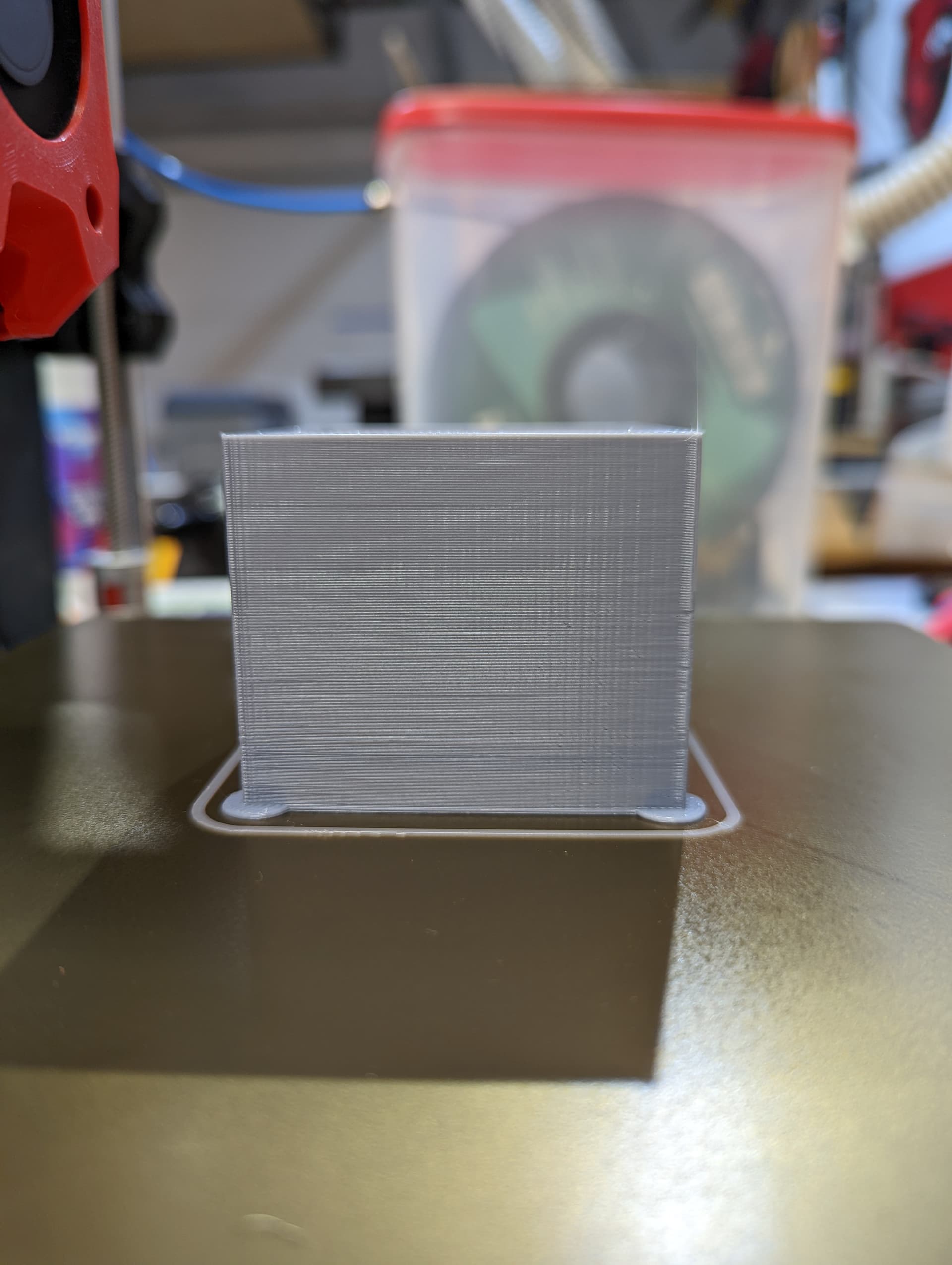
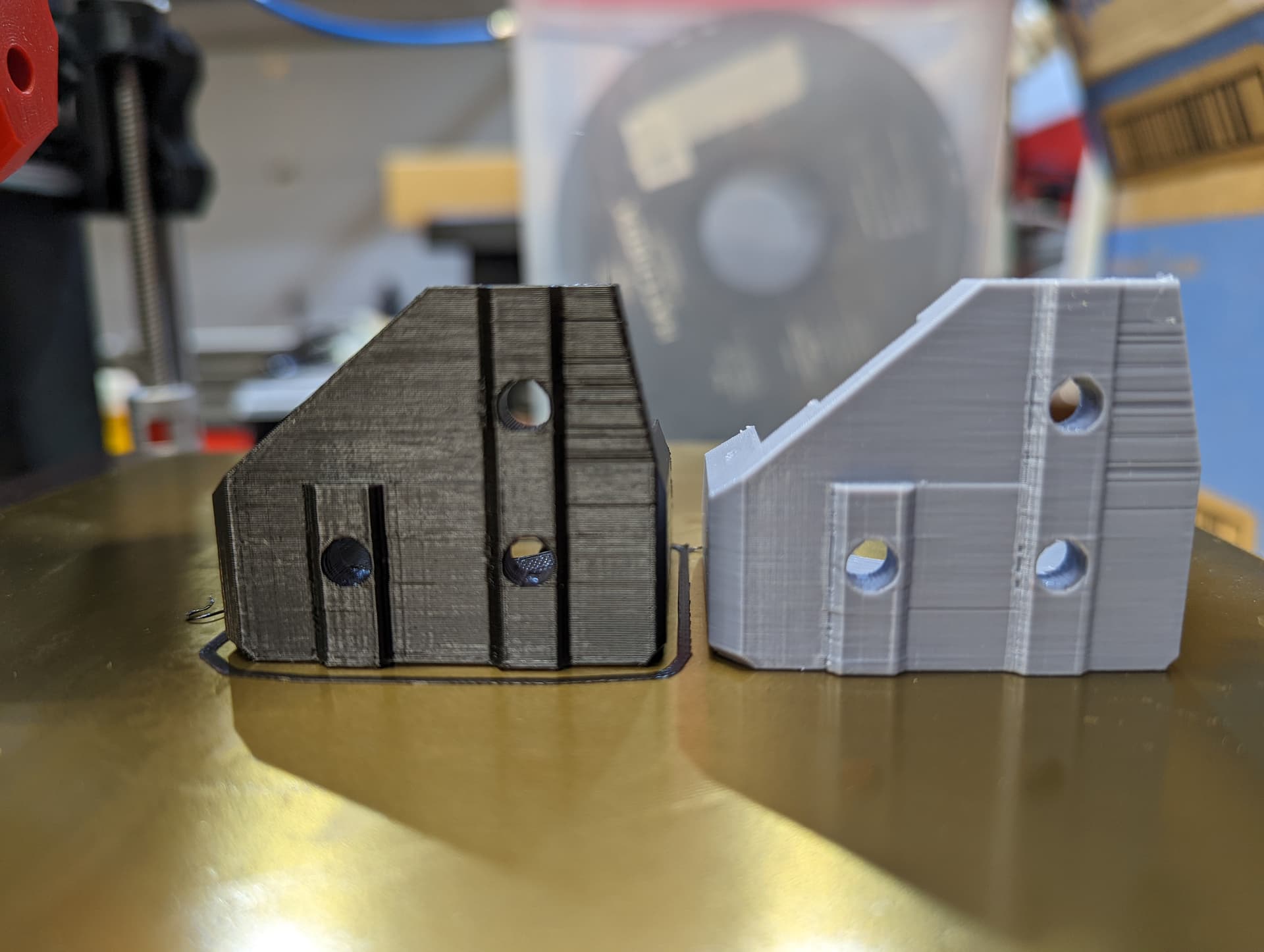
Part on far left is after initial tuning – camera surely brings out the lines but I would say the part is much better and looks better to the naked eye.
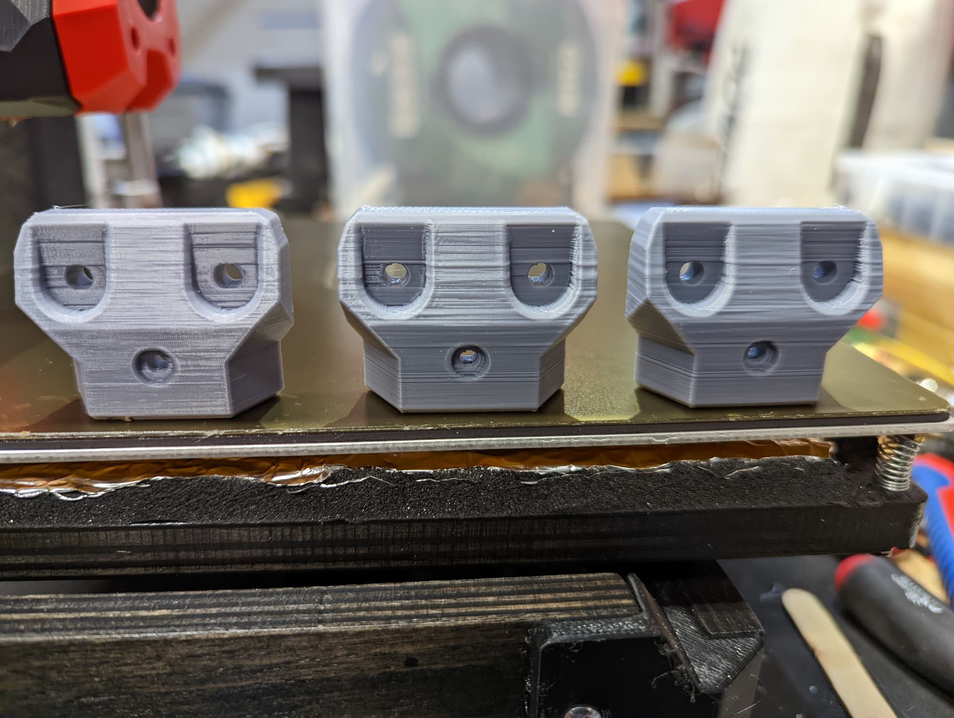
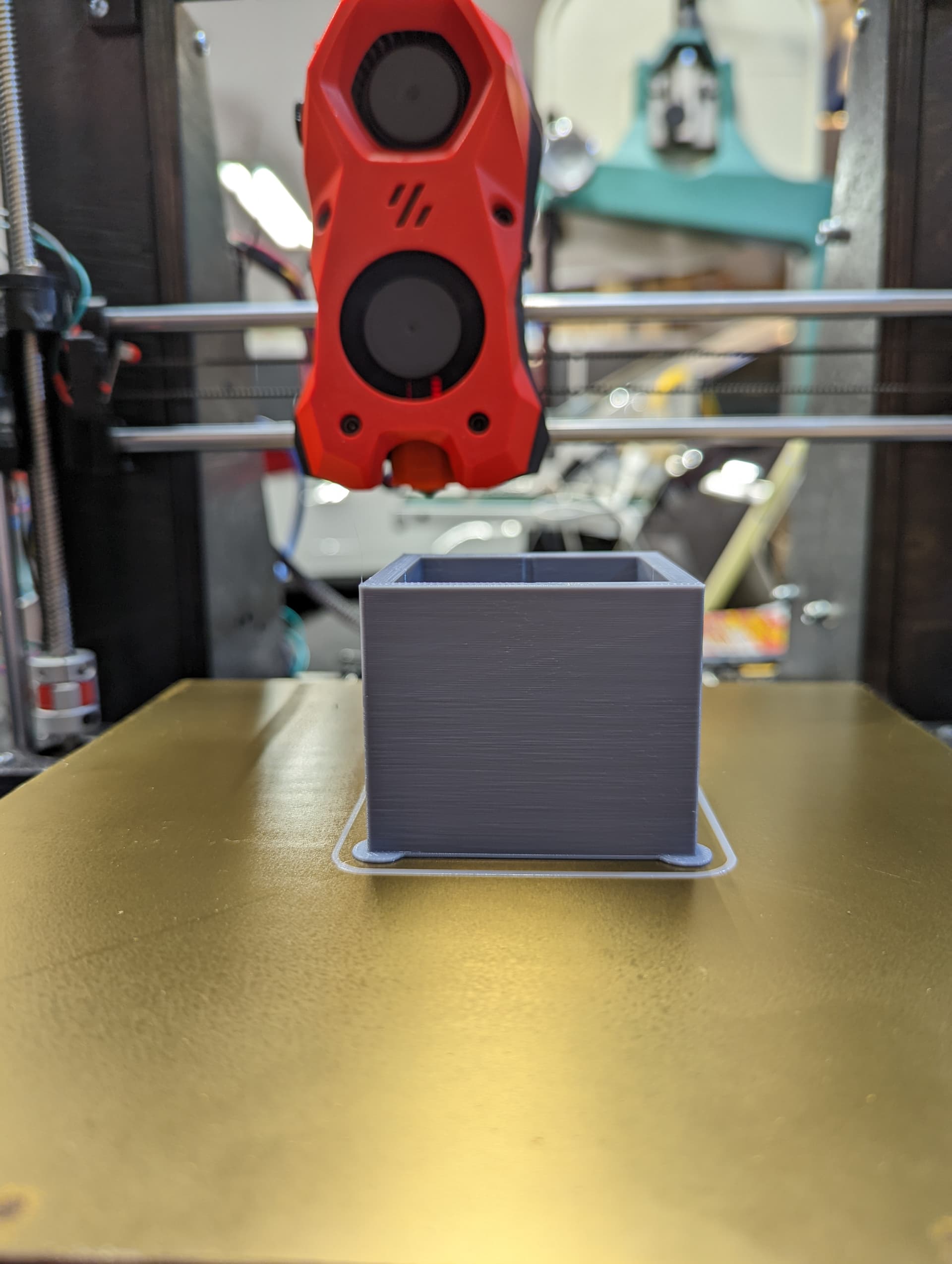
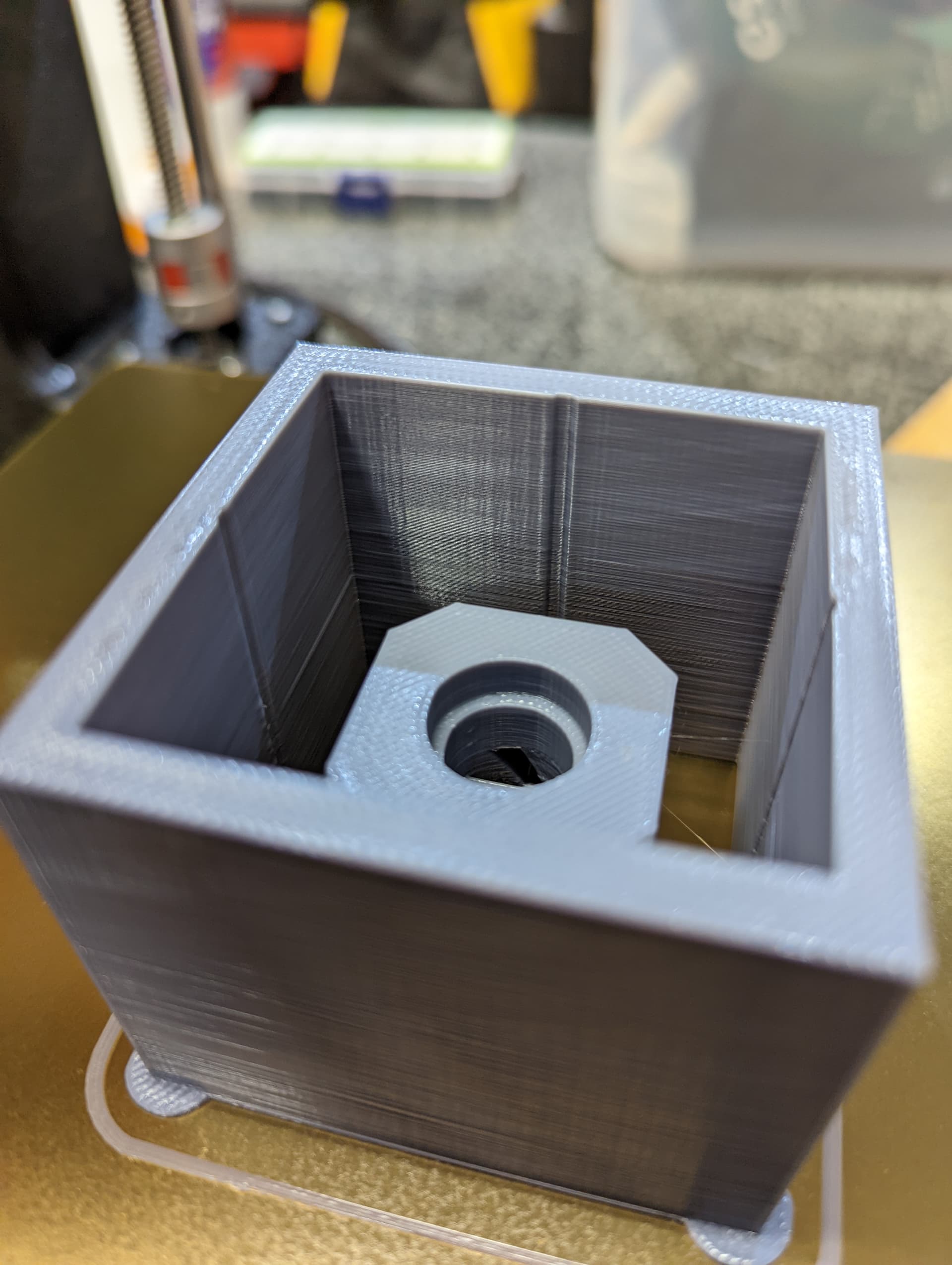
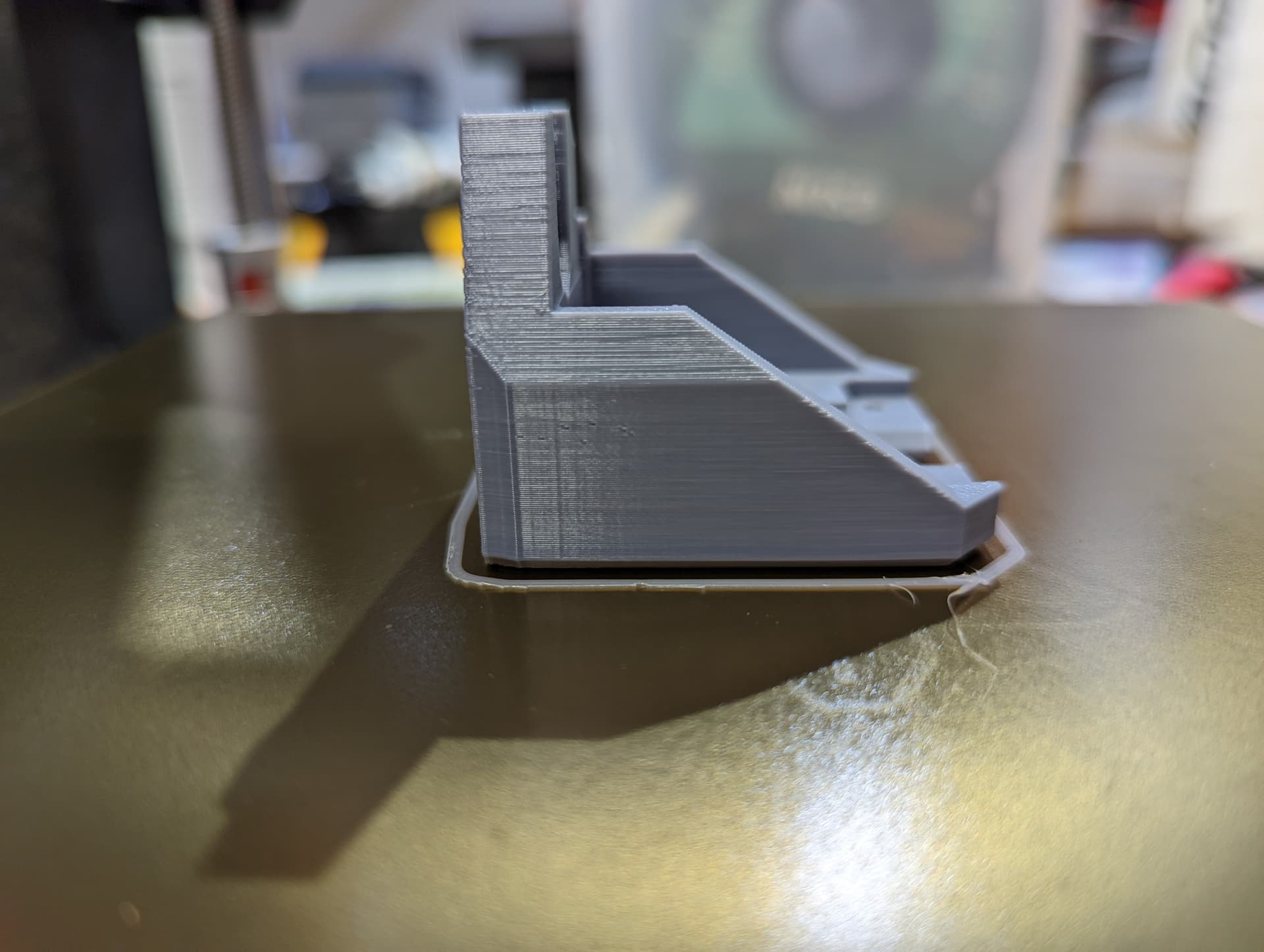
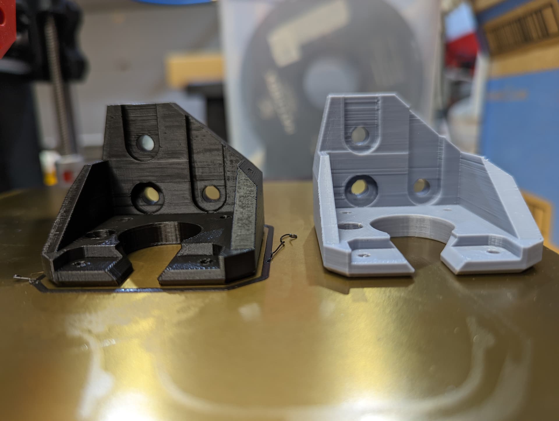
Here is another functional part. Its dimensionally accurate. I think the overall outside finish looks good.
However, the areas where the bolt holes, both front an back seems to have the same issues as the earlier prints.
Definitely better. Maybe try a darker filament 
I said that jokingly, but it could actually be the filament varying in thickness.
Yeah for sure… Gotta love this stuff so so many variables…
I wondering if it has anything to do with acceleration?? who knows… I am going to watch teaching tech’s video on that and see if I learn anything that may help… the part is functional so its a pass for me.
And yes, I have darker colors on the way for these parts I have been printing.
Too high of an acceleration setting can have a similar effect to too high a velocity setting. On extrusion it may prevent retraction. On other axes, at the extreme too high settings will cause skipping steps. At less of an extreme you’ll see the “ringing” echoes around corners.
Hey Chris, I’m sorry, for some reason I was not getting notifications from your thread.
That does look like acceleration and deceleration, can you post a new printer.cfg with all your newest changes?
I’m going back a few posts and try to reply to them.
I have a Hemera on my printer, I don’t use gear_ratio, just microsteps and rotation_distance
[extruder]
step_pin: PD15
dir_pin: !PD14
enable_pin: !PC7
microsteps: 16
rotation_distance: 7.824
nozzle_diameter: 0.400
filament_diameter: 1.750
heater_pin: PB3
sensor_type: ATC Semitec 104GT-2
sensor_pin: PA2
#control: pid
#pid_Kp: 22.2
#pid_Ki: 1.08
#pid_Kd: 114
min_temp: 0
max_temp: 290
pressure_advance = 0.01565
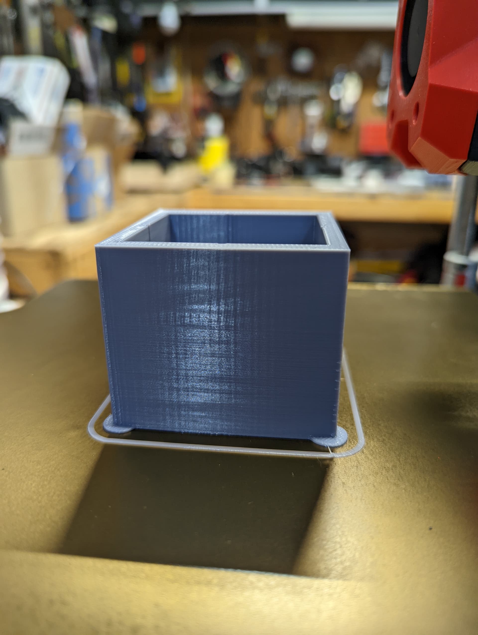
The Picture from the tower test looks great!
And that is because you force the printer to use only SQUARE_CORNER_VELOCITY=1 ACCEL=500
That will not change anything, those couplers are just as good as the spring one, as long your threaded rod is straight.
I agree with Tom,
Here is my printer config, and as you know every printer is different…take my config as a grain of salt…
[printer]
kinematics: cartesian
max_accel: 2000
max_accel_to_decel: 1000
square_corner_velocity: 1.0
max_z_velocity: 50
max_z_accel: 100
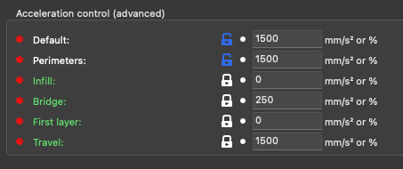
My thoughts are that you should chage your max_accel, start small, 500 maybe? add max_accel_to decel, Klipper Docs say that “usually” 50% of your max_accel is good.
Change square_corner_velocity. The default is 10.0, I left my at 1.0 just like the tower test.
Hope this help.
@gpagnozzi attached is my current config file.
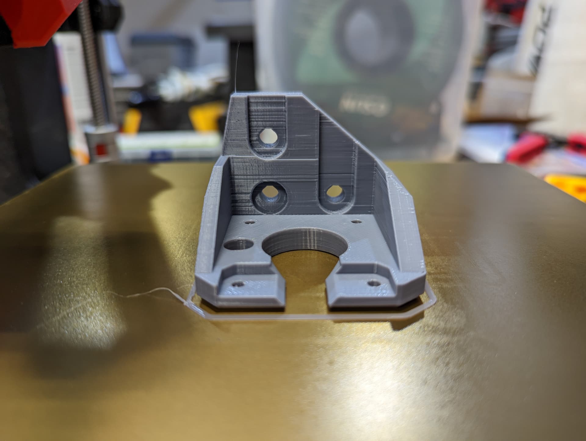
I ran that similar print again today and had the same issue at the holes and where it protrudes out (part goes onto a 2040 extrusion). I had tried these settings: 40mms 500acc , internal 80 - 100mms 2000acc . I think at the end of the day I am just printing way to fast. The printer has a Phaetus Dragon Standard Flow. Today I switched to a different filament and like I said, the banding showed up again just like the prior part .
printer.cfg (2).zip (4.0 KB)
Let’s try something.
Keep your max_accel at 2000
Add max_accel_to_decel: 1000 or even 750
Change your slicer settings a little.
Under Print Settings/speed
These settings will override your printer.cfg max accel
And on. Printer settings/ speed, change all your speeds to the same value, something like 60mm/s
The point here is to try to eliminate those lines/artifacts
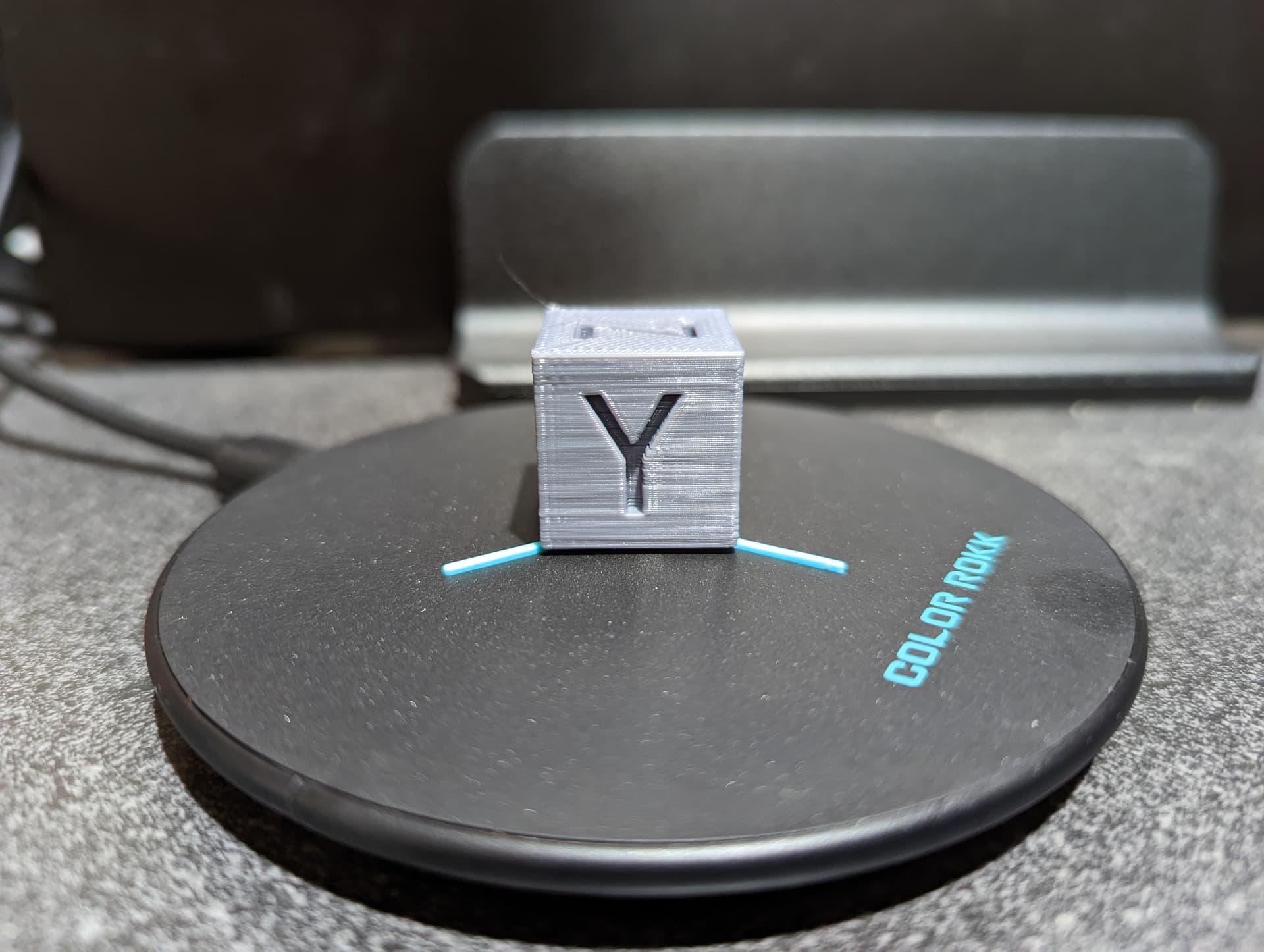
IMHO I think you have an acceleration issue, and it is only in on Y axis base on Klipper docs.
See if that will do anything for you.
@gpagnozzi thanks much for your feedback… I will give it a try tomorrow. much appreciated!
1 Like
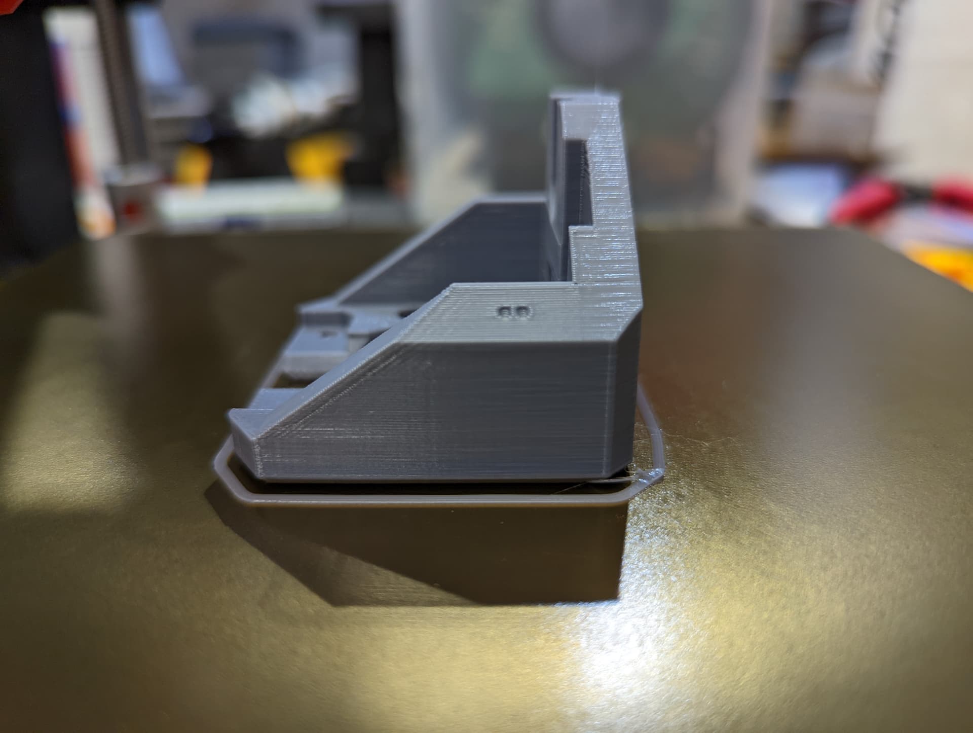
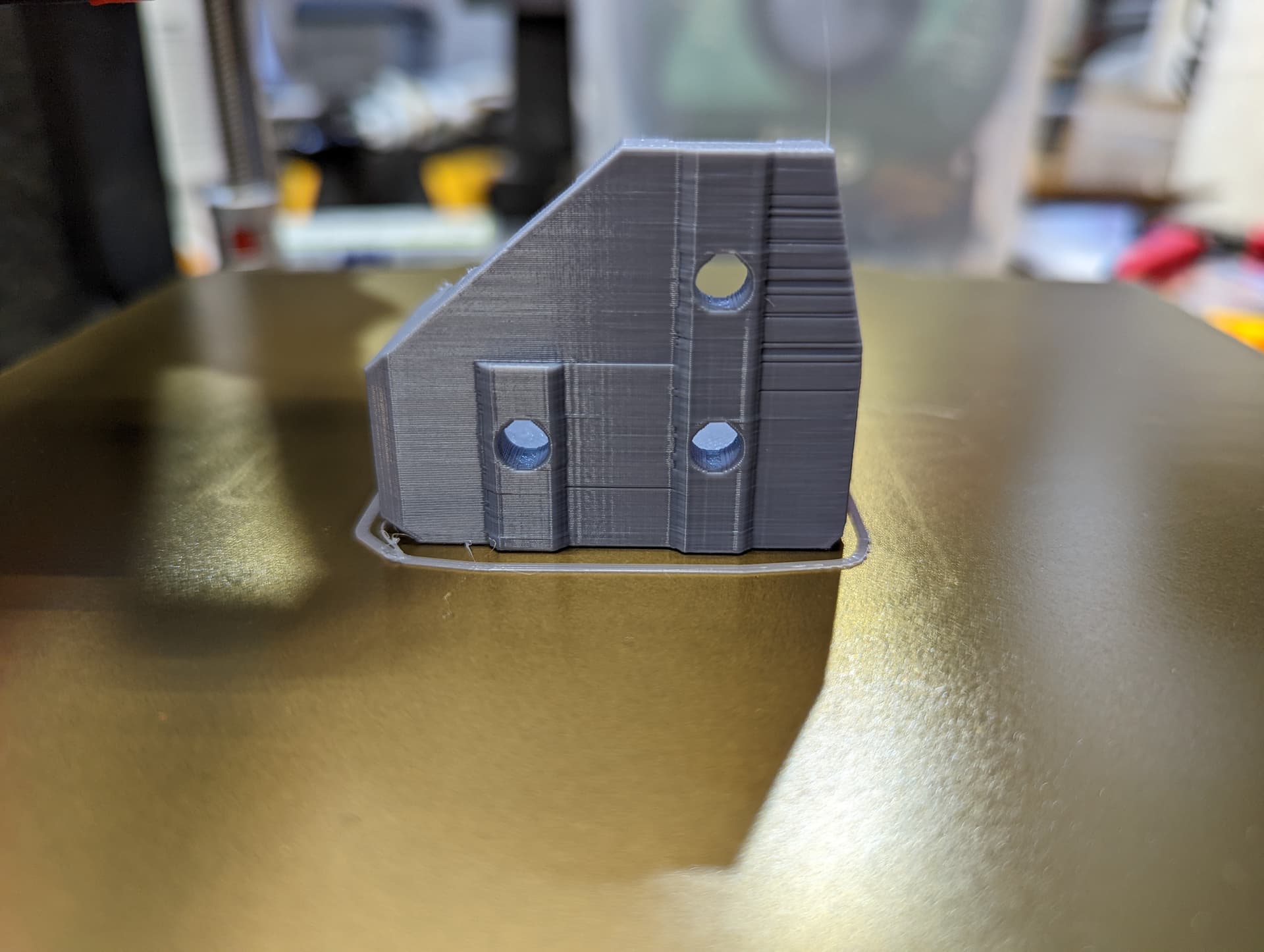
Results are back… seems those tweaks seemed to help … there is still a slight line/shift in layer just before the upper most hole recess.
k
1 Like
Following this thread as I’m getting ready to start my printer shortly.
Which printer are you gonna build ? Are you going to run klipper?
The v2. Not sure what software yet. 
That is a good sign!!
I think you should keep playing with Max accel, lower it a little more, print a test part, lower again until you get rid of it them start increasing your print speed.
Has no one size fits all 