Background:
I was having a little trouble with print quality on my MP3DP V2.
It was a cracked part and couple loose screws on the Y-Plate.
When I went to grab a copy of the Y-Plate parts I stumbled across the Repeat version.
I still proceeded with fixing the V2 and even did a couple other enhancements while I was at it and it is now working great again.
However, I have caught a bug to build a Repeat and have started printing parts already.
I will definitely do a wood frame cut on my MPCNC Burly (Primo conversion now on hold) - 1/2 Birch makes the most sense to me.
The SKR Pro V1.2 with 3.5" TFT seem like the obvious choice along with a Hemera.
While I could salvage a few parts off of a current printer, I am reluctant to tear a functioning one done and will likely just buy all new steppers and build plate / heater.
Nonetheless, I do have a couple questions in my head as I plan things out and would love some advice:
Questions:
Z-Steppers:
I hear and mostly believe the direct drive z-belt provide adequate resolution. However, I am still tempted to try 0.9deg steppers for Z. Good idea or waste?
Ryan has 76oz-in steppers in the shop. I’ll use them for the CoreXY drive and if I put 1.8degs on Z I’ll stay consistent, but if I go with 0.9deg, how much torque do I need? With a lead screw for Z its pretty low, but I suspect quite a bit more holding torque is desirable for a belt drive.
Build size:
I went through the supraguy build. 300mm bed has it’s allure (I already have two 200mm printers) but there were several comments about how big it is. I am leaning toward sticking with the “standard” size, however, I am susceptible to peer pressure . Another possibility is adding just some extra width (or depth) to accommodate a dual extruder (or wiping area). But since a dual extruder would require a different control board that is a long term upgrade that is likely to never happen.
Extra height would be easy, a negligible cost increase and not consume real estate in my shop, but I’m not sure I have ever hit a height limit with 200mm of travel. Any advice on practical sweet spot?
I’m probably getting a bit ahead of myself on these next two, but while the parts are printing…
Case light: I will install something. I am assuming I’ll use a BLTouch probe. I have them on my other printers and like it. However WS2812b case lights would be awesome too. There are limited PWM pins on the control board and most neopixel configuration use the same pin as the BLTouch “servo” line. A simple switched light would certainly be adequate (manual or digital i/o pin), but has anyone tried RGBs with Marlin on the SKR Pro V1.2? Is it worth it? I suppose I could install them and worry about how to control them with gcode later (external controller in the meantime).
Front Marquee: How is the optional front attached? Does it make sense to add some keyed slots, like the back wall? I like the clean look of a straight edge front, but its going to be CNC cut so they don’t have to be full depth. I will probably start using the before I even make/attach the front, but if there are features to add to the side to make that easier or better, I guess I’d like to have them from the start.
I’m going to be tempted to put a top on. I guess I have the same question for that…
Thanks in advance for any suggestions / advice and a huge thanks to Ryan and the rest of the collaborators on the design - it is super elegant!
Its just too tough to resist starting another build isn’t it? I too just started on the same wooden build as you. However I never considered some of your questions until now.
I am not too familiar with the torque requirements involved with this build and it’s stepper motors. I would assume not much torque is required as everything is pretty lightweight and smooth moving. I can’t speak much to this question, ill leave this to someone more knowledgable.
It’s a common desire to want the bigger bed. I would like to build it for a 300mm bed but I haven’t really had any limitations so far with my 220mm bed, so I might as well stick with that. Maybe if this one goes perfect I can convice myself to build another one but larger the second time. I would say unless you are specifically needing the larger build plate for a common part you are printing, then you should stick to the 200mm.
That would be an interesting addition. I have always used an esp32 and Wled to control my neopixels, so I am not familiar with how to integrate it with the SKR board. But if you figure all that out then im ready to learn.
To add on to the tech, a camera mount somewhere in the box may be a cool benefit as well. I personally like to use Octoprint and monitor my prints while I am away so I know i’ll be wanting a camera in there.
If you want the clean/smooth front face with no screw holes then you will definitely need to add pockets/grooves for the side walls to fit in. With these pockets, you could easy just fit this together using wood glue and it would be plenty strong. I just always get nervous gluing things like this because I know I will eventually need to remove it for some reason. You could also use pocket hole screws on the inside of the side walls to fasten a front plate. This would help hide things.
0.9° steppers are probably not a bad idea, but I haven’t seen any issues with the 1.8°steppers that I’m using.
The larger print bed is nice. My machine is a little under 2’ square, but I could have dropped 2" in depth by using 400mm linear rails instead of the 450mm rails that I had. It’s big, but it prints big, too. (I did a vase mode trash bucket 18" around.)
Can’t help you there, I just have a couple rows of 12V LED lights in mine.
Note that this is NOT a part of Ryan’s build. I added it myself. I just have 6 small screws into the 1/2" plywood. It’s not a structural piece at all. I was going to put a top on, but… It’s really not necessary, and actually kind of gets in the way.
It’s a really nice printer. It’s fast, well behaved, and very accurate.
What are you using for a bed heater?
I was contemplating a 120V one with an SSR if I went 300x300, but don’t love the idea high voltage going to a moving part - I have had bed wires fatigue on my V2, but the z moves less and less violently when it does so it might be okay on this design. Also, I have since improved my wire retention and strain relief on the V2 so lessons learned there can be applied.
I know the front is a cosmetic add-on and not necessary, but yours looks great and I like the way you mounted the LCD. I’d at least like to provision for one. It sounds like I can just tack it on after.
I guess I’ll hold off on designing / making the top. It will be easy enough to put a set-in-place cover if I decide its a good idea. I’ll try and reserve some material for it though.
I used a 24V heated bed. https://www.amazon.ca/gp/product/B085BDQX5Z
It’s a bit slow to heat, a mains voltage one with an SSR would be faster, and probably more efficient overall, but this one gets the job done. I have it sitting on 1/2" of foam for insulation. Though it’s zlso sitting on springs, it’s pretty much strapped down to the foam backing.
I like the LCD mount. I was a little worried that the flat facing wouldn’t be very convenient, but it hasn’t been a problem, and it’s not in the way at all for the print bed. Maybe that’s the advantage of having that extra space up front.
I’m considering making 2 more of these. I gave my MP3DP V2 to one of my kids, but now, looks like one more needs a printer, and if I give a different one… Well, you can guess how that’ll go.
It looks like 20mm square carbon fiber tube is not super easy to come by at the moment.
a 440mm length (for a 300mm build plate) would weigh about 100g (1.5mm wall).
1.5mm wall aluminum is available locally and is cheaper to boot. It would be about 130g.
I have 2020 v slot on hand, so it’s kinda free. It would weigh around 200g.
Considering the Hemera weighs 380g by itself, the extra 30/100g is about a 5/15% penalty on the total moving mass.
I realize the center (X) rollers run down the middle of the square tube, so it would have to be adjusted for v-slot, but it looks like it wouldn’t be a huge tear-up - the Fusion model regenerated with only a couple of errors I think I can fix. Plus, I think I could eliminate 3 rollers (part count and weight) by running in the v-slot. The 45 degree rotated orientation of the tube would actually be favorable to CR10 (and the like) config considering the offset load of the extruder mass.
Any gut checks on giving this a try, or should I just get some AL tube for now and hope CF fits the same (close enough) when it shows up in a month or two?
I had the same thoughts on weight of the Al tube, and would have happily used it, but it turns out that around here, 20mm Al tube is either horrendously expensive, or takes even longer to get here than the CF tube did.
If it’s available locally, I’d go with that. In fact, if it were available to me locally for a reasonable price, I’d consider switching.
What is available to me locally is 3/4" Al tube, and I’ve considered making an adjustment to the pieces to accommodate this, but haven’t actually done it.
I wouldn’t go with the 2020 extrusion, V slot or otherwise. Still, I see the appeal, with V slot being what those POM wheels were actually designed for. If you’re going to go to that length of redesign…
The AL tube available locally to me is 3/4" nominal, not 20mm.
There is a Speedymetals more or less on my way to work and they stock it and charge $2 / ft.
I figured I’d measure actual and adjust the hub if necessary - moving the holes in 0.5mm each doesn’t appear to cause any problems in the Fusion model.
I’ll try both that and the v-slot concept when my POM wheels show up. If it works I’ll post the alternate “hubs” as a remix. It doesn’t hurt to have options. This is looking like my most expensive V1 machine yet, so saving a couple dollars on the tube may be in the noise level, but I do like the overall “easy to source” mindset of the designs and would like to support it.
Modifying the CAD to make a center pieces compatible with V-Slot and 19mm square tube wasn’t overly difficult as a hack job, but led me down a rabbit hole to learn Fusion 360 - at least enough to model it somewhat cleanly.
I printed the V-Slot version and it seems to slide pretty nicely. My 3/4" aluminum tube is ready for pickup, so I’ll print and try that too. I’ll also compare actual weight difference and make an executive decision on which to use.
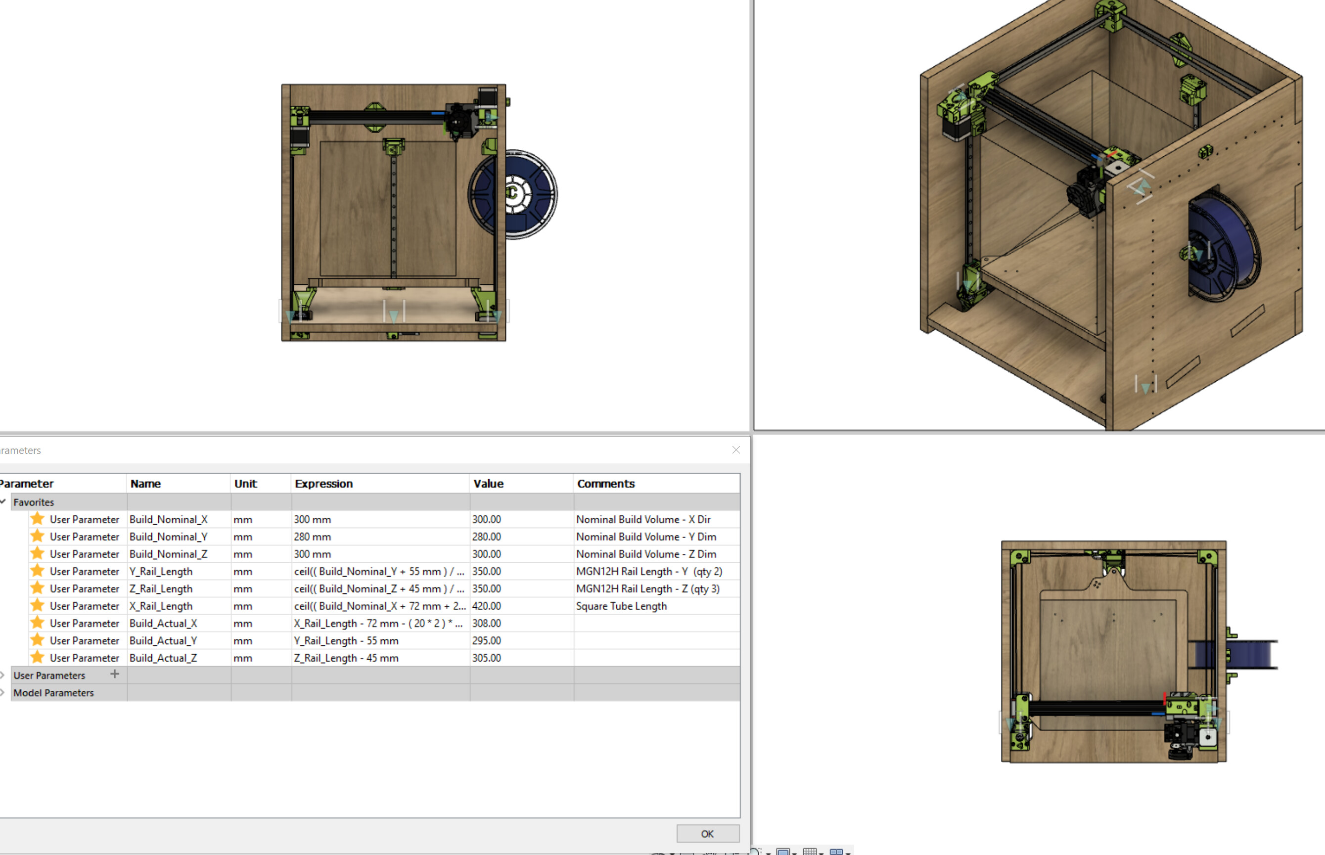
My Fusion 360 rabbit trail also led me to rebuilding most of the CAD assembly. I left off the frame extrusions and tried to parameterize the wood parts a bit more than they were.
I think I am settling on 350mm rails for both Y and Z which looks like it will yield a near 300x300x300 build area with an appropriate X tube length.
To compensate for the simplification of the removed extrusion frame, I added end stop, belts, steppers, extruder and a couple other visualization goodies.
There are a few more features I’d like to add to the wood frame piece models & I am not sure if I am going to layout the electronics so I can CNC the mount holes or just drill them in late, but I am probably picking up material this week and could be cutting this weekend.
I do like the look with a front face plate / marquee, but I think it might overly constrain the Y-Rails if not assembled perfectly, so I think clamping the x-rail with the y’s all the way at the back and letting the front flex a little as Y travels forward makes sense for my skill level. If I see any printing artifacts, it will be easy enough to add/try a bridge or front - I left enough side clearance to accommodate the intended tool head.
On an early 3D printer build, I put together a simple perfboard with a couple of sets of pin headers so that wires from the controller for the thermistor, hot end fan, and part cooling fan all had a “break point” right at the print head. Didn’t do it for the actual heater wires since I didn’t trust the little pins with that much current. Ended up taking it out on the next revision as I didn’t change the tool as much as I thought I might, partly because I got a dedicated K40 for lasering stuff.
I count 15 pins required not including the heater:
4 - stepper
2 - hot end fan
2 - part fan
5 - BLTouch
2 - Thermister
16 pin connectors aren’t too hard to come by: OBC and IDC are 2x8 config and you can cut an extension cable in half for a M/F set that is pre-crimped. Both end up a little bulky though.
Maybe a 4x4 header would work…
The heater wires need to be a bit thicker. And then the fans. Those three can share a common 12VDC pin though, if you really had to.
I really like the idea of putting a daughter board on the hotends and then connect just some control wires (typically CAN) and power (12-24V and ground). There are some neat ones out there. I may try it next time I build a printer.
The CR10S-Pro uses a ribbon cable with a breakout board right next to the X axis motor.
I’m in the processes of upgrading the board as I want pressure advance and or Klipper.
I’m planning to add a 2nd breakout board next to the SKR Pro and use the ribbon cable instead of rewriting everything. Breakout Board
It looks like just about everything I want and nothing extraneous.
It’s only $15 and super tempting, but the micro-fit cable would probably be another $10-15 and /or be a pain to make. Plus there is not much point in doing it unless I had a couple of the Dumbboards to support multiple tool heads, so it is still a bit hard to justify.
What about skipping the 20P micro-fit connector and just soldering the umbilical wire loom to the PCB? (it’s sold un-soldered).
It could be mounted on the X-Slider. You’d have to remove all the JST connectors to pull the tool head, but that is still way cleaner than 7 separate loose connectors and you’d really just need the one Dumbboard.
$19 with shipping, but I’m so deep in this already, I should just stop counting…
 . Another possibility is adding just some extra width (or depth) to accommodate a dual extruder (or wiping area). But since a dual extruder would require a different control board that is a long term upgrade that is likely to never happen.