TLDR;
I made a Lowrider v2 which can use any tubing you like from 18mm (1/2" EMT) to 32mm (1.25"). This version is lighter, stiffer, and likely cheaper to build. It can be made with metric or SAE hardware. Its parts are modular, so a user can change rails with very few changes.
I drank the kool-aid: I love the idea of CNCs as widely available as 3D printers. I give this design freely to the community so that more people can build CNCs. If you’re interested in helping to test the changes, I’d love to support those efforts anyway I can.
Introduction
Back when I started my build, I noticed a lot of users stumbling across an issue of parts availability. Despite the worldwide use of metric parts, the majority of Ryan’s buyers are in the US and are stuck with the imperial system. The upshot is that right from the beginning standardization is challenging.
Furthermore, different markets have different material selections. Sure, everyone has screws and nuts, but does everyone have easy access to the same cheap and highly accurate steel tubing? It turns out not. Some people’s best access to affordable tubes is Ikea curtain rods.
So I asked myself “what if we can design this so as to be modular, so that any sane combination of parts can be used?” And furthermore, what if a modular design sees an increase in machine stiffness, a decrease in weight, and a potential decrease in cost?
It turns out we can have our cake and eat it, too!
After 6 months of mucking around, I’m proud to say it’s all coming together. I’ve been writing about my efforts notably in two threads:
but now it’s time to start pulling it all together.
Current status
Here’s where I am today [2020-12-14]:
I have a 95% model in CAD: Onshape
The missing 5% is the handy mount for the LCD screen, as well as the table and belts. I’ll probably never do the belts unless I start running into issues or am struck by inspiration about a possible improvement.
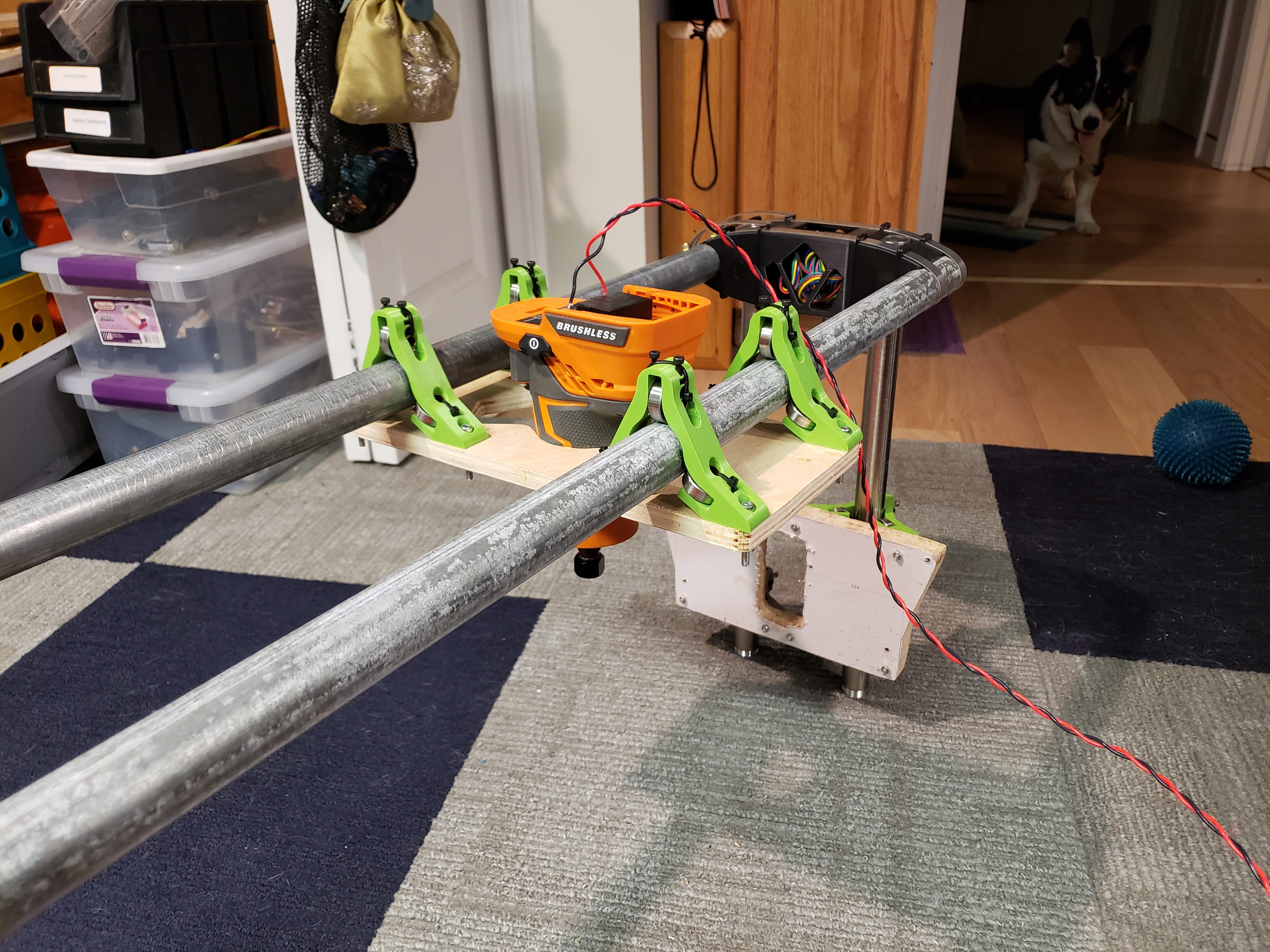
Using the above CAD, I created a first draft build:
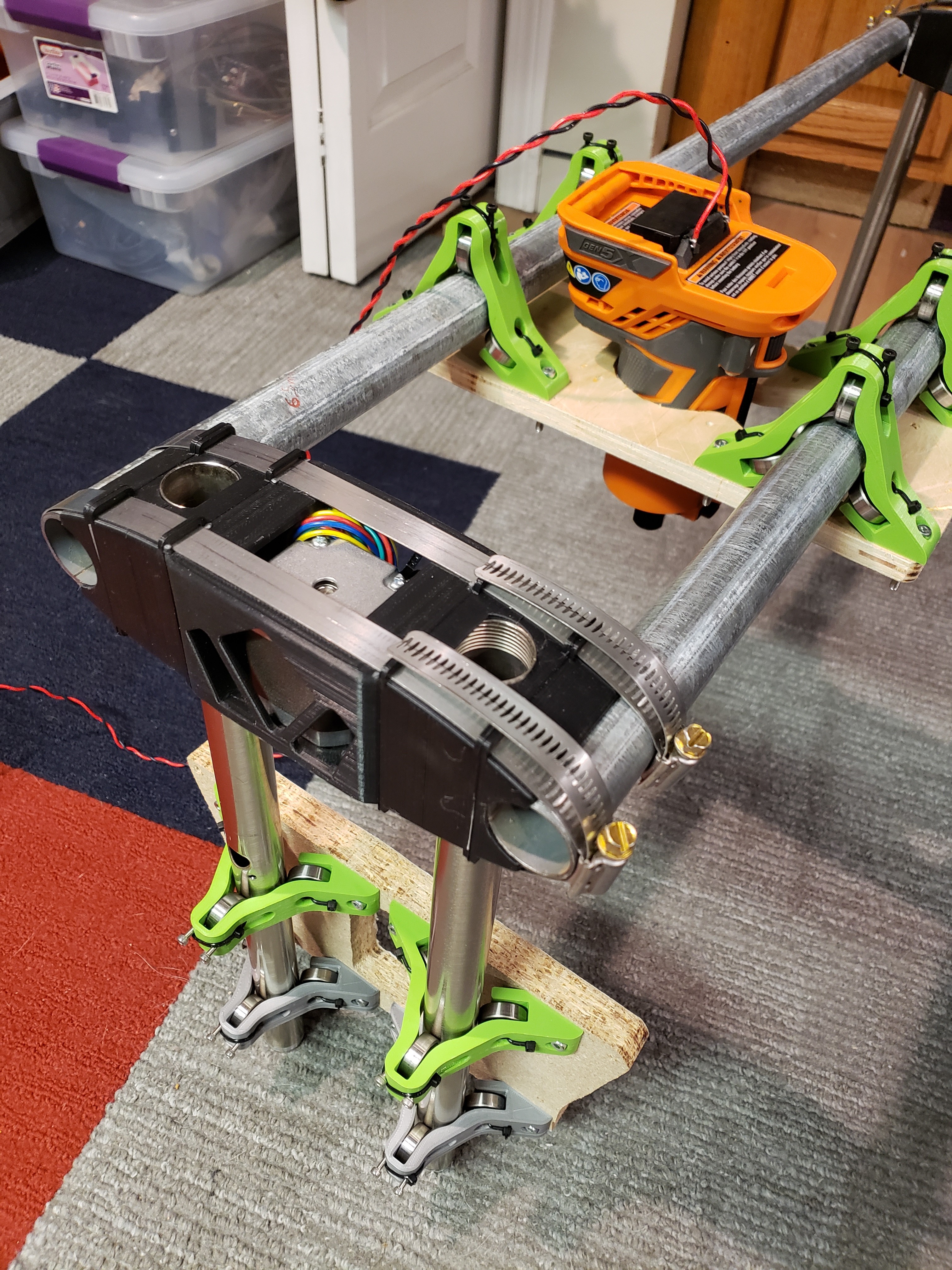
I’m very pleased with how things have come together. Thanks to making my mistakes in CAD, there weren’t too many rough edges to work out for assembly once I sat down to put it all together.
I’m missing a few minor parts, but they’re in the printer as I write this. I am also short a few screws[*] but those are coming later this week as well. I hope to have this together and powered-up by Friday.
I still need to build a table. I’m thinking to throw one together just to have this operational. Plus, while I want a panel-sized router it’s only for one job and then after that I’ll be making small and precise aluminum parts.
Changes
So what’s different? Turns out not that much! I was able to keep the majority of the design, only really changing the bearing blocks and the plate layouts.
- Weight
- In a post I made a while ago, I gave a breakdown of the various moving components in a standard build. It turns out that there’s some low-hanging fruit.
- For the most part, the easy win here was getting rid of all the steel M8 (or 5/16") hardware and replacing it with brass tubing and zip ties.
1. The brass tubing is not precision cut, anyone can do it.
2. The zip ties serve no structural purpose, they simply serve as cheap retaining clips. - By using lighter-weight Z-tubes I’ve saved several hundred grams.
- There is less overall plate material. The X-plate has increased somewhat in size, but this is more than compensated for by the decrease in Y-plate dimension.
- I would need to do an apples-to-apples comparison for the plastic volume, but I think that it’s probably about the same. The modular design forgoes the plastic endcaps, so that helps. Thanks to the fact that everything is under compression load, low infills give very good results.
- For the most part, the easy win here was getting rid of all the steel M8 (or 5/16") hardware and replacing it with brass tubing and zip ties.
- In a post I made a while ago, I gave a breakdown of the various moving components in a standard build. It turns out that there’s some low-hanging fruit.
- Tubing
- My y-axis is 24mm steel tubing I got from an old lamp I had. They’re surprisingly straight.
- My x-axis is 1" EMT found next to a sidewalk. It’s in perfect shape, but it’s also cheap EMT so while it’s straight its surface finish is terrible. I’m expecting it will break in some as the the bearings ride over it.
- Rigidity
- The bearing blocks are no longer cantilevered and are now firmly attached on two sides. This increases bearing stiffness by almost two orders of magnitude.
- The bearing blocks are adjustable, and so can be tightened to eliminate backlash.
- The X tubes are 1" EMT, so are somewhat stiffer than 1" steel.
- The X-tubes and Z-tubes are swapped, giving a wider base for the router. This means that tube lateral deflection results in less cutting bit angular deflection. This should enhance fine precision.
- The individual bearing mounts are a tighter fit than the original threaded hardware, which results in less deflection.
- The carriage wheel structure is much stiffer, resulting in lower deflection.
- Router: I have chosen a brushless palm router. Brushless motors are substantially lighter than normal AC motors. However, a palm router is a far cry from an industrial part, and so this might not last long before the bearings develop issues. But the brushless motors are incredibly more efficient than an AC motor, and this means dramatically reduced heat generation. A system which runs much cooler lasts much longer.
Moving forward
So where do we go next?
I’d love, love, love if some other people can test out the ideas here. In theory, it should all work just like before, only some of the build steps should be easier. Hardware part sourcing should be straightforward and works as easily with metric as imperial.
I’m particularly keen to have an apples-to-apples test done against a standard, well-tuned Lowrider. All this theory is great but until someone can conclusively say “this is better” my job isn’t done.
And If there’s any commercialization to be done, it’s by Ryan if and when he deems it useful. I made this with an eye toward minimizing part count so that kits could still be easily mass produced. My source files are freely available to all.
[*] I could just get some screws from the hardware store but I’ve decided to use partially-threaded screws in order to maintain alignment as the CNC ages. Under the effects of vibration, heat, and pressure, the threads in fully threaded screws will eventually bite into and destroy the holes they run through. This is why fully-threaded structural assemblies are forbidden in aerospace applications.
