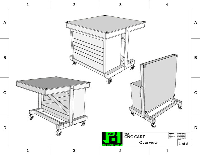
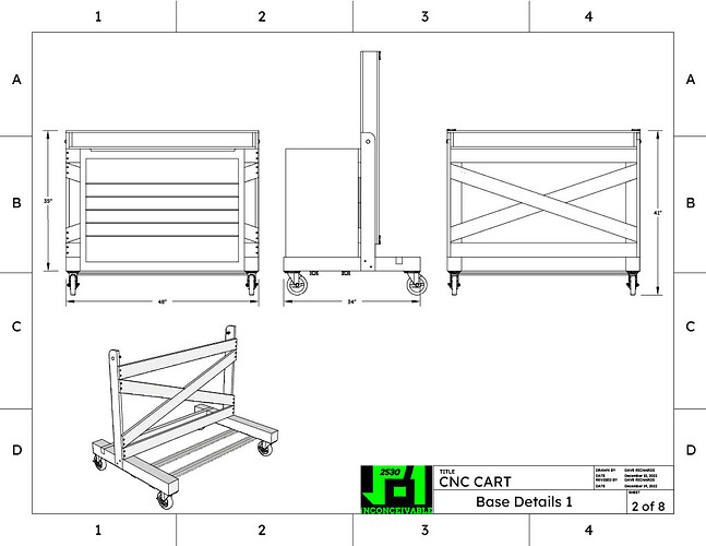
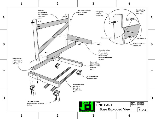
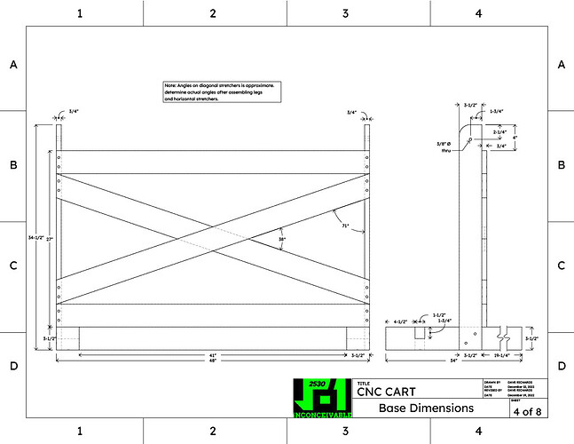
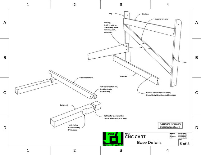
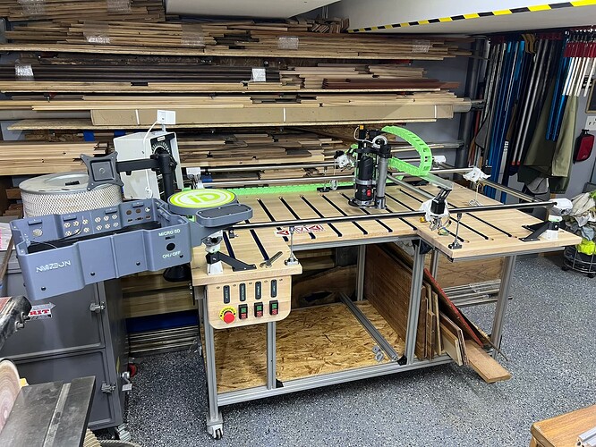
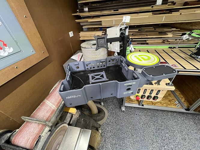
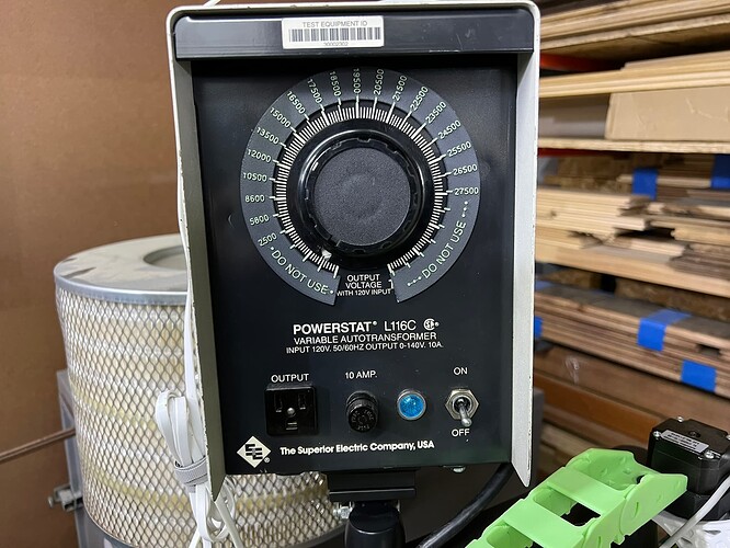
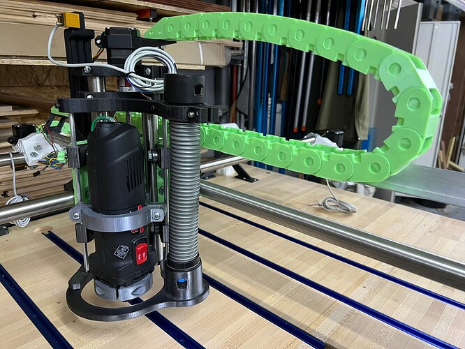
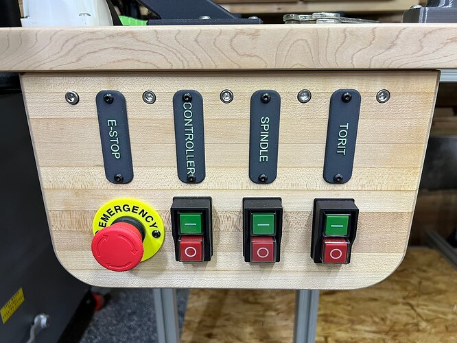
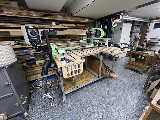
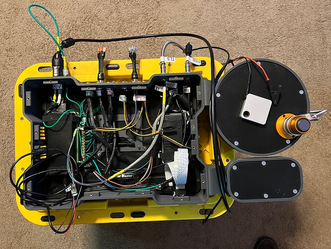
Welp, it’s been over 4 years in the making but I’m finally making progress on this build. Here is the design drawing for the Prim Build. I’ve made some modifications on the fly through which you will see in the completed build photos
1 Like
Here are some Build Progress Photos: 95% of the mechanical build is completed, now on to the wiring.
4 Likes
Man, looks as nice as @bitingmidge’s table. You guys also have the same working speed. ![]()
4 Likes
Your going to love the Primo and the build process! Welcome!
1 Like
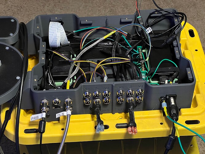
the control panel is mostly wired now too. The next step is to install the Jackpot board, plug in all the connectors, and see if my wiring was correct …or not!
4 Likes
Looks very professional, brilliant.
Well, I hit a snag! got the steppers wired correctly and I can home the machine…but when I move x and y the x1 motor and x2 motor are moving at different rates same for the y1 and y2 motors. such that by 100 mm of movement they are out of sync by like 25 mm. This is causing racking and the stepper motors bind up. I assume I can control each stepper motor independently in the config files but they are all the same motors from V1 and should move at the same rate. any suggestions would be helpful.
Assuming you bought matched steppers the first thing I would check is your grub screws.
Thanks, I check them tomorrow but I made them #$@! tight and put blue lock tight on them so I doubt that’s the issue but I’ll check them all to be sure.
Just double check one of the 2 on each pulley is still on the flat of the shaft too.
1 Like
Yep! But I’m not in a “checking” state of mind right now…I’m in a “chucking” state of mind so it’s best to stay away from the Build for a few hours!!!
A feeling I know all too well.
Don’t worry, you got this.
I see you’re using a jackpot. So, when you’re ready, my next steps in your shoes would be:
Switch the X cables at the board - does the error move (stepper & wire) or stay (driver)
Post your config file here and the collective can take a look and sanity check it for you
1 Like
That’s a good suggestion. For example, I could make what is currently x1 into x2 and vice versa and obviously, i’d need to rotate the 4-pin connectors accordingly at the control board. and see if the problem follows the switch or if the steppers do the same thing even if the wiring is switched.
Presently when I move the X axis by 10 mm …X1 was moving 10 mm but x2 was only moving 5mm.
If I switch the wiring and make the current X1 into X2 if it still moves the correct 10mm then it’s working correctly in both wiring options.
Conversely, if X1 (now plugged into x2) only moves 5mm and now X1 (Previously x2) moves the correct 10 mm then it must be the drivers because the mis-stepping went with the driver switch and did not stay with the steppers.
Welp Updating Fluidnc to the current version 3.9.1 and updating the v1 configs to the current version made the problem go away. Now to get the fluid dial configured in the configs and get the tool length sensor confined with the correct gpio signal settings.
I’m getting disconnected from the fluidnc wifi quite often so I’ll need to find a way to use USB I’ll likely switch to UGS Platform since that’s the software I’m most familiar with.
2 Likes
This is maddening. Trying to get Universal G-Code Sender (UGS Platform) up and running as I don’t trust the webUI and WiFi communication of FLuidNC.
One time everything is working fine and I go about adjusting steps / mm to get the movement distances dialed in. Jogging works fine but then next time Jogging gets skewed and the gantry rails start to bind at the trucks X1 and X2 get way out of sync. same with y1 and y2 one side just seems to be moving at a different pace than the other causing racking.
I’ve upped the amps of the stepperrs thinking that with the larger machine the torque needs to be upped. then it works fine…then next time the racking comes back. Its very frustrating.
1 Like
After the “racking” occurs and I turn off power you can see the gantry “self adjust” back to it’s relaxed position. So the steppers are moving at different rates or the trucks are so far out of wack that each mm of movement is amplifying the mis-alignment such that after 100 mm the trucks are binding and the steppers don’t have the power to overcome the binding and lose steps.
does anyone have some suggestions where to look for (construction) or mechanical issues?
Are the trucks too tight?
Do I need to re-check square of the x and y gantry rails ( I thought dual endstops) would accommodate a bit of mis-alignment!
I’ve double checked the squareness of x and y and the end stops are perfectly equal distance from the corner blocks on each side so before turning on the machine I manually (square) by using the x and y up against the end stops.
I’m running out of brain cells to burn up on this!
