If you already have the pi then you can “just” download kiauh and install klipper. The setup time is in the printer cfg file. I just got mine wired up but havent run it yet due to other demands.
@MattMed jealousy over the waterjet… That is pretty sweet.
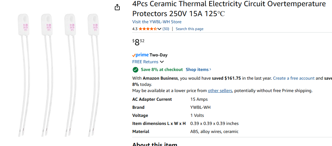
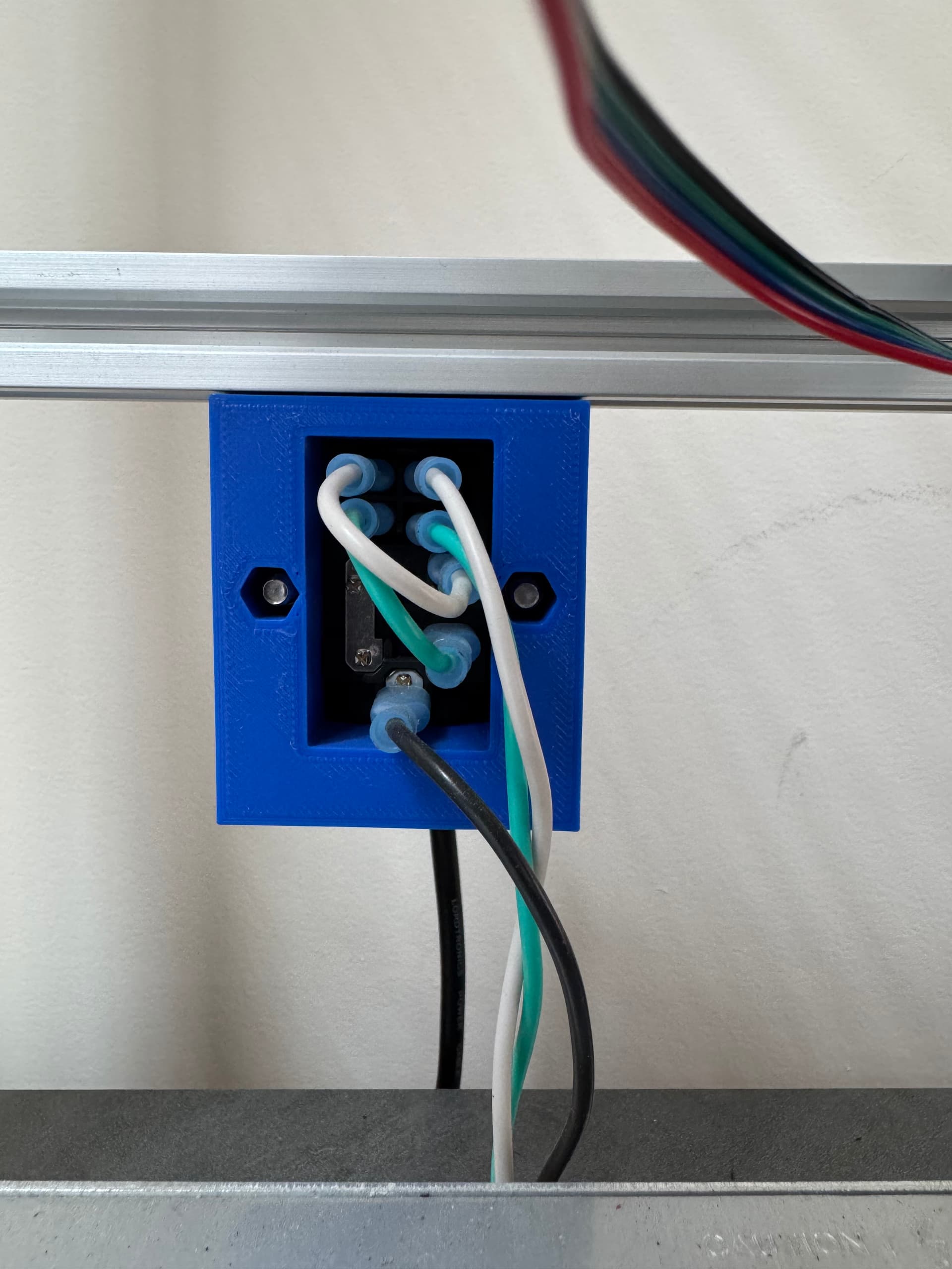
If you mean these, then yes I do plan to use them. I haven’t really figured out the wiring for the bed stuff yet so I am not sure how to use them. But I will.
The thermal switches go in series with your bed power so it cuts the power then they get too hot. Some go to a high resistance state and cut the current. While others are a metal piece tha buckles and completely disconnects. Wire the hot lead from ssr to the thermal protection switch then to bed.
What temperature is this fuse measuring? Is it cutting the power when the current carrying cable itself gets too hot or when the bed gets too hot? For the bed, I thought the thermistor tells the controller when to stop bed power.
Also, what wire gauge are you all using for mains power? I have some that I pulled out of an old monitor cable, but it seems to be a bit thin, maybe 20AWG.
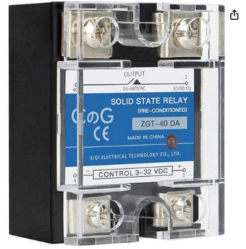
If the thermistor de-laminates from the bed, but still provides a valid temp, then you have a runaway. Same if the SSR shorts. The thermal fuse works in these circumstances to cut power.
Correct. That is how it “should” work. But I have personally seen SSR’s malfunction and controler boards. A fuse like the one you are using has saved me before.
Overkilled, used stranded silicone sheathed 14AWG from power outlet to WAGOs. Then 16 or 18 stranded AWG to other components. I just ASSume my amazon purchased wires are not what they claim, so I often end up using thicker than needed to compensate. I appreciate some people test/verify wire resistance and dimensions for critical projects, but that’s a level of due diligence that’s beyond me.
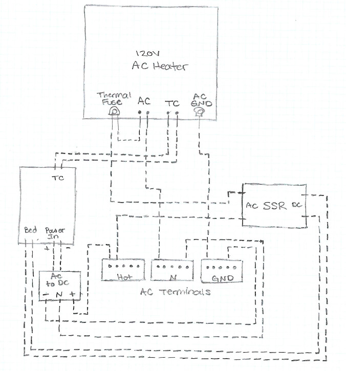
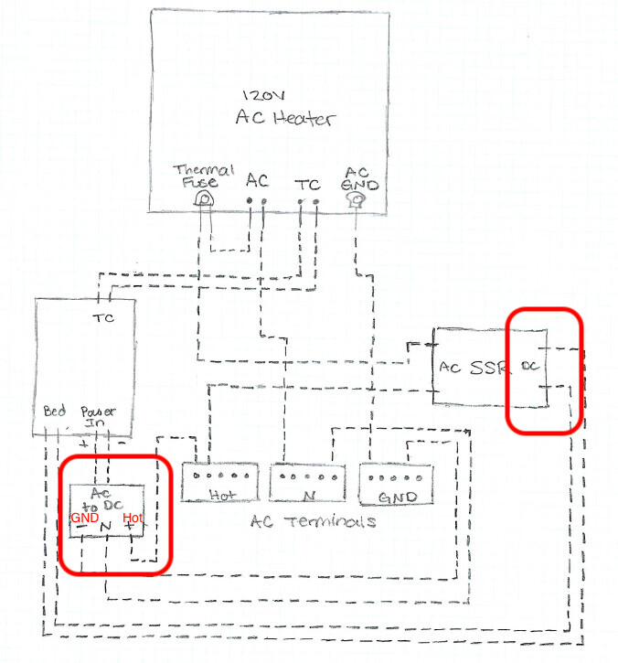
I drew up the wiring for the bed because it helps me visual it. Really not as complicated as I thought. Can someone confirm this is correct before I start running wires?
Yeah I just put the +/- on the power supply on the AC side because I was lazy and didn’t want to squeeze in GND and Hot lol. But the terminals are labeled Hot, N, GND.
Yeah I also didn’t show the AC power in due to laziness plus I am confident on how to wire that in. I will be using the Rocker Switch that I posted earlier, which I have wired up on numerous other projects before already. That has a fuse in it so I should be good there.
Next question. Can I cut the silicon heater at all? I know I saw someone said that they did a little bit. I have a 12" x 12" bed with 300mm x 300mm heater. So I have very little room around the heater for the holes.
Can it be cut? If so, how do I do it safely so my whole bed doesn’t become a human bug zapper?
I will have to check around and see if I can find one. The only ones with mounting holes I can find are in a square pattern, not the triangular 3 hole pattern the V5 is designed for. I suppose I can add extrusion pieces to the bed frame below to allow for the square pattern.
Or also, I could make the aluminum bed plate 13" x 13", right? I have an unlimited supply of stainless steel at work I can use but no aluminum. I can cut it to any size I need. I know its not as thermally conductive as aluminum, but I think it could still work. Perhaps I could use 1/8" stainless. Thoughts?
If anyone has a good source for a AC Silicone Heater about 280mm square then that would be great! I have found one on Amazon but it is over 1 month delivery. I’d like to get something sooner than that if possible.
No idea what’s recommended best practice? But I ended up mounting 1/4" Alu plate to 1/4" plywood using 4 holes, and a heater bed with 4 holes. Even though the Ply bed support mounts at just three points. Am using the common adjustable bed leveling springs, I like how this A) enables me to mostly level by hand, so the auto Z-Tilt before each print does very little adjusting (fast…), B) the firm but still springy bed has some give that makes nozzle and bed scratching less likely when I fluff-up GCODE/motion command.
When you get to configuring Z-tilt, consider trying out 4 point and 3 point Z-tilt. Personally found 4 point Z-tilt results in less overall plate variance (for my build…).