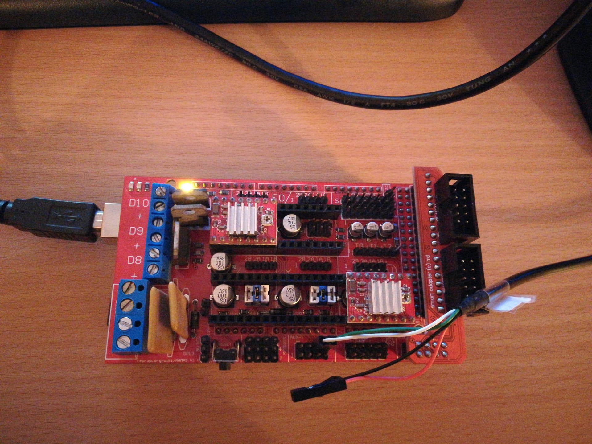
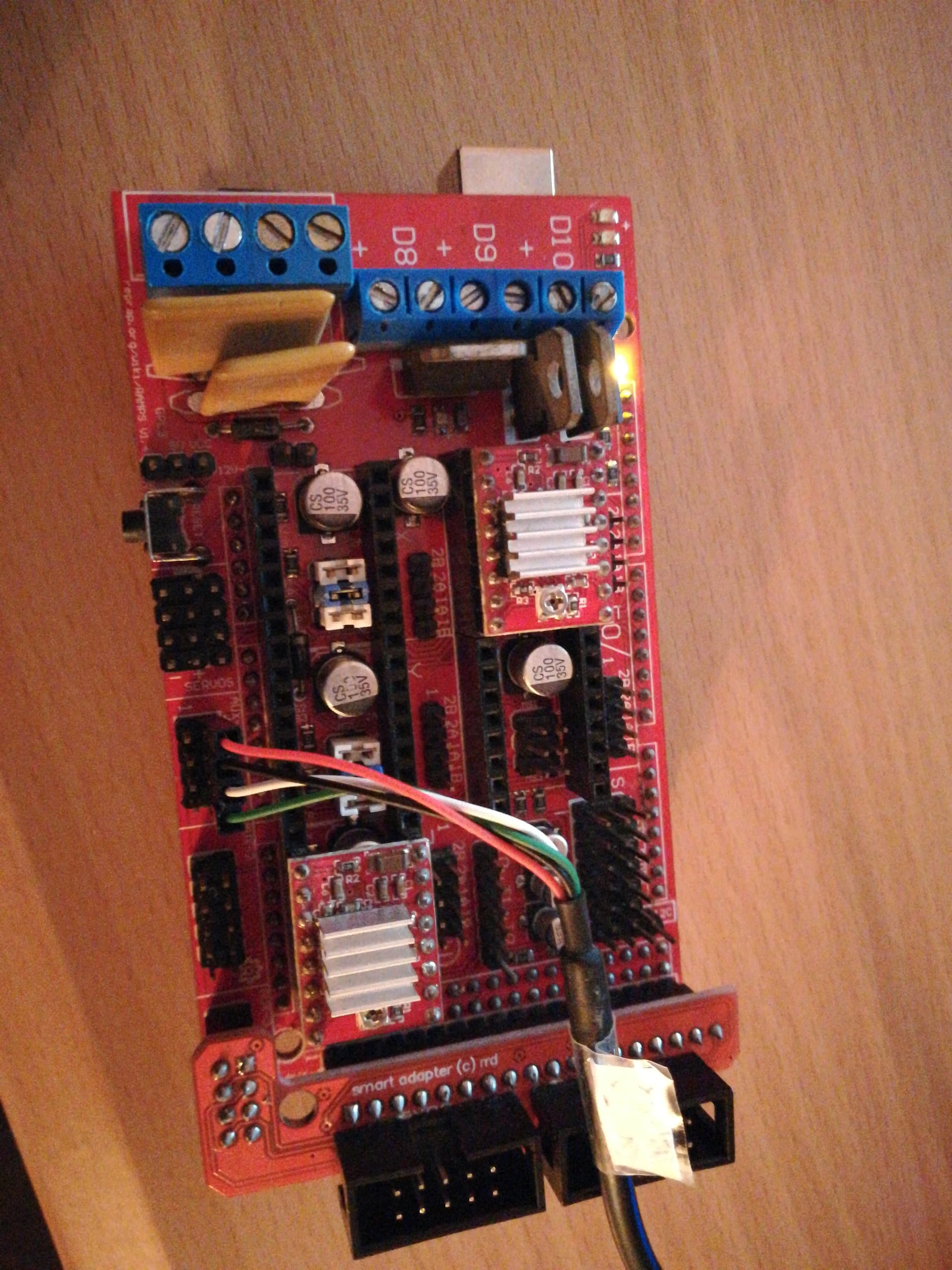
Do this. Your USB-RS232 cable (I’m guessing) has 4 wires (red-black-green-white???)
Usually black is ground and red is 5V. If you have a multimeter you can confirm this. Of course the cable manufacturer might have chosen a different wire scheme but that would be misleading.
Your left with white and green.
Plug any of them to AUX 1 Pin D0 on your RAMPS14 (it will be configured has an input). Send a G0Z1. If the printer moves that is your cable TX. If not try the other one and resend the Gcode. If it moves you found it. plug the other wire on D1.
By the way if you connect both USB cables (the one on the mega and the USB-RS232) to your PC you can leave the USB-RS232 GND and 5V pins disconnected that it will work just the same since the board is connected to the same GND ref via the Mega USB cable.
I only ended up giving it a quiick spin with the new master branch,
I tried connection all 4 of the RS232 cables but apparently im missing drivers for it.
Tried the single pin check on D0 but both green and white excecuted movements i sent.
Anyhow, more importantly, the printer runs very, very smoothly! So much quicker, homing is back to normal speed, no stalling inbetween movements. There is a deceleration towards the end of a move but the rest looks great. That is with the stock master branch, ill try the tweaks you mentioned when im back on it!
Haven’t measured precisely for planarity yet but it looks very good!
The printer accepted moves because you probably sent the commands via the main usb port of the Mega (my guess). You should select the new available Com port when you connect the new usb converter on the open Pilot settings.
Also that final deaccel is fixed in the Master. You can fix it in the bastardazzo by enabling USE_LEGACY_STEP_INTERPOLATOR option in the cnc_config.h (line282).
EDIT: I only realized you were referring to the master branch now (and not the bastardazzo branch). I’ll investigate that deacceleration. Can you post a small video about it? Maybe something in the planner.
Will send you a video np! But it looks very good regardless of the deaccel
Yeah the thing is when I go into Device manager, and check the port it says im missing drivers, by itself it wont find anything, is this what im looking for maybe?
Exactly. If the driver is not recognized it won’t be listed. I’m doing the last touches on the code for the final release version 1.4.
Mainly I’m modifying the software limit check for all kinematics. For Delta this will be an equivalent cylindrical volume. The radius of the cylinder will be based on the Delta Arms and radius ($106 and $107 settings) and settings $120 and $121 will have no effect. For other kinematics the default behavior will also be changed to a bounding box that has it’s origin in the home position and extends towards the travel work volume.
I’m also thinking other aspects of the firmware, like if I’ll add some kind of default parking motion or leave it as it is, since it can be individually implemented for each tool.
I tested on a PL2303HX I have and worked. Plug it to RAMPS and it was running OpenCNCPilot fine with a poll of 100ms.
My other cable actually has a CH340 that comes with the Arduino clones.
EDIT Summited patch 162 with the new kinematics boundaries check. To enable it soft limits must be enabled. As explained for the Delta it will check motion within a cylindrical work volume. All other kinematics were also improved with this concept of workable volume.
Yeah I have a few options/ideas. Mainly I want a very simple effector with as little as possible close to the nozzle, much like the non-planar 3d printing setups.
At the moment I have the switch probe that came with the printer, its currently set up as a 3pin switch, ready for a spin and tests in the meantime as i think of a more final setup.
Ideally the probe would be the nozzle, for ease of use, and to have a small surface of probing.
For example the Super Pinda sensors on the prusas are cool, but they have a wide surface of probing which isnt ideal.
The BLTouch works really well with its low resistance but it would be separate to the nozzle and add to the bottom of the end effector, in case the nozzle is too hard to implement i think ill go for a BLTouch.
Not against IR sensor probing but it ends up being very close to the nozzle.
Piezos seem like a good alternative, there is this kit that translates the piezo signal to something like a switch, and its possible to regulate it from the pcb instead of software. (possibly tthrough software too not sure). Paired with the pcb i could use a standard piezo or these as part of the end effector (rahter than the printbed where theyre usually used).
Sidenote: just an idea but ive been thinking of a different probe, which instead of probing prior, probes during the print. Meaning, if im printing on a curved surface, its like a height follower which adjusts the height of Z to always keep the effector at a precise distance from the printing surface. This is commonly used in metal lasercutting where the metal tends to bend under the heat applied to it. Im just throwing this here, let me know what you think, im aware it might nnot make sense/might be unecessarily hard to implement on delta kinematics
That is wise. Use a simple switch and test the surface mapping capabilities of OpenCNCPilot or bCNC to see if it meets your specks in terms of following the mapped surface.
Again without knowing much of the final application you are targeting, I believe a kind of renishaw probe is what you need. It detects surfaces on almost all directions. I have a printable version of this type of probe on Thingiverse.
I get your idea. That would be a real time height correction much like THC for plasma cutters. The only downside of that is that that will require an other custom firmware modification . I don’t mind another challenge but like this delta kinematics HAL it will take a bit of time. µCNC is mostly ready to quick prototype custom modules to it, soo it’s not a farfetched concept.
Yeah I remember you sent a link to your magnetic probe, pretty sick! I’m down to print it and have it, got some magnets in hand too rn. This one correct?
What if it was an override rather than a correction? Really not targeting this type of probe but trtying to understand how it would be implemented
That’s the one. Although just a concept probe (not a finnished design) I think it might fit your needs. It’s super sensitive and triggers from contacts from almost any angle (like a half sphere detection zone).
The concept of override on the board in realtime would be strange (at least in my head). How would that work??
Walk with me on this one. You want to probe and execute at the same time.
That would mean probe the current position and the target position, go back and execute the command modifying the height/direction of the motion. That would be a very strange back and forward motion. An alternative would be to pre-map the whole surface (either to the controller software like OpenCNC does or in firmware like Marlin does) and then draw with over that pre-mapped surface effectively overriding the heights to try to follow the surface.
THC works with (almost) realtime height compensation. As it perceives the surface, the height of the tool is adjusted to try to maintain a certain distance to the target surface (usually a stationary distance).
Both have pros and cons.
The pre-mapping can effectively override distances like you said and is computed in an early stage of the gcode parsing and motion control and follow (more or less) the surface contour. The disadvantage is that the surface mapping detail depends on the size of the sample grid. A finer grid will eat up memory like crazy. A courser grid will have less detail and rely on surface approximation/aliasing technics that also consume some CPU cycles (bezier, splines, whatever). A way to overcome this computational/memory overhead is to transfer that job to the PC. First map the surface back to the Gcode sender, then the gcode sender modifies the coordinates prior to send it commands to the controller, thus overriding the original gcode that was loaded in the file.
The realtime correction does not require mapped surface. Very little memory consumption. CPU cycles would also be light (maybe a simple PID would be needed). The downside is that the correction would always be done with a “delay” depending on several factors like speed and distance of the motions. On µCNC that delay would be somewhere between 50-250ms that is the size of the Riemann interpolator frame/window and interpolator buffer size (if not modified in any way at least).
Yeah I see. Interesting pros and cons on both.
But im slightly confused why a pre-mapped surface would be so heavy for memory? Wouldnt it map it, approximate it/mesh it between points and then replace it in OpenCNC and have all the gcode precalculated for the mesh, Rather than relcalculating during execution?
For reference, what do you reckon would be a grid thats too fine in my case? Since im not relying on a flat surface this will make a significant difference.
I guess it would make much more sense if it was a separate Z-axis, like in non delta machines.
This machine would work as a “plotter”, so no layers up like 3d printing or down like cnc-ing would be required and no further recalculation of the Z axis after the first layer.
Continuing on my brainstorm, a double Z axis, lets call it W axis could help with this. Pre-probed using X Y Z towers and then the W tower, found on the effector with 2cm of travel lets say, can correct the Z axis discrepancy (within millimeters) independently of the rest of the print/movement. With an IR or linear potentiometer that aims for a certain distance at all times.
This would be bulkier, heavier but its just in the back of my mind as it would be kinda cool looking hahah. I’ve though it different ways of implementing this but the more i think about it the less i believe thiese methods would increase the precision enough to justify the complexity
I don’t want to step on your toes. You’re having a great conversation that I am loving reading. I would advise against the real time measurements.
Measuring against a solid, mostly flat surface can increase the precision considerably. Measuring against the top surface of a print is just not going to be as repeatable.
Real time control gives up the certainty of open loop. I am reminded of those open loop stepper drivers that were popular a year or so ago. The stepper motors we use are open loop, but they have certainty. They know exactly where to go. The closed loop steppers give up that precision and instead have a big dependency on a less precise encoder, and the software of the control loop is “fuzzy”. It decides things based on proportions. One erroneous measurement and the thing takes a long time to settle. And there is always noise in a sensor. Open loop has no noise (until you cross the threshold of missing steps). That’s not a perfect analog, but the premapping measures 50-100 (or maybe more, if you’d like) measurements with millions.
There is a lot of dynamics involved when printing. Those things moving around, at high speed mean that a) You will get errors biased on the movement and b) You will have a very hard time debugging issues.
The first layer on a print needs to be laid down precisely. A difference of 0.02mm on a 0.2mm layer can be the difference between sticking or not, warping or not, jamming or not. The next layer doesn’t have to be as precise (because it isn’t sticking to the bed), but it’s an easier challenge, because the last layer was placed by the printer. Just following the same curve you just had, but 0.2mm higher is easy. Measuring the last layer (with millions of measurements, and each one with some error, and sometimes huge errors) is just letting in more problems. By the time you pull the print off of the printer, an error (or a correction, due to the mesh) of 0.02mm is not going to be measurable. It is only important for that first layer stick.
Premeasuring a mesh and correcting for it in the firmware would be the most flexible. You can drive a machine like that from several sources. On my printer, I don’t probe the print every time. I do it when I change anything about the bed, or when I change the firmware, I have easily gone 6 months without probing and it prints fine. I can inspect these probe values, but more importantly, if I get an error during probing, I can see it in the print and make a new mesh by probing again. Once I have it right, I don’t let new measurements affect the mesh. Of course, the firmware is the “most expensive” to debug and test, and it is the most limited CPU in the chain. Klipper does a decent job of balancing that by putting these functions in python, but it is still part of the “firmware” component.
Measuring in the gcode sender like openCNCPilot or bCNC would be the next best thing. But you’d be stuck with those tools and learning their systems. But at the end of the day, if the problem is solved, it isn’t a high priority to solve it again.
When I said as a more resource consuming solution I was referring to the one based on pre-surface mapping done in firmware/controller board (a bit like Marlin). Points would be stored in memory. Each point would eat about 4 bytes. Let’s say you want to scan a surface area of 10 by 10 mm with a detail grid of 1mm. That’s 100 points or 400 bytes. 100mm by 100mm with the same mesh is about 40kbytes.
RAM on these devices is limited so you get the point. Also computing the adjustments between point (even using a simple linear gradient) will eat precious CPU cycles. This wold have an impact on performance (even more on the 8bit Atmega MCU driving a delta).
The PC solution on the other hand (that was the initial goal via OpenCNC or bCNC) is very doable…In fact it’s already done…It’s just a matter of testing with the current setting. Define your mesh on OpenCNC and it will scan that grid of points via G38.x gcode and read each scan. The PC will adjust gcode to match your scanned surface. That is transparent to your board firmware. It will only receive gcode commands and execute them as usual.
A fine mesh is very relative. Again you will encounter technical limitations with this type of scanning.
Depends on how much detail you want to capture and the size of the object. Scanning a surface is also a time consuming task so remember the more points you scan the longer it takes.
That’s why 3d photo scanning or 3d surface interpolation based on image processing software is the go to tool for this. Graphic card GPUs’ eat pixels faster then a bunch of kids around a bag of chocolate chip cookies but I’m guessing you have a specific reason to want to do the scan this way.
Again my advice (and like @jeffeb3 said) is for you to play around with the existing Grbl ecosystem software in terms of surface adaptation OpenCNC and bCNC are 2 that do that. This is the simplest more straightforward aproach.
The “realtime” solution like I (and again @jeffeb3 said) has a delayed reaction. It’s good enough for plasma THC but not for 3d printing (like the 1st layer problem)
EDIT This reminded me of an old piece of software that I used a long time ago called G-Code Ripper to deform gcode to a non flat surface.
@jeffeb3 interesting breakdown on where and how it would not succeed, good to know thank you!
Indeed this sounds like the best and easiest option for the case. Ill be trying it on a flat surface with the switch probe as I make your renishaw one.
Yes this is what i was wondering!
interesting, ill look into this
Makes sense but wouldnt it require a lot more fumbling?
The question is more will it do what you need it to do? To do it…does it do in one step, or do you have to go through multiple tools to get the end result? How hard are they to use or do they need to be fiddled with?
These are a bunch of questions you may have to find out by reading and testing. I’ll give and example.
Meshroom. You take a bunch of pictures with your phone or camera and send them to the app and boom you have a 3D model. Easy right?? Can that be used as a surface map? Maybe not directly.
You then have to somehow take that model and convert it to your offset map. What app to use??? I don’t have an answer to that. Some times tools exist and are relatively easy to use. Other times they are scattered. And sometimes either you can pull them off your self by coding or hit a dead end.
Again depends highly on the intent for your particular application.
You can even try it with a simple switch and a basic surface with small reliefs or a shallow curve just to see how your setup adapts. I can’t vouch for bCNC, but OpenCNC is super easy to use and I’ve used it in the past to mill PCB’s.