Marlin Surface scanning on a Delta 3D printer - help

Yes because of these settings. If your motors have a setting of 80 steps per mm you need to divide (not multiply has I stated earlier) the number of steps output with $P command by that value setting value to get the traveled distance in mm.

The equation is:
tower travel in mm = tower steps / steps per mm

Now about the motions:

It’s the expected behavior. Even without homing the machine assumes an initial position. So motions during homing have output values also. After homing is finished all positions across all internal core systems of µCNC are reset and synchronized (including step positions).

After changing the values did you do a soft reset? If you did a hard reset did you saved the settings in permanent memory with $SS command?

I’ll investigate this a bit more. I’ll recheck my math. And do some more testing and I’ll let you know.

Yes I did rotate all the coordinates and they will not align with the previous one. But it’s just a matter of reference I guess. This was just to match the simulator so I could have a more direct conversion to the simulator reference.
With Marlin did you remember if any of the towers were axis aligned? Which one? With which axis?

EDIT: The simulator looks fishy. I only noticed now that the Y arm does not have a fix length and the values output for the towers do not match the motion of the tower points. :weary: This was referenced by the reprap wiki but I guess it’s not reliable and the one from thinkyhead (Marlin) in not available anymore. I’ll try to figure out a solution…

soft reset, made sure on the $$ that the value was the one i tested each time

dont remember but ill find out

The forum i asked for the $106 and $107 told me to measure each arm because the printers from Flsun are relatively low quality and there might be some discrepancy between them. someone else suggested that on Marlin this doesnt matter, told them its not my case but they mentioned G33, delta calibration, which is what i was talking about earlier saying how it homes and then calibrates the bed and knows where it is in space. Well aparently this also fine tunes the values $106 and $107 based on the machine itself. Dont know if this can be implemented in Gbrl but it seemed interesting as an idea

1 Like

check the second image on this, oddly familiar id say :thinking:
http://boim.com/DeltaUtil/CalDoc/Calibration.html

1 Like

Yes I guess it’s possible to implement that. I’m guessing some more advanced triangulation/trilateration and some other math.

You will need a bed sensor (like a probe).
You will always need some sort of reference values though (I believe) and/or a set of constrains (like arms with same length or tower forming an equilateral triangle) or else the math will be just nuts.
While I’m trying to solve the simulator problem I’ll try to think about that subject also.

EDIT: I think I’ve fixed the geogebra simulator. I barely know how to operate the geogebra app but I’ve manage to fix the error. Here is the link. I’ll recheck my previous results now.

EDIT2: This will be a bit long but I’ll try to keep it short.
The results seem to be correct. You can test it your self.

Just to make sure the towers are moving the expected distance please run this test.

  • Insert the same values for $106 and $107 on the simulator and on your printer.
  • On the simulator take note of the towers initial position (they match for all 3 towers) - lets call this Hini.
  • On your printer do a home motion then send the efector down to gain some headroom. Mark the position of all 3 motors (they should all be at the same height).
  • Do a G0X40 on the printer. Now measure the traveled distance by each motor (positive if above starting point and negative if below).
  • Do the same in the simulator. Again calculate the traveled distance for each axis by subtracting Hini from the current position that was calculated by the sim.

See If they match. This will at least tell you if any step skipping is happening. If not my guess is that parameters $106 and $107 are incorrect.

2 Likes

Someone mentioned to measure all arms and get the average length, not perfect but bettter i guess?

Btw, would you need to know either this distance
image

or this one
image
as well as $106 anf $107?

1 Like

Check the previous post. $106 is the longer radius subtracted by the smaller.
It’s distance a in the simulator

1 Like

Writing as i do: this turned out to be a long one

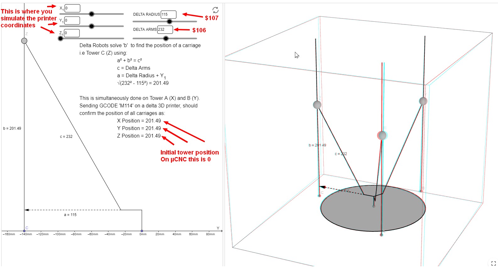
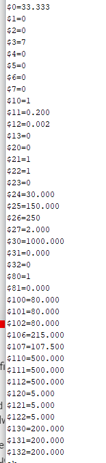
1- input the same 106 and 107 values on the printer and the sim: ok
2- Hini marked at 186.2 for each tower
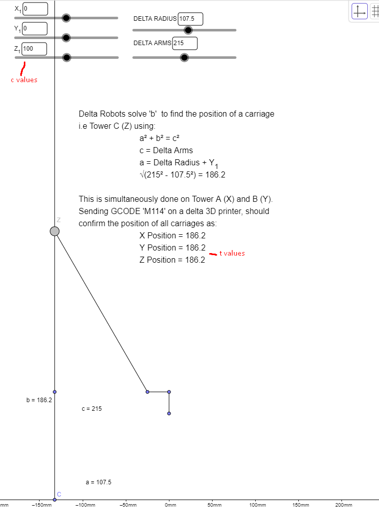
3- moved the printer down with G0Z100 and positioned the sim at +100, the sim measures from the bottom where as the printer from the top atm. this might look weird in the calculations, not sure, ill see.

Xc Yc Zc - “cartesian coordinates” of the nozzle - what we input in Grbl
Xt Yt Zt - “towers coordinates” where the motors (more like the carriage of each tower) find themselves

this would be Xt Yt Zt, which if i move the effector down with a G0Z100 i know they are all 100mm.

i thought id have to measure with a ruler but “??” bring up an Ov:100,100,100 which seems to be the t position of each tower - i can measure both i guess, although it probably not necessary


the sim does not change the position of the tX tY tZ values regardless of where Zc is if Xc and Yc are 0.
i guess i can still measure the difference but should the Zc be the same as Zt? and not 100 vs 186.2
if its just something you didnt not add to geogebra no worries i was just wondering

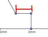
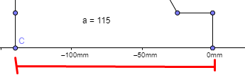
up and down in the (brackets) refers to how to carriage of each tower moved from the previous point in relation to the ground


4- G0X40 sent through - seems like the effector lifted off the plane, anyways values are measured by hand because i cant bring up the Ov values with the ?? as i mentioned before

on the printer the values are: Xt: 115 (down by 15) Yt:74 (up by 26) Zt:96 (up by 4) - measured by hand

on the sim the values are: Xt:201.29 (up by 15.09) Yt: 160.07 (down by 26.13) Zt: 181.85 (down by 4.35)

the numbers are reverse either because there is a difference of the effector direction between printer and sim, G0X40 on my printer send the carriage in the inverse direction of the G0X40 in the sim.

.
btw i believe the current rotation of the overall steppers is almost inline with the stock configuration, X+ and X- face the correct way, but Y+ and Y- are opposed


a G0X-40 should create the opposing effect
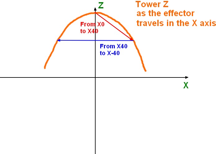
btw when going from G0X40 to G0X-40 the effector moves down and then up again - curved bottom as we said

Anyways in a G0X-40
on the printer the values are: Xt: 74 (up by 26) Yt:115 (down by 15) Zt:96 (up by 4) - measured by hand

on the sim the values are: Xt:160.07 (up by 15.09) Yt: 201.29(down by 26.13) Zt: 181.85 (down by 4.35)

in both cases printer Xt and sim Yt as well as printer Yt and sim Xt are inverted, its the Zt values that are in the wong direction.
If I input a G0X40 on the printer and a G0X-40 on the sim the Xt’s and Yt’s match, and in the inverted scenario too


I didnt catch this at first (bc the printer and sim values are inverted and it was confusing me but:

I saw it from the sim the Zt (compared to the ground surface) went down in both G0X40 and G0X-40, where as on my printer the Zt (compared to the ground surface) it went up (compared to the ground surface) this meant that there is about 4+4mm difference on the Z axis and I believe that mispositioning my effector -

1- ill measure my effector height from my desk/ground surface at G0Z100 (X0 and Y0) - call it “Eini”
2- then ill issue a G0X40 which as we know will move the effector upwards and the Zt 96 rather than 104 which the sim does, Xt and Yt should be correct - ill measure that too as “Eup” to confirm it did not move horizontally
3- ill tape the X and Y tower carriages so they dont move
4- ill switch off the power supply and move the Z carriage down 4+4mm to match the sim height of the Zt (dont know how to move only one tower in grbl)
5- ill measure the distance of the effector from the desk/ground surface once again as “Ex40”, if its the same as “Eini” we can assume the effector would have moved in a planar horizontal plane rather than the current spherical shape it does now if the Zt moved in the opposing direction

1- Eini= 138mm
2- Eup= 148mm
3- taped Xt and Yt
4- moved Zt down 8mm
5-Ex40= 146mm (not 138 :thinking: )

seems like the 8mm on the Zt dont amount for the 10mm offset, in retrospect i dont know how i thought this would have given me those 10mm back given the delta kinematics…

lol

In the midst of this i sent the Zc up too high at some point and it the Y carriage hit its switch stopping the other axis very gracefully and without doing those awful stepper noises, so thats good!


Im trying the printer to sim comparison with a G0Y40 to see if its a Zt thing again or if it the discrepancy will manifest differently

G0Y-40 sent through - G0Y40 on the sim so they match based on effector position

on the printer the values are: Xt: 83.5 (up by 16.5) Yt:83.5 (up by 16.5) Zt:118 (down by 18) - measured by hand

on the sim the values are: Xt:193.31 (up by 7.11) Yt: 193.31 (up by 7.11) Zt: 156.42 (down by 29.8)

well i didnt expect these to be off in all direction…i was expecting to see an opposed value like before

-i was just about done here and ready to go to bed as i was confused, decided to run a G0Y-40 on both even though they effector goes in different directions


G0Y-40 sent through - G0Y-40 on the sim this time

on the printer the values are: Xt: 83.5 (up by 16.5) Yt:83.5 (up by 16.5) Zt:118 (down by 18) - measured by hand

on the sim the values are: Xt:169.61 (down by 16.59 down) Yt: 169.61 (down by 16.59 down) Zt: 204.13 (up by 17.93)

values match exactly considering i measured by hand on the printer, but they go in different directions, no skipped steps


as i mentioned before the Y+ and Y- are in opposing direction compared to the stock, i dont know if this is what could cause this but from what i understand its probably not

i guess its just the arm lengths and radii that are wrong, in that case ill revisit tomorrow for a quintuple check :rofl: aiai, sorry for the ridiculously long post

1 Like

Lol I’m trying to digest your post slowly.

I’ll try to go step by step but a couple of things stand out right way.

You did a G0Z100??? (not G0Z-100???)
G0Z100 should make the motors move the printer up and not down. This is an indication that all steppers are inverted. Check setting $3. If $3=0 change to $3=7. if $3=7 change to $3=0
You also may need to do the same on $23 (homing direction invert mask) the same way.

Positive Z should make the printer go up and negative Z should make the printer go down.

NOTE: Ov:100,100,100 are the overrides rapid feed, normal feed and spindle (not distances)

Yes confirm with a ruler. The output of the WCO is were the machine think it is. Not were it actually is because you don’t have a close feedback system (motors + encoders).

I guess the values presented are relative to the effector and not the base (just a matter of reference I guess). They should apply anyway because we are trying to eval relative motion (from an initial position to the next) and not absolute.

If the total distance matches between the sim and the real displacement on your printer good. That is enough for me to know that no steps are being missed in any form. :+1: Steps can be missed in several ways. If you exceed the driver or motor capabilities you will ear and see the motor jamming and making noise (high pitch). But if the step signal is somehow unrecognized by the driver you wont notice anything besides not running the distance it should. This should not happen on µCNC since the generated step signal is simetrical for (ton and toff)…but just to make sure I asked you to check it out.

Let’s see if fixing the direction on the steppers also takes care of that inversion. Maybe your mesurments are correct after all.

1 Like

Back on it and there are new weird behaviours :sweat_smile:

changed the masks, they were 0 for both $3 aand $23, now theyre both 7.

saved to eeprom, restarted it, unlocked and homed. all motors go up towards the switches, homes nicely. I tried a G0Z-10 and the X axis moved up and hit the end stop…weird
i close the serial monitor, reopen it, unlock and home, G0Y-10 and again same thing, X axis goes up, hits the switch…
Tried it again with a G0X-10 and again X axis up and hit the switch. Tried other values, positive, negative, different axis, only X went up.

So i turned of the psu, moved the effector down about half way, and tried again without the homing, G0Z10 send the effector up, all axis moved fine, G0X10 etc… I homed the machine after this and the X axis going up thing happened again lol

so thats weird no.1

weird no.2, which might be a $106 and $107 thing
is that when i had the effector about half way down, I did some G0X0 to G0X40 to G0X-40 movements.
G0X0 to G0X40 lifts off of the plane about 2mm, much less than the 8mm we saw before. G0X40 to G0X-40 ends up at the same height which is good, but during the travel the effector, as is travelling past the G0X0 position, drops below the G0X0 for about 4mm, so about 6mm down and then up again… and if i go from G0X-40 to G0X0 again its only a 2mm drop

this also happens with G0Y movements

Y+ and Y- directions seem to be inline with the stock printer now. But X is inverted. - i thought i could fix this by setting $2=1 or $2=6 but neither worked, i dont think i really understand $2 – Step port invert, mask.
perplexed as usual hahah

also by homing seek is set to $24=50, thats 50mm/min correct? its so slow its almost funny

1 Like

LOL

I’ll investigate that one. That is weird. Maybe a bug?? I’ll keep you posted.

What are the values of $106 and $107 you’re using now?

$2 is to invert the logic on the step pulse pins because some drivers step the motor on high-to-low transition and others the other way around and the dir pin may not be updated correctly. I believe in the case of Grbl and µCNC this is irrelevant for most drivers (don’t know of any particular case). Most cases keep this at 0.

If you want to invert the dir of a stepper always use $3. Each motor is a bit of this number.
Bit 0 is related to STEPPER0 that in your case is related to AXIS X and so on.

Translating into simple terms it’s a bit mask like in this table

|BIT  |       7      |      6       |5|4|3|2|1|0|
|AXIS |Z2 or Y2 or X2|Z2 or Y2 or X2|C|B|A|Z|Y|X|

To invert X, Y and Z you set bits 0, 1 and 2 to 1. That yelds the binary mask 00000111 that is equivalent to 7 (like the config I told you to use)

|AXIS     |Z2 or Y2 or X2|Z2 or Y2 or X2|C|B|A|Z|Y|X|
|BIT VALUE|       0      |      0       |0|0|0|1|1|1|

If you want to revert back only the X axis set bit0 to 0 again (00000110=6)
This works this way for all the other settings that use a bit mask (like limit switches, homing direction and even invert step pulse)

|$24|Homing feed, mm/min|
|$25|Homing seek, mm/min|

You can increase these If you want. Limit switch are working fine so catastrophic collisions should not happen. The slower speed ($24) is just to increase the repeatability in the homing position. If you’re not very worried about this parameter you can increase it to match $25.

EDIT: About the weirdness…Sometimes I surprise myself (and not in a good way :triumph:). While chasing that bug in AVR boards, I introduced another stupid bug. lolol. This one might even be the explanation for the non planar motions on your delta. As soon as I patch your branch (and main branch also) I’ll let you know.

1 Like

Ah I see now about $2. I was reading the grbl commands doc on github and i noticed $106 and $107 are not there, obviously cartesian machines would not need them, but I wonder if its a hidden command or if you coded it. The thing is when using a $3=1 or $3=6 inverting either the X or the Y and Z im inverting the direction of the tower such as Xt Yt and Zt, rather than the direction of the effector what I was previously calling Xc Yc and Zc.
With the current commands I dont see how to invert the cartiesian direction of the X, flipping X and X- without flipping the tower one which results in confusion as I try to home and the Y and Z towers go up but X goes down.

Wouldn’t the printer home most of the way at a faster speed, hit the switches, and then repeat it to ensure the correct positioning at a slower speed? Ive hit the switches at 500mm/min which is my movement speed and everything behaved fine, I might just bump $24 a bit.

:100:

1 Like

Lunch break is over. I only had time to patch your branch without running any test file.

Now this will change the behavior of the machine a bit and the settings need to be tested so before anything. Follow these steps:

  1. Download bastardazzo branch, compile and upload.
  2. Send $$ and check the settings (they should be untouched but just to make sure).
  3. Set $3=0 and $23=7 (don’t need to send $SS yet)
  4. Unlock the printer with $X
  5. Send a small motion command like G0Z1. Did all steppers moved up? If no, then you need to apply the correct mask to $3.
  6. Before homing put a finger on the power supply switch. I believe $23=7 will make all motors go up as expected (right now I’m not home and I have no way of checking this myself). If they start going down turn the printer of to avoid crashing in the bed.
  7. If everything is going the right direction then do a $SS to store the settings

I’ll be able to properly test those steps I just told when I get home in a few hours, but if you get to test this before follow these steps.

Although µCNC protocol relies on Grbl’s protocol, µCNC was coded from scratch. $106 and $107 (and other settings like PID controllers or those extra commands like $SS, $P, etc), don’t exist in the original Grbl command list. In the case of $106 and $107 they only are activated if a DELTA kinematics is used.
I haven’t updated the wiki yet but I will soon to add this bit of info as soon as i get version 1.4 in a more “polished” state.

That was all because of that stupid bug I let pass through. :sweat_smile:

In that case bump up $25. $25 is the fast homing rate. After hit the switches it will repeat with the slow homing rate ($24). Just do the steps I stated earlier first.

EDIT: I’ve updated the µCNC basic guide wiki page with additional configuration settings that exist (if enabled by config). I never really though about it but a lot of settings were not explained and some of those features exist in µCNC way back like skew compensation and backlash compensation.

1 Like

Steps 1-7 completed, only different is the $3=7 mask is the correct one in this case
Everything moved fine, no issues, no crashing and $24=30 and $25=150 seem to work well for these tests, ill check for repeatability and fine tuning later!

Unfortunately i get the same issue as before where after setting $3=7 and home the machine, any movement after that will result in only the X axis moving up and hitting the switch.

So if I set the $3=0 which doesnt result in the X axis bug, i also have to set $23=0.
at $3=0 and $23=0 the homing works fine, X- and X+ are in the correct direction based on stock config, Y axis is flipped.

I tried some movement at G0Z100 and then G0X40 and G0Y40 and the lift off seems to be even more than before, about 8mm isntead of 6mm, always in the up direction compared to the ground.

I was curious to see what would happen if i homed on $3=0, $23=0, do a G0Z100 to drop it midway and then changed $3=7 (introducing the bug). I sent a G0Z10 and all axis began to drop, almost like a homing sequence, they went about 100mm down before I turned the macine off now to crash it

Out of more curiosity, I tried it again. Settings above, process like before $3=0, $23=0, do a G0Z100 to drop it midway and then changed $3=7. I then tried a G0Y40 and the distance of the effector went from 148mm (G0Y0) to 148mm after the G0Y40, planar?! Not exactly… almost though
The start and end positions of the effector are good, but in between it dips about 1.5mm, this might be due to the $106 $107 values though.

Ran G0X40, G0X0 and G0X-40 and same thing, only about 1.5mm of lift between them.

Then I ran G0Z10 and realised that its based on the soft limit of 200, so it dropped down to 10mm the 200 based on the homing from before. - this might be wrong, i close the serial monitor so it might have stopped bc of that, even though it usually stops after closing and reopening it.

I tried again but set $3 and $23 to 7, homed, this again introduces that bug where X axis acts as reads all axis movement as X and both + and - directions as going up.

:thinking: :frowning:

1 Like

As I told you I did not had much time to do tests. Give me 1 or 2 days to check that out.
I’ll try to reproduce your steps and check that out. I never tested like that of reverting the setting midway.

The confusing aspect of this thing is that the simulation steps and calculations seem to mach but the motion on your machine tells another story.
I starting to thing I will only be able to pull this one out if I get my hands or build myself a delta. :confused:

Yeah no worries I understand, Its just i feel like I cant contribute much unfortunately
Would it make sense for you to try to use my printer from a distance? Might be a longshot but maybe we could set that up

1 Like

Thanks for the offer. First let me run all the tests and try to spot anything on my side.
I won’t need direct control over your printer.
If it comes to that we might try meet via Zoom and try to figure out a couple of things that way. Going though the settings and seeing your machine move might aid in getting some clues on to whats going on.

1 Like

Sounds good, lmk!

I’ve managed to reproduce the behavior you said I think. I’ll investigate. Something goes crazy after homing.

Can you run a test for me?

  1. Just position the pen on the paper by hand with the printer off and then turn the printer on.
  2. DO NOT HOME. Just unlock the printer with a $X.
  3. try the G0X40 and G0X-40 commands. If you still get a lift try inserting the measures you took previously $106=245 $107=106 save and repeat the procedure from step 1

EDIT: I’ve modified the homing motion for the delta but it’s late and I have to hit bed. No point in trying out my commit since I still have to proper test this.
This is what the new homing will do.
Setting $3 will have to be in a way that with G0Z must go up
Setting $23 will have to have bit 2 (Z axis) set (value 7 will do just fine) to make all axis seek home in the positive Z(up) direction
After homing the print will say that X and Y are the middle (relative to the max travel for each axis) and Z at the max height to match the real position.

This has the added bonus of being able to enable the soft limit setting that will prevent the machine to travel where is not suppost by checking the command coordinates against a virtual bounding box.

Tomorrow I’ll test this and try to see how it acts from that point on.
I’ve also found a bug that did not affect motion but caused motors (almost all of them at least) to always be locked/enable. This was fixed. Motors will only lock after unlock the printer or start the first motion.

EDIT2: Just a quick update on what I’ve been trying. I think I know what’s going on and I’m thinking how I’ll tackle this one.

Can you run a test for me to see if the results I’m having match the real motion? Same test as before but like this.

  1. Just position the pen on the paper by hand with the printer off and then turn the printer on.
  2. DO NOT HOME. Just unlock the printer with a $X.
  3. Send a G91 to put the printer in relative coordinates.
  4. Send G0X1 command 40 times. This will make the printer go to X40 1mm at time
  5. Send G0X-1 command 80 times. This will make the printer go to X-40 1mm at time

Was there lift?
By the way try this with the current bastardazzo branch that I updated.

1 Like

OK on it again. Got the updated branch

To ensure the effector is level ill upload the new firmware, then home it, then drop it to about 170mm so the pen can sit close to effector and touch the paper. Load the pen, restart the Mega and restart the serial monitor and then continue as you described. - This didnt work, $3=7 still has that X axis bug, so i just lowered it by hand.

I marked the pen with some tape to be able to notice if the effector went down rather than up.
Over the 40x G0X1 the effector went down about 1.5mm total.
Halfway through the G0X-1, the effector went up 1.5mm, at the G0X-40 the effector is up 3mm total.

Did a G0X-40 to G0X40 to check if its consistent. Effector went down by 3mm total during this move.

Tried a G0X-40 in one go out of curiosity. from position X40 to X0 the effector seemed to travel mostly planar for about 2/3 of the way, then at the last third it lifted 1.5mm (lift was linear in the incremental G0X1/G0X-1 commands).

From X0 to X-40 it lifted again about 1.5mm. 3mm total over X40 to X-40.

I just noticed that it actualy dips about .5mm before going up 1.5mm on those previous moves.

Tried a G0X80 (from X-40 to X40), it dipped about 3mm as it reached the centre and then then lifted about 3mm as it got to X40.

I then did a G0X-40 to get it to X0 and it lifted 1.5mm.

Tried with Y: quite similar.

from Y40 to Y0 (G0Y-40) it lifts 1.5mm, from Y0 to Y-40 (G0Y-40 again) it lifts 1.5mm again.

but from Y40 to Y-40 (G0Y-80) it dips first and then goes back up.
Whats odd is that in the end position after the G0Y-80 (Y40 to Y-40) the distance effector-bed is about 6mm, instead on the opposite move G0Y80 (Y-40 to Y40), the end position of the effector is only about 3mm from the bed, weird that theyre not equal…(might be a mistake on my part - later checked three times over and its the printer doing it, not a mistake)

Tried this on Y and Its the same as for X.
-From Y40 to Y-40 in increments there is a linear upward movement of the effector. 3mm total over the distance.

-From Y40 to Y-40 with a G0X-80 command there is a dip of about 3mm until the middle and then the lift of 6mm. Going the opposite way dips 6mm first till the middle and then lifts 3mm.

-From Y-40 to Y0 with a G0X40 command there is a dip of about 3mm until half way through and then the lift of 1.5mm by the time its at Y0. Going the opposite is -1.5 and + 3.

–From Y0 to Y40 with a G0X40 command there is a dip of about 3mm until half way through and then the lift of 1.5mm by the time its at Y40. Its not mirrored on the centre of the printbed but rather repeated.

Exactly the same happens on X axis. As the effector moves towards the + of X or Y axis in increments of 40mm it loses 1.5mm each time.
In -X and Y- directions it lifts more than it dips - in increments it lifts overall

I tried a G0X-160 from X80 to X-80 and the movement is again dip and then lift, dip is smaller than the lift. The pen tip at X-80 was about 23mm up away from the bed.

In retrospect it dont believe that the 1mm increment moves are linear, its just that within that 1mm it dips a bit and then lifts a bit more than the dip, over 80mm it just looks linear, but it must be that same curved rather than planar movement

Tried with $106=245 and $107=106 and the same happened.
In incremental moves f 1mm, over 40mm distance the final lift seems to be about 1.5mm again.

I think there are multiple things happening that are causing the issues.

1st problem
I initially though this was simpler than it is. I treated the delta kinematic as I treated cartesian or coreXY.
I calculate a target coordinate, convert the new position to step coordinates and do a linear motion to that position. The delta has a lot more than that going on.
Let’s look at the Z tower as an example:
If you look to your printer from above you will have something like this:

Your tower Z is inline with the Y axis so lets take that one has an example. If we rotate that view 90º and stare directly to the Z tower we will see this:

The orange line is the relative height of the Z tower to the effector as the effector travels parallel to the X axis. The tower will be at the highest point when X is 0 and than the curve describe a non rectilinear movement (I have not made the math but I believe the curve described is either a sin or a x^2 kind of curve).
Currently when you start from X0 and do a G0X40 the firmware makes a linear motion from X0 to X40 (red line) as you can see that represents a distortion in the ideal travel curve. It will make to it’s destination but in a straight line (this will result in a non rectilinear motion of the effector).

Worst when you do a G0X-40 from X40 the calculated height for the Z tower is the same. So the Z tower will stand still, when in reality it should go up and then down with a non linear speed.

This will cause the effector to move in a non rectilinear way although we ordered it to travel in a straight line.

One way It comes to my mind to fix this is by treating linear motions in the delta the same way it is done with arc commands…breaking down into shorter line segments. The penalty of this is that more calculation loops have to be done and this will impact on the speed of the printer.

2nd problem
I’ve done the exercise of converting the coordinates from 3D points to Z tower height several times and they do seem to match. But sometimes the calculated steps go completely wild. After moving the machine a bit G0X0Y0Z0 should match stepper position (0,0,0) and it doesn’t. I’m trying to track down that problem in particular. And I’ll let you know on that. I think this is related to the calculation of the forward kinematic that is figuring the incorrect position back (I’m getting these results in the negative coordinate regions)

There may be a 3th problem that is the parameters are not correct and are causing also distortions (curves in the motion). But first I have to rule the other 2 first.

I have the felling I’m trying to re-invent the wheel here but all the papers I found only explained the kinematic computations and I don’t recall ever reading a part about these motion details.

1 Like