I’m not sure of your terms or what you are doing. By “hard stops” does that mean something you’ve installed near the ends of the tubing to block the trucks, or does that mean pushing the core against the trucks? By deflection are you referring to how the axis naturally aligns or have you measured the diagonals on the machine? This is a Burly and you posted here awhile ago, so I assume the machine is running?
To clarify my question with common terms this is from the FAQ:
"Getting it as square as possible –
-Before you start your cut on the MPCNC, measure each roller to its closest corner block, take the same measurement on its counterpart. You should be able to tweak these by hand to get all axis equal to its counterpart at the same time before you start your cut. Once you start your cut they are locked in place. Dual endstops can do this for you with the cost being more CAM planning. If you can’t get them set well enough see the next FAQ."
So in those terms the question would be:
Is 4mm difference in roller to corner distance between counterparts too much to correct with this method?
If so what is the maximum difference between counterpart measurements you should attempt to correct with this method?
I though this might be what you were talking about, and no, correcting 4mm this way is not an issue. In fact I can move the trucks on my machine centimeters independently.
My confusion here is with your term “hard stops” since If I remember correctly, there was no official stop block for the Burly. And the FAQ you reference is not talking about hard stops. If you are concerned about squaring (not really necessary for a lot of milling), then you want an adjustable stop block on both end of each axis near the origin of the machine. A hose clamp might work, but I think there are clamps on Thingiverse that would work. Start with these blocks equal distant from the end of the machine, and power up the machine with the axes pushed against the stops. With a pen plotting tool installed, draw a big square. Measure the diagonals of the square and adjust the stop blocks and repeat until the diagonals are equal.
I suppose the amount of correction that is OK without over stressing the parts would depend on the length of the axis. My build is small compared to some so moving 4mm at the end of a 600mm axis would require more force and stress than 4mm on a 1200mm axis!
As there is no stock size for the MPCNC I guess you have to be careful when reading advice as the advice might need to be scaled for your build size.
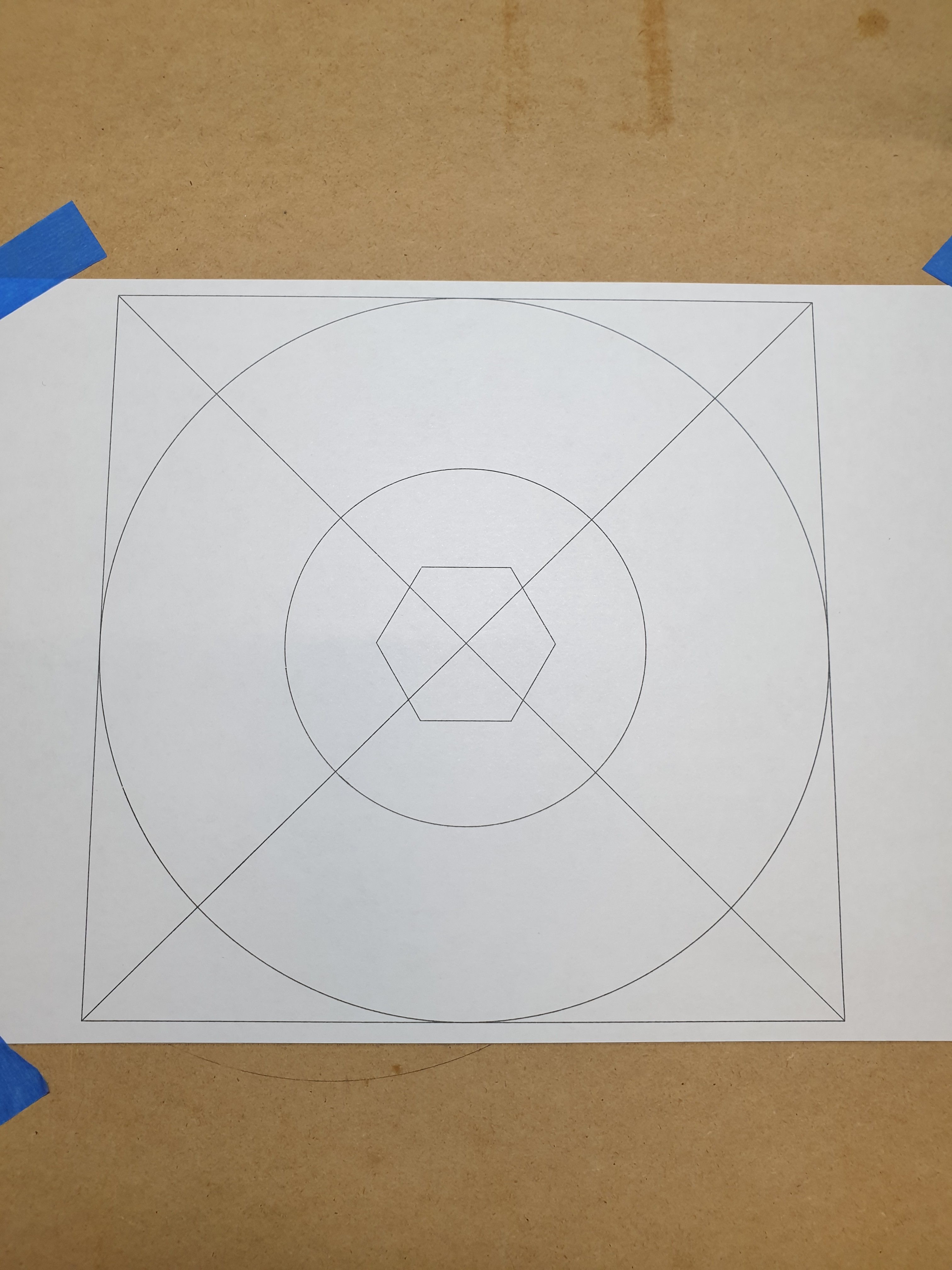
I did get to the point of first moves and pen plotting.
Got a nice crown and did some accuracy testing like you suggested.
It showed I was out of square but I was able to correct it by forcing the axis into square as discussed. I just wanted to know if doing this was likely to damage printed parts.
I decided to use it as is for a while before trying to diagnose the underlying square issues.
My working area XY is roughly 790 mm x 660mm. With the trucks in the middle of the pipes, I could easily slide the trucks on one side of the machine independently of the other. I just went out and checked the short axis, and I can slide my trucks around 10mm in each direction before I have any serious resistance. My machine is a Primo, but this movement feels about like what I could do with my Burly.
forcing the axis into square
Your concern for you 3D printing parts and using the word “forcing” makes me wonder if something else is going on here…like perhaps you have your belts too tight, or a bow in your tubing. What size is your machine? Place an axis in the middle of the tubing, then push one truck back and forth. How far can you move it easily? Now try the same thing at the ends of your tubing. Does it require significantly more force? Strum your belts. This is a note from the instructions for the Primo build, but it also applies to the Burly build:
The needed tension is much less than most people think. It should just barely make a noise when plucked.
Thanks again for your input It’s really appreciated.
Build size Work area = 344mm x 344mm x 77mm
I think you may have a point with belt tension.
Can’t check at the minute as I dismantled the Gantry and Z Axis this afternoon. Base rails were slightly out of square (only 3mm out on diagonals) but wanted to sort that out. Now within a fraction of mm on corner to corner diagonals - much happier with that.
Had a tiny amount of rocking on Z tubes when hung over edge of table so sorted that too.
I’ll put everything back together hopefully tomorrow with lighter belt tension and see where I’m at.
The good thing is the more I take it apart and put it back together again the more I feel I understand the design and how the parts interact. Famous last words…
Definitely more confident of my build now than I was a week ago.