Open the gcode file in a text editor, and you can see the Z values for the cut. Measure your current depth and give yourself a little freedom. You can cut out a bunch of the middle of the file.
The hard parts depends if you originally homed first.
Open the gcode file in a text editor, and you can see the Z values for the cut. Measure your current depth and give yourself a little freedom. You can cut out a bunch of the middle of the file.
The hard parts depends if you originally homed first.
Am I supposed to home it first, or do I keep the bit at where it left off?
If you originally homed it and then ran your file from there, you can do the same. You would basically just start your file again but it would skip over the chunk you deleted in notepad.
Otherwise you have no idea where the exact position of your bit actually is and there is not a way to resume it. You can not resume from your current position since that is unknown.
It depends on your CAM software.
Estlcam puts in comments (Hole 1, drill 3, part 3) for each of the shapes that it cuts through in 2D or 2,5D mode. If you’re carving from an STL, I’m less sure how that goes.
In the original project, each cut line is identified in the same way that it’s commented in the result, so you can see that (for example) it usually cuts all of the holes in something approaching a sensible order, and cuts the shape outline last. you can override this, but I usually see no reason to do that.
So to prepare, you need to get the machine to the same 0 point at it was originally. For me, this means home the machine, jog to a certain set of coordinates (I usually write them in pencil on the work piece, but that won’t work for steel, I guess.) and then run my macro which makes that point zero. Probe for Z and then start.
Now I look at my Estlcam project file and relate which cut it’s on. Say hole 10. I can then go into the Gcode file and remove everything before hole #10. If I wanted to get fancy, I could remove the passes before the current depth, but this is generally close enough for my re-starts.
The tricky bit is making sure that I don’t mar the work when the cut starts, so I add some start code. the first part of each cut in Estlcam will move to the start of each cut at the clearance plane, then plunge, so I leave the general start code, and then add in a line to lift Z to the clearance plane at least. the rest can run from there. If I were to start the cut part way through at a depth layer, then I would also add a line to move to the X/Y coordinates of the plunge as well, otherwise, it will go straight there, probably cutting into something you didn’t want and/or breaking your endmill.
New problem - Core Clamps crack after a while.
Is there a better material other than PLA or better infill or something, so it can sustain the vibrations from the router?
Thank you
They shouldn’t. I have not cracked one yet. You can change material but that will make the machine less rigid.
I would guess overtightening, or CAM making excessive vibrations (usually from hitting something unexpected or crashing the core).
Hitting something like steel??? Sorry…couldn’t help it. I also have never had one crack. But I do print everything with PLA+ Not sure what difference that makes if any.
What are your cut specs as compared to my latest video. You should be able to take a bigger bite than I have. LR3 Steel test - YouTube
In general, regardless of what you crash into, the motors skip steps before any parts crack. Maybe certain frequencies of vibration can stress the parts without putting stress on the motors, but that seems unlikely.
Remember that tighter is not stiffer, which is a common misconception.
If a spring has a certain spring constant k that represents force per displacement dF/dx, then increasing displacement increases force, but the stiffness is not changed. It does have to be tight enough that the bearings don’t lift off the rails under load, or in the case of belts, it must not go slack on one side, but as long as you have good contact, tighter is not better.
Curious how they crack, along or through layer lines? If along layer lines, have you already tweaked temp, flow, overlap, layer height and other settings to maximize part adhesion/strength? Cracking part pics appreciated ![]()
For me, for some reason matte PLA delaminates more easily than regular PLA, yet others say silky PLA causes them more problems ![]()
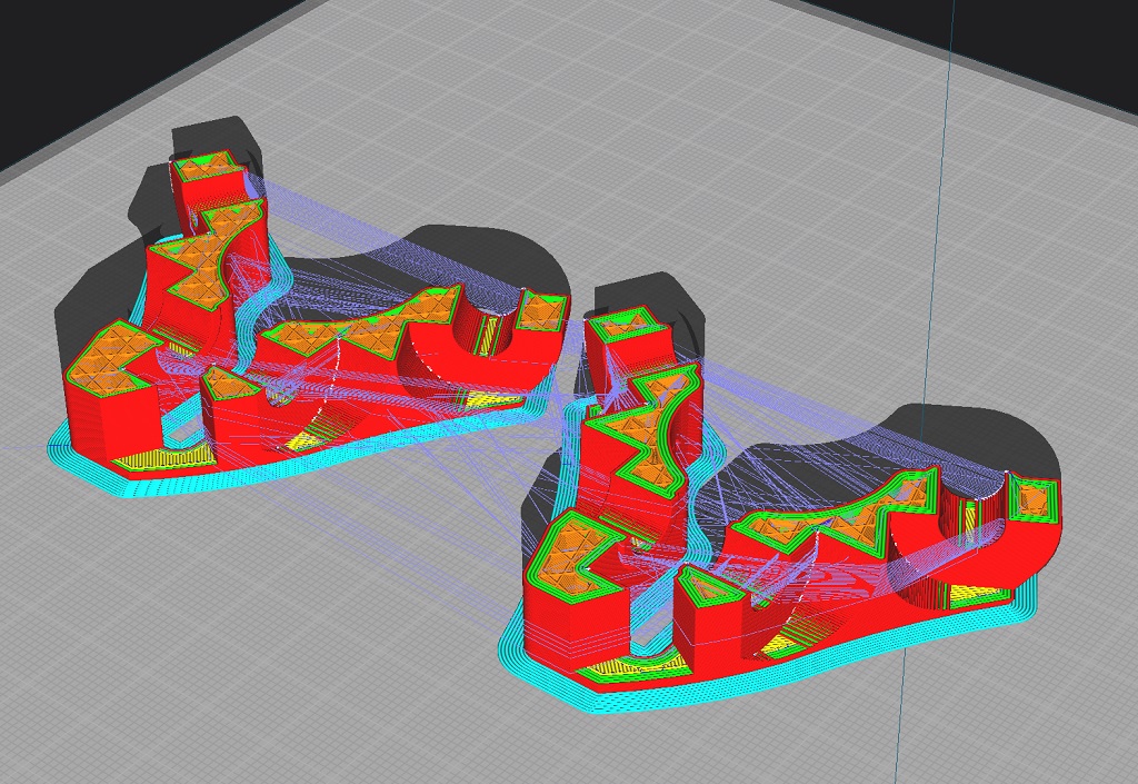
There’s some free online gcode viewers that’ll help you visually figure out which lines are doing what cuts. helpful for figuring out what to remove if trying to recover. I think https://ncviewer.com is one of them. Good luck!
I meant it more in the “whoops I hit something” and it jumps and kicks back real nasty kinda vibrations way. A subtle mistake will skip a step, a real whoopsie can crank on things in an unexpected way.
Any silk PLA I’ve used is ridiculously weaker than regular PLA, I don’t know why.
How about more walls and tops/bottoms? From my experience, generally adding walls and top/bottom layers does far more to increase strength vs infill. This is also supported by the science of structural engineering… because walls/tops/bottoms actually form the shell of a monocoque structure (hollow thin shell structure pretty much).
When I was slicing my first parts for my primo, I played with these settings and observed what happens to the resulting layers around critical stress areas (bolt holes, etc). With the slicer preview, you can imagine how much stronger the 4wall part might be. It takes more time and filament, but I think worth it especially if you find standard prints too weak.
CarbonX petg-cf or pla-cf are my choices for high stress parts. It’s in it’s own league as far as strength (and unfortunately price). It’s just one of those things you have to try to see what’s up. I used to break clamps with some frequency on my primo… haven’t broken a 4-wall carbonX clamp yet… and if you’ve seen my rig or some of the projects it’s done… that says a lot.
The parts as designed and tested will already deform Stainless steel tubes. The only issue comes in from overtightening them and cracking as far as I can tell.
This has not proven to be a major concern since this was release.
My question, what will the oil do to pla after a while? That might be why it broke.
Interesting, internets sayz certain types of oil will effect PLA.
Also, adhesion seems to drop off with layer heights > 50% of nozzle width.

Haven’t done any testing, but am happy with my 0.6mm nozzle parts with 0.32mm layer height seem strong enough. Using Cura 5.0+, so slicer will vary layer width (impacting adhesion/strength) to an extent for model accuracy.
Would be interesting/insightful to see the cracks, especially if they’re happening in the same location, and maybe a look at the slicer view to understand what was extruded in those region(s).
I have watched that one a few times, I didn’t remember the 50% thing (although he did not test it on bigger nozzles. I think I need to lower my layer heights a bit now. I am at 70% ratio.
So layer height, infill density, wall thickness, temps, speeds, cooling. I need to watch the whole series again and get the “CNC Kitchen Ideal” and test a real world part of mine to see how it does as compared to how I print them now.
damn, we should have picked his mind at rmrrf.