MadMachine - let the fun begin

Hi Bill

I agree that what is jokingly referred to as “cooling” on Alison leaves a lot to be desired!!!

Over the last few day I have managed to figure out that she is made up from parts of no less that 4 DIFFERENT makes of I3 clones - and in the beginning nothing matched anything else.

I have sorted most of that out but the journey continues because many of the parts used were worn out or faulty to start with.

For example, yesterday I was trying something prior to a test print so I switched on the extruder heater just to get a bit of heat into it - set it to 130 degrees.

BUT filament came oozing out!!!

So now I must have a look at the heat sensor - its probably under-reading and needs replacement and / or re-calibration.

That may explain why the Teflon tube needs replacing so often and why filament gets carbonized so easily.

I also had a look at the nozzle orifice under a microscope earlier today - what a mess!!

The orifice is bell-mouthed, it is showing definite wear patterns - and I cannot find a new replacement locally - out of stock!!!

They have 0.3mm and 0.6mm ones but one place had an old 0.4mm one that they tell me is still serviceable so I’m going to use that to see whats going on and if things improve.

I also bought a Volcano style heater block and .4, .6, .8 and 1mm nozzles to try out.

They did not have thermistors unfortunately…

The thing is that once I have done the parts for my MPCNC the main use for the 3D printer will be to prototype the components that will run on the mill to check aesthetics and fit before milling them and the finish / layer height is not really a priority there.

But the engineer in me needs to get her working correctly - so we will be doing that…

Thanks for the feedback.

Aubrey

The extruder is the “normal” one, I have replaced the M6 “heat-break” threaded tube and am forever replacing the Teflon liner.

I bought 2 new fans yesterday.

I cant get exact dimensional matches locally - seems like the ones they had in the scrap pile when they put her together are a bit “non-standard” so I’ll have to print new fan ducting etc.

Remember that I have not got a Bowden style setup, the whole melt tube/hearer assembly fits directly into the bottom of the extruder gear housing and there is a lock nut that you need to be able to get to so a cooling fin piece simply will not fit in the space available.

The fancy looking (and by all accounts, very efficient) aluminium finned cooling tower thingie is standard on Bowdens and the “old school” types simply rely on cooling the tube - not very efficient but still.

My initial thought on the Bowden style setup is a bit mixed.

On the one hand the stepper is not having to be moved around which makes things easier on the machine but on the other hand I think that accurate control of the filament feed is somewhat compromised due to the clearance between the Bowden tube and the filament.

Maybe it is a case of deciding which method has the least disadvantages.

Hi Lionel

Thanks very much for the offer - I may just take you up on it!!!

At this point I am not quite ready to start actual construction - still need motors and the other things and you know just how darn expensive they are here!

I used to be in Roodepoort but I’m now in Kraaifontein (CPT) for almost 2 years now.

I run a boarding house so space is VERY restricted but a dear friend has offered me the use of a 3M x 3M Wendy house - that I need to reinforce the floor on before I can actually move my studio / workshop into it - busy with that right now…

I know that everything takes time but "my hol begin juk"as they say locally ;>}

(Means something like “got ants in my pants” for those that don’t understand Afrikaans)

All the best

Aubrey

It may be just because I’m not finding a good picture of your hot end, showing the cooling arrangement for the top half of the throat. The 6mm threaded shaft that screws into the heating block and often has a PTFE liner is the throat. It should be screwed into the heating block at the bottom and have a finned heatsink that screws into the top half. The cooling fan runs all the time and blows on the finned heatsink. There is often a lower fan that blows on the workpiece but that’s software controlled to only run when extra cooling is needed to keep the extruded filament from slumping.

The impression I have is that yours is either missing the finned heatsink and just has a fan blowing on the throat or the heatsink isn’t giving you good contact so the cooling isn’t being transferred well.

If you are using a MK8 style extruder/hot end (https://www.geeetech.com/wiki/index.php/MK8_Extruder) there should be a heat sink that actually is being used to cool the aluminum that the upper portion of the throat is screwed into. If you leave that heatsink off and just mount the fan directly you won’t get proper cooling and you’ll find yourself melting the PTFE liner. Also, the thermistor that sits slightly inside the hot end should have some thermal grease around it, the same stuff you use between processors and heatsinks. That will give you a more accurate reading then if it’s just stuffed in the hole.

1 Like

With regard to the MK8 Extruder, Ryan wrote this page about how he prepares them https://www.v1engineering.com/import-extruder/

“Assembly of my all metal version of the Mk8 import extruder” (unfortunately, the format is KO , but still readable). You should be able to see how the upper part is cooled with the radiator to avoid heatcreep.


1 Like

Well, just let me know if you need the items printing. I am quite entertained by your adventures with Allison so will keep coming back for my “Fix”.

Should you wish I can also provide you with my contact details just in case you decide to take me up on the offer and I don’t notice.

Otherwise, keep cracking away at it… surely eventually Allison will have to play ball.

1 Like

Hi Bill

The heat-sink was not even there when I got her!!!

One of the first things I bought was 1 meter of Teflon - I have less than 500mm left !!!

[attachment file=57060]

The fan was bolted (only 1 bolt) onto where the heat-sink should have been.

After a bunch of tube blockages (and associated Teflon tube destruction’s) I made an adapter plate to move the fan down so that at least some air was cooling the tube.

That made a big improvement…

What I have got now is this:

[attachment file=57061]

It is still pretty incomplete in the photo but I am getting there.

I went for the “Volcano” style setup because at some point I will be prototyping the works that are going to be run on the MPCNC (in miniature) to check dimensional aesthetics etc and that will probably be done using a 0.5mm or thicker layer height - for those I will not be too concerned about “smoothness” ;>}

And of course there are no 0.4mm nozzles of either style available in Cape Town - so I got 0.6 , 0.8 , and 1.0mm nozzles and for the time being I will use the 0.6 nozzle - it “should” work for printing the components.

You will also notice in the pic that the carrier is now white PLA.

This is a prototype and I had to do much Dremel work to get it working…

When Joseph Prusa designed the original concept something must have gotten lost or twisted in translation because the center to center of the 2 horizontal guide rods is neither metric NOR imperial - it is some seemingly random measurement and I had to slot all sorts of holes to get the alignment correct. (I assumed incorrectly that they would be metric).

New model coming as soon as I can figure out how to use Fusion 360.

The last CAD package I used was back in the days of DOS 3.2 so wish me luck with modeling new parts successfully please!!!

Actually I am thinking of making the rod center to center a full metric measurement and redoing the 2 Z axis parts and the extruder carrier using the “normalized” dimensions.

Maybe at the same time I should move the tube cooling fan to the far right of the stepper and make a duct under the stepper to cool the tube. That way the fan will not be recycling heated air from around all the hot components. It should help a bit and every bit counts in my opinion.

Ambient air temperature here where I am is more often than not between 28 and 33 degrees Celsius and that also probably does not help matters.

And maybe I will get a custom finned tube cooler made - thinking of having it threaded so that I can do away with the lock nut that is currently locking the tube into place - getting to THAT lock nut is a pain!!!

Thanks for your input, every little bit counts!

Aubrey

If you’re going to go to the trouble of reprinting those parts, why not pick one of the open source options, like Prusa’s: https://www.prusa3d.com/prusa-i3-printable-parts/ No CAD required. Just a thought. I love Allison’s tale and am always waiting for the next installment with some amount of anticipation.

1 Like

Hi there thefsreader

That is the design I got with Alison but some things do not make sense to me on it.

Why are they allowing the heat to travel up the tube all the way into the block that the tube is mounted on?

Once the heat has moved beyond the “heat-break” section it should be dissipated as quickly as possible, not so?

The mount block should ALWAYS be at ambient temperature!!!

As should at least the majority or the tube.

Which means that the tube above the heat-break should be ambient for the most part as well - which means no overheating of the entire length of the Teflon tube.

The way that they are doing it does not make a whole lot of sense now does it?

However you can also look at it this way:

By allowing the tube to be heated you are effectively pre-heating the filament.

Why do you need this to happen?

Because the melt chamber on the “short nozzle” design is actually pretty small and by pre-heating the filament it can actually become fully melted more quickly in the small melt chamber.

Problem Solved!!!

Or is it???

I discovered that when I home her, if the extruder heater is on, it STAYS ON until the homing is done - and plastic starts pouring out the nozzle, sometimes smoking if Z is at 180mm or around there.

So I have gotten into the habit of turning extruder heating off before homing - just in case.

And if I forget I manually force the filament down just to provide some cooling inside there.

And this seems to help prevent runaway temperatures.

Maybe I should climb into the settings of firmware and set the heater off before starting the home sequence - will have to see.

In my previous post I mentioned that I have changed to the “Volcano” style nozzle design to get a larger “melt zone” but when I got the new heater block it was aluminium !! ??

So after thinking a bit I came up with the following:

Lead being far more dense than aluminium will store far more heat.

So why use aluminium? And found this - (don’t ask me about what the units of measure are all about, just know that the higher the figure, the faster heat moves through the material)

[attachment file=57066]

So, heat moves through aluminium far quicker than it does through lead.

That means that in lead it takes longer for the thermistor to switch off being the other side of the “melt chamber” in both designs.

BUT the temperature around the heater in the lead unit will of course be much higher than on the aluminium one because the heat moves faster in aluminium than in lead.

BUT because lead is also much denser the amount of heat is far greater and this heat then travels to the melt chamber and keeps on heating the plastic.

The result is that the melt is overheated!!! Which leads to all sorts of problems.

Now with the aluminium heater block the following happens:

  • The thermistor switches off far quicker because the heat gets there faster.
  • There is far less latent heat in the aluminium block (lower density) so the upwards "thermal spike" created by this excess heat being pumped into the block while waiting for the thermistor to be triggered will not be as severe.
  • Because the "melt chamber" volume is far greater, the melt temperature should not spike above acceptable levels and therefor it won't burn or carbonize.
  • When filament is processed thereby reducing the heat in the system the thermistor will turn on again far quicker (aluminium = faster heat/cold traveling through it)
  • And when the heater gets turned back on, the heat will get to the melt chamber far quicker thereby stopping the downward "thermal spike".
The result should be better and tighter control over the temperature of the material being extruded which can only lead to better results.

Now as far as I have been able to find out, all the “Volcano” style setups are specifically for the Bowden style units and I don’t particularly see the overall advantage of this type of extruder.

Sure, with the extruder stepper mounted on the frame somewhere you do not have to move it around so you have less inertia going on.

BUT you loose fine control over the volume of filament entering the extruder due to the loose fit of the filament in the Bowden tube and the fact that the tube is always bending in some or other way.

And instead of retracting the filament say 2mm when skipping, you need to retract it a whole bunch more before it actually moves back in the extruder section.

Surely such a large extraction introduces air into the system? Producing the resultant “blob” or “miss” when it is expelled?

Or maybe I should stop being so “anal” about controlling the entire process…

The solution is probably somewhere between the 2 and all that one of us must do is see it - it is there!!

All the best

Aubrey

Diff-in-thermal-conductivity.png

Thanks Lionel - appreciated!

And you are welcome to “fixate” ;>}

And I will “hunt you down” if / when I need some help.

Talking about which, if you are up in Johannesburg you could possibly do something for me…

All the major suppliers are in Johannesburg/Pretoria/Centurion so possibly you can be my unofficial “procurement officer” somewhere down the line?

Alison is playing ball in her own way in that she is showing me where the problem areas are - “all” I have to do is hear her and sort them out…

The other day my nephew told me that seeing as I am making all these changes why don’t I start manufacturing my own brand printer.

I told him “Sorry - been involved in the production of everything from bread to bricks and production is a royal pain in the @$$ !!!”.

Then he asked why I don’t put together all the specs, drawings and a full set of instructional videos in full detail with all the explanations on how to do things, why to do things and all that - so maybe…

I will tell you one thing though, there will not be much “over the counter” components though.

For example, the 10mm rods - way too light! Allows for all sorts of resonance issues!

Do you know that there is a 16mm or 18mm hard chrome ground rod in every car front suspension strut? And only 1 in 5 are bent! You will need 6 so you will have to find 8 or 10 at a “friendly” scrap yard… Stuff like that.

I will tell you one thing though, Joseph Prusa will go down in history as an innovator - even with all the issues his primary design can deliver the goods - I just want them delivered better and faster…

Hi BT.

Although the Prusa design is inspired, there are some issues that I would like to address so simply printing the original parts is not really an option.

And in any case, I need to get myself up to speed with modern “post DOS” CAD systems for when I start using my MPCNC machine “in anger” so to speak.

And that right there is proving to be just a little bit frustrating !!!

Thanks for the suggestion.

Aubrey

You do not want to “preheat” the filament. Volcano hot ends have a larger hot side, you can’t get the same effect with a small heater block and a hot heat break, it will jam. Honestly, just get a new hot end assembly. It will save you all kinds of time and effort. Even the all metal e3d’s will jam if it melts too far up the throat. I just had to take mine apart to fix this issue. Forgot to change the filament settings in slic3r, was printing pla with pet settings, and burned the filament in the nozzle. Wasn’t paying attention so it wasn’t extruding, and with the retractions it pulled melted plastic through the heat break into the cold side.

1 Like

Just grab something like this: https://www.aliexpress.com/item/Aluminum-heat-sinks-3D-printer-accessories-mk7-MK8-extruder-40-40-11MM/32815224152.html

Putting that PLA between the fan and the mounting block doesn’t help much in cooling the block. The heat sink will.

1 Like

Yeah, I can help out with procurement from this side.

For the prusa design, they don’t let the heat travel up to the mounting body. The “radiator” fins are cooled by a fan before it reaches the actual part that makes contact with the extruder body. The only part that touches any part of the extruder body before the fan is the lowest fin. You can see the mount holes for the fan in the attached picture.


1 Like

Aaron, I believe that to be the E3D v6 design, not the Prusa MK8…

Sure, but that is the design that is posted on prusa’s site for the MK1-MK3. Just responding to the inquiry of why Prusa is allowing the heat to reach the mount for the extruder to the body, when it’s not.


Hi all - and no, I have not run away…

It is just that “life” has decided to make things “interesting” for me - and my ADSL provider… well, lets just leave it there.

I figured out that the aluminium j-bracket that the extruder mounts on is bent so I printed a new one - my first imperfect design on modern CAD.

The only problem is that the space between the 2 top bearing blocks I made bigger thinking that the further apart they were the better control there would be - but guess what!!! Now Alison has a usable width (left to right as viewed from above) which is significantly less that the 200mm she used to have - dhaaa!!! My bad. Not thinking things through properly…

I fixed up some temporary fans and ducting to cool the extruder tube (which work maybe a little bit too well - she battles to hold 180 degrees even when set to 200 degrees in the software) and the work-piece (possibly the same over-cooling issue!)

Now don’t laugh but this is what the “Christmas Tree” looks like right now.

[attachment file=58453]

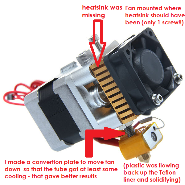
The cooling “system”… A TOTAL MESS! But I was sitting without an internet connection so I had to make do with what I had - being a drawing for a cooler duct which I had downloaded just to see.

So I printed one - which melted on the bed - next print I used a hairdryer on a shoe-box next to the printer to give some cooling and although still a disaster, it was more or less usable - so I printed another one.

Mounted the fans to the ducts and hung them on the best I could just so that there was positive cooling going on.

This involved a lot of Dremel, odd bits of plastic, even a piece cut out of a soft drink can - but now the heater tube and the work-piece were getting cooling even though it looks like something the cat dragged in - it works!

MAYBE a bit too well!!!

The extruder simply would not get to 180 even when set to 205 - so for startup I put a piece of paper over the fans to “choke” them and give the element a fighting chance.

“Why not simply switch them off in the software?” I hear you ask…

Well, for some reason or other the fan control no longer operates so I had to wire them directly into the power supply.

OK. Now she was able to get the heater block up to 180 degrees and extrude plastic - well sort of anyway…

But while I had been sitting around with no Internet and fiddling around upside down on the extruder assembly (difficult!) I came up with an idea:

Seeing as I was going to have to re-make the whole extruder mount . bearing plate why no make it a “quick release” design?

So I designed a plate for the bearing to mount to (and made the shaft spacing a full metric size, not the weird “not metric / not imperial” dimension it is currently with a V-lip at the bottom and a placement stop on the left so that an “extruder mount plate” could fit in and be secured accurately.

All necessary wires would have to get plugs but I have some of them - even heavy duty ones for the heater.[attachment

Then I drew up the extruder mount plate as well.

Now to print them to see if everything worked together and fitted.

So the first “job” with the new cooling setup was these 2 parts - DISASTER!!!

[attachment file=58454]

The basic idea I feel is good but the quality of the print is terrible!!!

So I started changing the settings - and after 2 attempts decided to get a test model that was a lot lighter on filament and time.

Chose a hollow, open on 1 side, letter “W”. Only a few grams and it has enough surface area to write the settings and notes on - trying to keep track of things.

And by the way, I was now using a piece of glass as the print surface because the heated bed was bowing up to a millimeter depending on the temperature - at least she now has a stable, flat print area.

I sort of eventually figured out that there is now too much cooling going on.

This is the kind of artifact issues I am getting:

[attachment file=58455]

In my opinion definitely related to temperature in some way - either filament too low or part too cool.

While waiting for these prints I did an updated extruder mount plate that incorporated a fan with duct to cook the extruder tube.

So just before I hit Alison with a hammer I decided to print my updated design - just to see…

[attachment file=58456]

This is the 2nd attempt - the first one was even worse!

I has downloaded a NEMA17 model from somewhere and I printed that so that I could see if the clearances were all OK and it is a good thing I did because it would not fit so I modified the design again and printed the one in the picture.

It came out pretty bad, better than the first one though and the motor now had enough clearance and there is enough place to mount almost any configuration of part cooling fan ducts.

That was at about 2am last night - totally disgusted I decided not to work on Alison today and guess what - woke up today and I had Internet again…

CHANGE OF DIRECTION:

So I went onto Youtube and got a message from a buddy about the Lowrider and so I went and had a good look at them - both here on V1 and on Youtube - pretty impressive!

Yes it can be built to handle a 1.2 x 2.4 meter sheet BUT I don’t need that sort of size.

1 meter x 800mm with a 150mm Z travel will be more than enough for me at this point so I am seriously considering the change.

And here is the other thing:

I will be needing to put on a rotary axis at some point so cutting a hole in the bed and mounting it there parallel to the X axis is an option that will allow me to machine pieces up to 300mm in diameter and maybe 800mm long - more than enough!

I’ll have to give it some serious though but like the fact that the longest axis is not a piece of tube but a solid table top - much less flex and harmonic vibrations for a start…

Oh - and by the way, how the hell do I turn off filament retraction on the Slic3r that is part of Repetier Host?

I have looked everywhere - know I turned it on at some point - now I cant find it and especially on the “W” the artifacting seems to be originating at the point where extrusion starts again after a long move and the associated filament retraction operation - seems like the first bit of extrusion fails/is dicey and that starts the process which then gets amplified and worse every layer.

Thanks for reading this people - what do you all think?

All the best,
Aubrey.


Have you ran the PID tuning?

That might help you get a hotter hot end.

I love my low rider. Is 150mm in Z really what you want? That seems like a lot. The low rider had the advantage that it’s strongest at it’s lowest point, so having the extra pipe doesn’t hurt, but if you’re milling at 150mm in Z, you might be stretching the machine too far.

As for the 4th axis, the diameter of tree you’re carving (300mm?) depends only on what height you mount it. You won’t be able to mill very far into the surface. The bit can only reach so far. Maybe you’re better off with some kind of adjustable height for mounting. Sort of like a drop table, but for a rotary axis. Also, how do you plan on rotating something that large?

1 Like

MadMan. Lionel,

I’m in Pta. One of the things I struggled with when building my MPCNC was sourcing the bearings, screws, tubing etc. It’s all available, but since we don’t have McMaster-Carr in SA, and the non-functioning post office, get items from China/Amazon is a bit hit and miss. As an example I ended up using normal mild steel tubing for my frame. Dirt cheap (R65 for 6m at Steel & Pipes for Africa), and works, but not ideal. Stainless steel would be better, and I struggled with getting alu tubing in the right diameter locally. I’m sure either is available, I just struggled to find them.

Perhaps we can start a spreadsheet or wiki page somewhere with where to find the various components in SA, to make things easier for others wanting to build MPCNC’s in future.