With apologies to Jefferson Airplane: PlasticFantasticRover
1 Like
I have a question for those with electronics knowledge. My batteries are two paralleled 12V and I’ve got a motor controller Arduino shield that uses TLE5206 to supply power to the motors. 12V is supplied to the motor controller directly off the battery and it looks to me, based upon schematics of the controller, that the negative of the motor power supply is not tied to the ground of the Arduino. I also have a 12V battery charger connected directly to the battery terminals that I plug into the wall when needed. To “isolate” the electronics from voltage fluctuations from the motors and battery charging, I use a number of DC-DC converters to power the electronics, like these:
https://www.amazon.com/gp/product/B07N3TNBH6/ref=ppx_yo_dt_b_search_asin_title?ie=UTF8&psc=1
The question I have is about grounding. I’ve read somewhere (and its been way too long since I’ve studied any of this in school), that the outputs of these converters cannot share a common ground with the input. If true, I cannot ground everything back to the battery negative. I have one 8-36V / +12V converter for a x86 computer, a separate 8-36V / +5V converter for the laser mapper, another 8-36V / +5V for a jetson nano, and one final 8-36V / +12V converter for a linksys DD-WRT router configured as a WIFI client. All devices are connected via Ethernet with the linksys.
In my original build, none of my grounds/outputs of DC-DC converters are tied together and things “seem” to be fine, but I don’t really know for sure… I don’t know where I would get a ground loop if everything was just connected together via Ethernet. Should any of this get bonded together? My robot is built from wood and plastic.
I assume I could just test continuity between the two negatives on the DC/DC converter and if its present, then its all common ground already.
On an AC to DC converter, you definitely don’t want to connect them. I am sure there are ways to make a dc to dc where that would be a problem, but I can’t think of one.
I’m starting to think I read bum information on these dc-dc converters and common grounds. People use them in golf carts and whatnot and to think they aren’t common grounded somehow is suspect.
You guys seen these?
I saw that as well as a few other recent “pico” size sbcs, such as the ROScube. They do have a lot of promise, but the price (though not bad for what they are) is pretty high compared to something like an RPI. I think the DFI one is something like $300+. You could do a lot with those though.
One of my biggest concerns is power consumption and ever since hooking up that celeron board, it seems my battery life has gone down significantly. Though the celeron board I have is spec’ed as having pretty low power consumption for an x86, it’s a desktop mini-itx motherboard powered by a DC/DC converter and a DC to ATX power supply. I don’t have a good measurement of current draw on it, but I think there’s a lot of waste.
I’ve been waiting for the Rock Pi X to come out, but I got tired of waiting and just recently ordered an atomic pi for about $40… It’s based on the same intel Atom processor series as the Rock Pi X will use and I’m hoping draws less power than the celeron (will run off a single 12V/5V converter). Hopefully it has enough umpf to do what I need and the 2 GB RAM limit is sufficient.
I haven’t. I have been pretty removed from the hardware for a while. We use big, relatively expensive computers on our robots. We have plenty of power and we don’t want $1000 worth of computers to be slowing down development of a dozen software engineers.
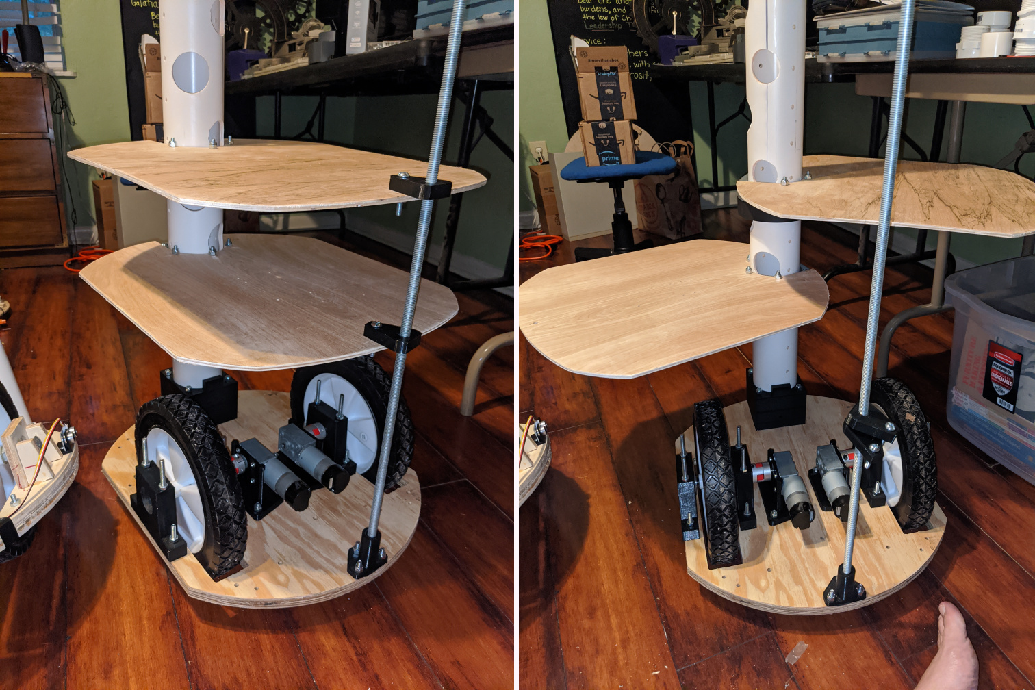
Just a quick update… kids want to go swimming. Parts are printed and assembly mocked up. Picture on left is how it will be in normal operation. Picture on right is with a few bolts removed that allow me to swing the plates outward and have convenient access to them. Handsome foot is a bonus.
3 Likes
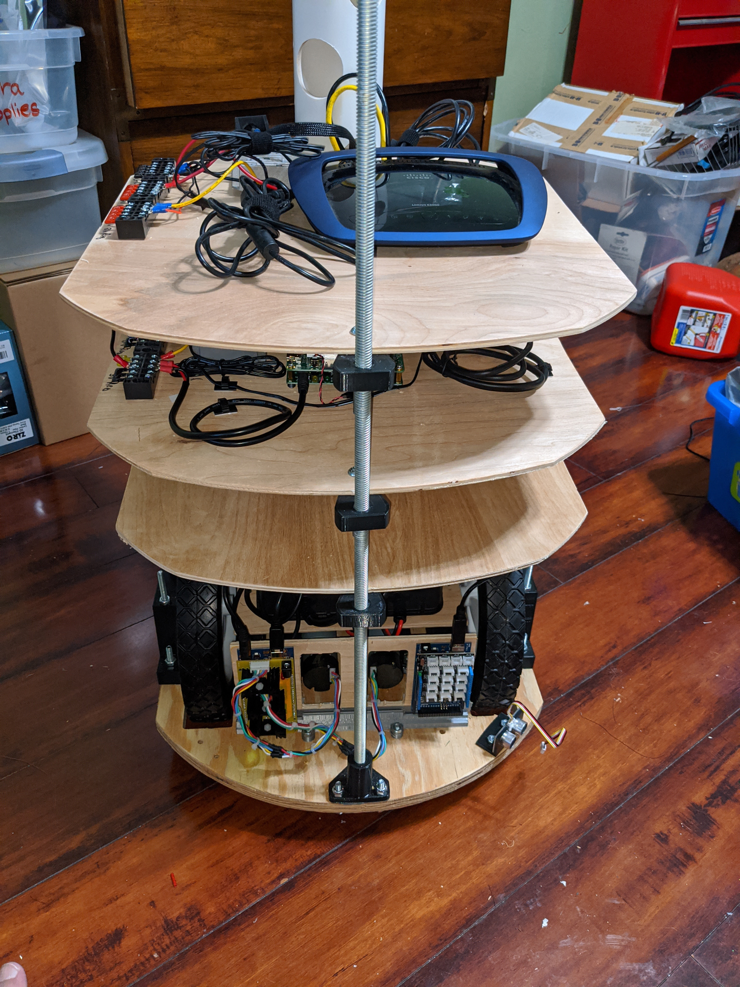
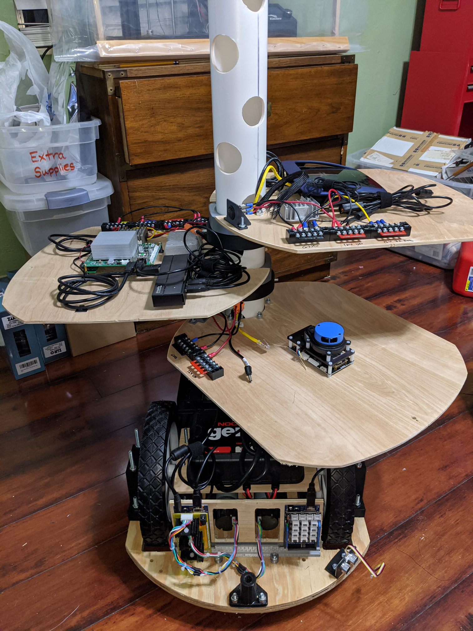
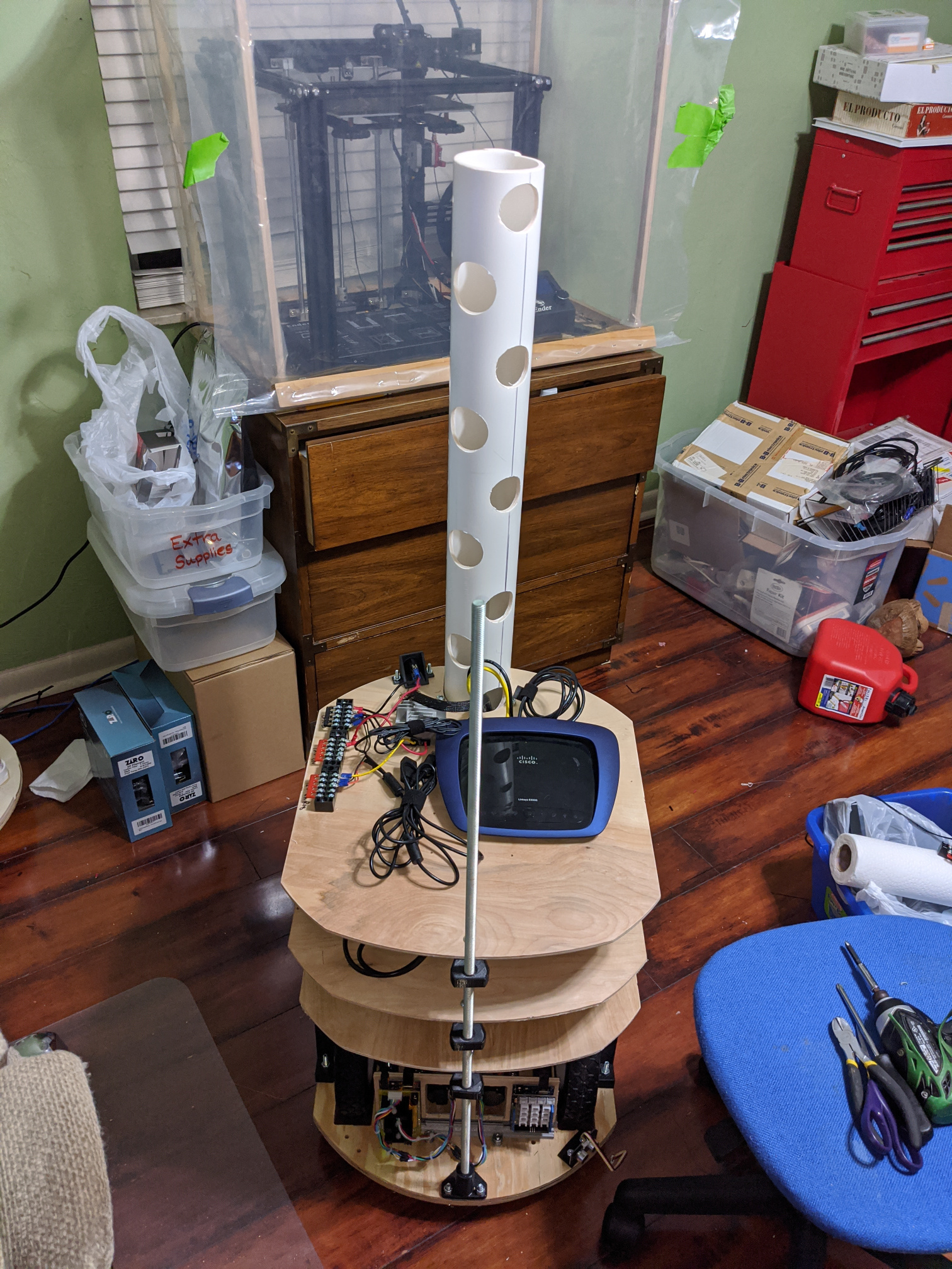
Most everything is assembled except for the sonar sensors and its cabling harness (need to get some more machine screws). I really like the access I have to the various plates. I was getting some weird voltage readings and had to disconnect everything on the battery/fusebox/motor plate. Having the ability to swing the other plates out of the way without disassembling made it … well… enjoyable to work on (If I could only build in a scissor jack to lift it up…) Turns out that my SLA batteries apparently drained so much sitting around that the smart on-board charger wouldn’t charge them and I had to connect a dumb trickle charger to get them up in voltage. Below are some fresh photos. I need to cut the front support rod now that I know how tall the plates will be.
3 Likes
That looks awesome.
It moves much better than the previous build. I think using 3D printed parts resulted in better alignment. It’s pretty quick and nimble without any ‘odd’ sounds like the old one.
My next challenge (before re-tackling navigation) is to figure out the power system. I have an on-board 2-port 12V/8A charger (4A to each battery) that I plug into the wall to recharge the SLAs. I want to keep the electronics on while the batteries are charging, but I’m worried that it (1) might interfere with the charger in determining how to charge the battery, and (2) take longer for the charger to charge the batteries because its also powering the electronics. But since I’ve plugged it into the wall, there’s plenty of power available from the outlet to power the electronics if I implement some sort of switch so that when the battery charger is plugged in, it switches the electronics from battery over to a 12VDC power supply.
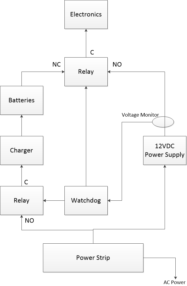
There’s a few ways I might be able handle this, but if I use some kind of relay that is activated by the 120VAC, then it needs to switch fast enough (prior to the charger starting up its diagnostic phase) but also slow enough to give it time for the 12VDC power supply to ramp up. So, I’m a bit inclined to try to make something like a watchdog (maybe ifttt) with a series of relays and a voltage monitor. If the watchdog detects steady 12Vs from the output of the 12VDC power supply (should only happen when the power supply is plugged in), it activates a relay to switch sending power to the electronics from the 12VDC supply instead of the battieres. Then, after a short period of time, it then activates a relay that sends AC power to the charger. The part I’m worried about is the switch between batteries and power supply and whether or not the time between the switch will cause the electronics to drop out.
I would have just ran the electronics while charging. The electronics input should have some power input filtering, or else they shouldn’t be attached to batteries directly.
But this configuration looks fine to me. The capacity of the input filtering is going to determine if it can handle the brown out while the relay is switching. Are you going to have a common ground or switch both Vcc and ground?
I had been running the electronics off the charger but I’m worried that it is interfering with the charging. Now, I just turn them off. Previously, sometimes the batteries didn’t fully charge (the light on the charger never changed from red to green). The charger is “smart” and goes through seven stages. My concern is that the extra load of the electronics might be confusing the charger. All electronics run off DC/DC converters and those themselves may handle any momentary brownout issues.
As for switching, I was thinking of maintaining a common ground. Just seems safer to me, but am I missing something?
I’m trying to think it through, and I can’t come up with a problem for common grounds.
Aren’t there charge controllers that have outputs for the load, inputs from AC and leads to the battery (in or out)?
Not sure… are you referring to something like a solar charge controller or something else?
I don’t actually own one. So I may be confusing other topics. I was thinking specifically of the charge controllers the youtuber Great Scott uses with his lipo batteries.
I’ve ordered some current sensors and will monitor and log the current being fed to the batteries from the charger with the electronics on and with it off and see if I can detect any issues. The charger doesn’t indicate which stage of charging its in (red LED means charging, green LED means done)… maybe, hopefully, it’s not an issue that needs to be solved.
I would expect it to take longer to charge, up to the point of never finishing. If it was trying to charge at 1A, and the electronics were taking 0.9A, then there would only be 0.1A heading to the battery, and it has losses too. But with 7 stages of charging, and me knowing very little about batteries, it could very well be getting confused.
8 stages, it turns out… but based upon my clamp-on meter, electronics currently are drawing about 1.5 A at 12V. That’s “split” across the two paralleled batteries… so maybe 0.75A per battery. The charger does up to 4A per battery and therefore should have plenty of capacity to get it done, but I’m no genius regarding batteries and chargers either and maybe some other issue prevented it from charging fully. I discovered recently that if the battery is too drained, then this charger won’t ever seem to finish (maybe doesn’t really start) and it have to throw on a dumb charger to get the voltage up. I wish the charger had more a few more indicators… but it was relatively inexpensive for an on-board charger.
These are the charger steps:
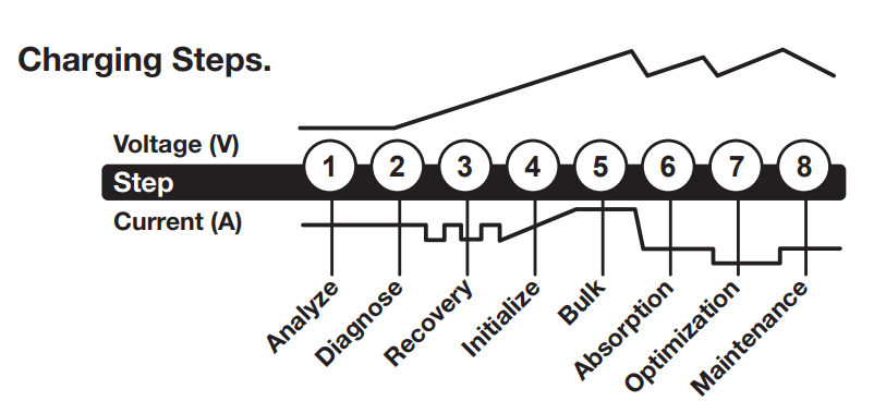
Step 1 & 2: Analyze & Diagnose
Checks the battery’s initial condition, including voltage, stateof-charge and health, to determine if the battery is stable before
charging.
Step 3: Recovery
Initializes the Recovery desulfation process (if needed) for deeply
discharged or sulfated batteries by pulsing small amounts of
current.
…