In the searching I did, anything transparent, that will bend (cold) to that radius is out of stock, due to use in PPE face shields I expect.
I think anything that will bend to that radius could be rolled for shipping, so that shouldn’t be a significant factor. .020-.040 PETG seems to be common and suitable, but also sold out everywhere…
I’ve tried the heat gun approach to bending thermoplastics, but it’s very difficult to get a consistent result. If you can break the pieces down to where they’ll fit in the oven, I think you’d do better. Even then I think you’d need to plan on trimming off the ends.
Making a mold and doing it in three vertical parts might be the only way to go if I can’t find a single clear sheet. The desk mats I linked to above is PVC and I’m worried that its too flexible. I might have a chance tomorrow to go by the store and look at it.
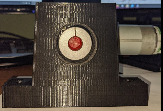
Here’s my first successful solo-designed 3D-printed apparatus. I bought a bunch of sonar rangefinders to place around the base (seven of them) and needed something to mount them to. Thingiverse had two different mounts for this particular rangefinder (seeedstudio) but I didn’t really care for them so I made my own. Its a decent fit but I’ll probably put a dab of silcon around the transducers to make sure they don’t come loose. I’ll mount these to a wooden ring that I’ll cut on the lowrider. The plan is to have the ring below the mounts (secured to the robot base through a series of 1/4-inch bolt-standoffs) so that if there is an obstacle the robot misses detecting, it’ll hit the ring and not the ultrasonic sensor. Now I’ve got to print 6 more of these… tomorrow
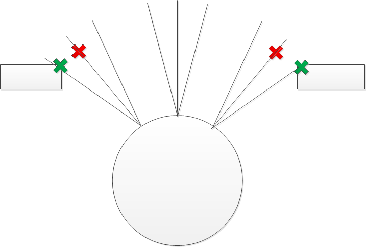
I managed to mount three ultrasonic sensors to the front of the robot (one facing straight ahead and two about +/- 45 degrees looking out radially). It seems to work ‘ok’ for detecting obstacles in the pathway (assuming it gets a good reflection), but I don’t know if it will be effective, particularly navigating through constrained spaces, like a doorway. The problem I think I’m running into is that my robot is rather large and there’s not a huge margin on either side of the robot as it passes through the doorway. The sensors detect the door jamb, but because the beamwidth is 15 degrees it doesn’t know the exact location of the jamb. I think the obstacle is localized on the cost map at the center of the beam and then it gets inflated from there. But if the obstacle is actually on the outer skirt of the beam, but is localized closer in (closer to the robot’s path) then it can create an inflated obstacle that in the costmap that blocks all paths to the destination. See my rough sketch below. On top of that, the minimum range of the sensor is really close to the margin of the doorway so that also creates error. The robot has a narrow path through the doorway so there’s not much room for error. This is what I think might be happening… just don’t know for sure.
The inflation happens for 2 reasons. 1, to add margin of error around the robot. If you are 6" wrong while driving at 10mph through trees, you don’t want to hit anything. So you can add inflation to make obstacles wider on purpose to just give you a buffer. 2. Some planners aren’t capable of planning with the whole vehicle footprint, because it just takes too much CPU. So instead. They pretend the robot is a single point and inflate the obstacles by the radius of a robot.
If your inflation includes the size of the robot, and the planner is using the whole footprint, you are doubling up the size of the robot.
If you are in a relatively safe environment, moving slow, and in a tight fit, you can reduce the inflation due to safety. So roving that inflation would be good for you.
Another thing to pay attention to in tight environments is the cell size of the map. If you have 0.2m cell size and 0.2m to spare around your robot, you need the map to be perfectly aligned with the doorway to find a path through. You can reduce the cell size, which will make the maps a lot more bytes, so you may need to also reduce the total size so your computers can still use them.
Ultimately though, those sensors are going to be hard to use raw. I imagine you could filter them using some bayesian filtering to refine the estimate the actual obstacles, but it will be an uphill battle. Sensor fusion (combining the strengths of one sensor with the strengths of another, while reducing the weaknesses) is its own speciality. Certainly, treating the obstacle as a sphere 15 degrees wide is not correct, but the robot doesn’t know any better from just the sensor output.
I’m confident that the inflation model is operating correctly. However, I need to check the resolution of the cost map, but I think it might be 5 cm and could actually be a big part of the problem since the robot has about 20 cm total margin to pass through the doorway. Thanks for mentioning that. I’ll try to increase the resolution and cut down the size of the local costmap and see if that helps.
I’m starting to agree. I don’t think filtering will help, but can always add it to the arduino code if I suspect its producing erroneous measurements. I believe the issue really is localization of where the obstacle is and I would need to do something like a motorized horizontal scan across an obstacle to try to determine its location from the data, something like assume the angle reporting the lowest distance is the true location of the obstacle. However, I don’t think that’s feasible with an ultrasonic sensor and a robot in motion considering the sample rate. And I’m not buying a bunch of lidars to string around the robot… so if changing the costmap resolution doesn’t help, I’m basically relegated to the kinect depth image to laserscan method… which isn’t the end of the world.
I saw something on youtube where people use clear soda 2-liter bottles to create face shields. Push comes to shove I can buy a few and just deal with the discontinuities of the pieces where they join (use those locations as supports for the platform above it)… it would take about 5 of them to go around the robot. If I can find 3-liter bottles, I might get by with only 4.
I was thinking of filtering it at a higher level. You are sort of already sweeping the sensor, right? As you move around. Also, you have other obstacle detection methods. So if you had an obstacle in the map, and you moved closer to it, close enough that it is no longer in the FOV of the lidar, but now you are picking up something in the range of the sonic sensor, it is probably the same obstacle you were already measuring. If the distance stays consistent, then you should keep it in the map.
The really hard thing, is describing that with code, or even better and harder is to describe something like that with pure math. I think for that to work, you would have to start tracking obstacles as objects, and each sensor could update the state of each object if it sensed it. I think there is probably a solution using a kalman and tuning it so the uncertainty can just barely be kept low with the sonic sensor. Maybe there are simpler ways to do it. The lidar would see the door jams and pass the locations off to a tracker. The tracker could use the sonic data to update the range, and the tracker would publish updates to the costmap.
I follow what you are saying, but that’s a bit more complicated than I want to deal with. The main reason for using ROS was to use what’s already been done before, particularly for navigation… simple arduino programs, no problem, I can create them, but not really going beyond that.
I changed the resolution last night, but it didn’t run because I forgot to plug the battery charger in and the batteries died shortly after I had the robot move. But, in the process of making the change, I noticed that I think I have my costmap footprint off by a few inches. The axis of rotation is not the center of the 20-inch robot circular base, it’s forward (in x direction) by 1.375 inches. I think the footprint in the costmap is referenced to base_footprint though I have not found that specifically stated anywhere and my base_footprint is directly under the center of rotation (base_link). But if that’s the case, then the costmap footprint (as a circle with radius) is shifted by 1.375 inches from where it actually is. I think I need to transform the base_footprint back 1.375 inches from base link, so that it is located in the center of the robot. Not sure it will make a difference with navigating through a doorway, but still.
Progress… I kept getting stuck in the doorway even if I completely disabled the sonar and so I realized it had nothing to do with the sonar. I looked closely at the global path being produce and it seemed to almost want to trace the lethal zone of the jamb. I used recommended parameters of a tuning guide and I still got the same path. I tried over and over making changes and kept getting the same path… even setting the cost, neutral, and lethal factors to zero… it was obviously ignoring my parameters so I realized I didn’t have them in a param file correctly. I tend to find things and mish-mash them together so sometimes things aren’t mashed correctly. After I created a dedicated global_planner_param.yaml file and used turtlebot as an example, I was able to change the cost and neutral factors and it produced a path that went through the middle of the doorway rather than trying to clip the doorway. Longer path, but it doesn’t get stuck… next step is to try out more sonar sensors and perhaps optimize the refresh rate. I’m thinking of doing something like scanning sensors that have lower measurements (something closer) more often than ones with large measurements (something further away). I’ve got to figure out how fast I can scan all the sensors once without interference.
Been busy lately, but today I went to work on the robot and do some checks to make sure some of my problems wasn’t a locomotion issue (i.e., my makeshift wheel/motor assemblies). I threw the robot onto a step of blocks to get the drive wheels off the ground and issued some teleop_twist commands to move the wheels. When driving forward, the left wheel seems to hiccup from time to time. Almost like it loses a command, but also like its getting bound. Same thing happens when I do left/right turns, but not as much. But, when I throw it into reverse after a few seconds, both motors stop abruptly. If I keep sending the twist commands it will start back up after a second or two, but then stop abruptly again. I’m not really sure what to make of this. The motor controller I’m using is out of a Maslow so I know it can drive in reverse without issues. The software software that drives the controller is a modified linorobot file and I’m not seeing any issues in the code. I’m not sure what would cause the problem to occur with the motors moving in just one direction if it’s not a mechanical binding issue, but because both motors stop at same time, it seems to be either a power issue (for whatever reason) or a software issue.
What OS is it running on? Can you add a status message from the software in question? Something you can echo to make sure it is cycling at the right rates. Maybe a diagnostic message?
I just saw it happen to only one wheel (other wheel kept going). I think I’m going to rebuild my motor base/mounts and all… and at same time try to figure out a method to make everything more accessible. I was thinking of a single large diameter pipe that runs along the backside that everything attaches and all cables run through to and allow me to swivel the various build plates so I can work on them. Roughly and very crudely like this:
The mounts are rock-solid. I’d be really surprised if there are any issues with them. However, I’m not really experienced with 3D print designs and I wonder if the 50% infill I used was overkill? There’s four of these (two per wheel) and a caster that will be supporting all the robot’s weight. Maybe 40 lbs?
I’m also making a support mount to take a 3-inch pvc pipe… at 50% infill it’s going to take 17 hours to print. I don’t mind taking the time because I certainly don’t want to have to reprint them. This particular mount (located on the bottom plate) will take a lot of stress. Also, does anyone know if its feasible to glue PLA to PVC? I’d like to make sure the connection between the support pipe and the mount is as inflexible as possible.
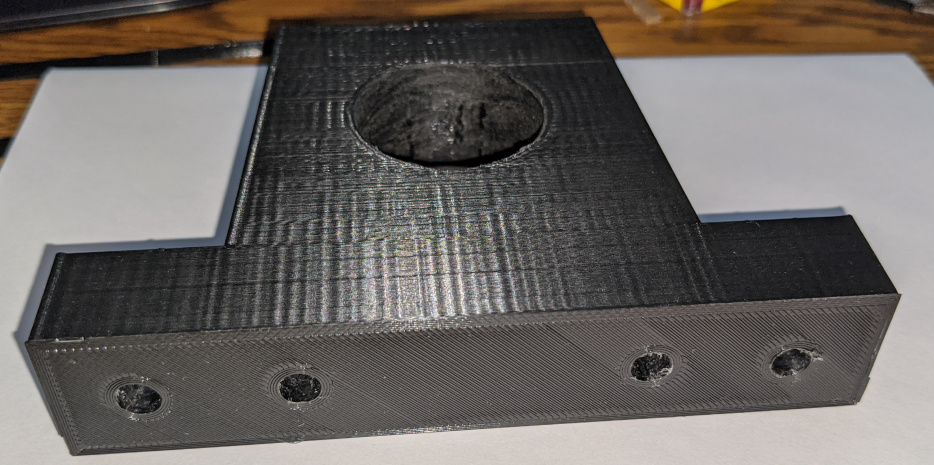
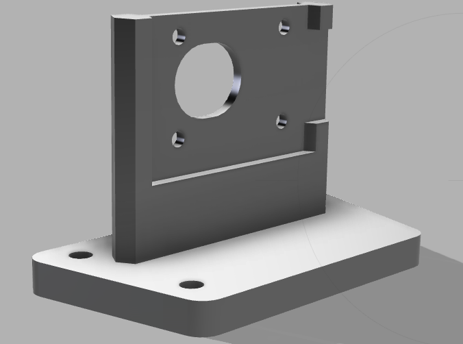
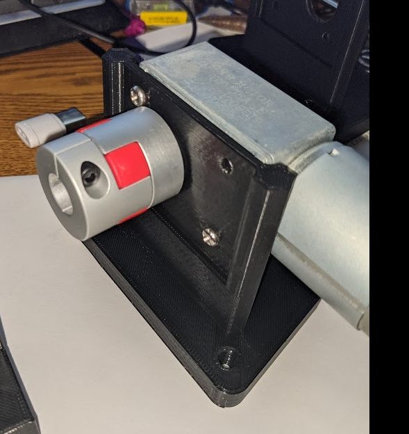
I used 25% on my motor mounts and it seems pretty solid also. This is the design for the mount. The goal was to make sure the motor height is aligned with the axle so there’s no adjustment needed.
I’m almost out of PLA filament and I had ordered some Hatchbox from Amazon week ago and it I’m afraid its been lost in shipping (been out on truck for delivery for two days now…) All I’ve used has been Hatchbox but they are out of stock. Anyone have a recommendation for an alternative?
I’ve been spending too much money on HTPLA from protopasta. I know there are cheaper alternatives, but I get so much value out of a spool, it doesn’t bother me much. The finished product feels good, and they come on cardboard spools, so I can just recycle them.
The High Five Joel stuff looks freakin’ great too. It doesn’t photograph well enough, but it looks awesome.