Yeah, but it took some effort. I just made some led pcbs. They should be here this week.
The parts cost more than the boards. I don’t know how they do it.
Yeah, but it took some effort. I just made some led pcbs. They should be here this week.
The parts cost more than the boards. I don’t know how they do it.
Robots… and cheap manual labor for tasks robots don’t yet do well.
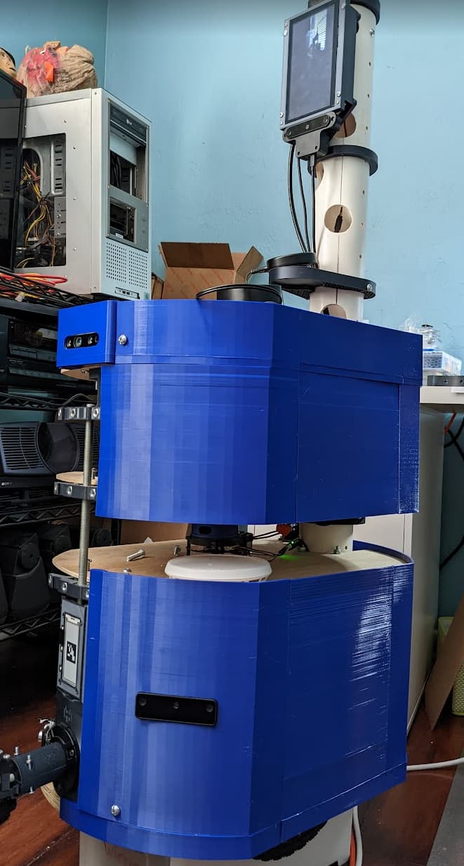
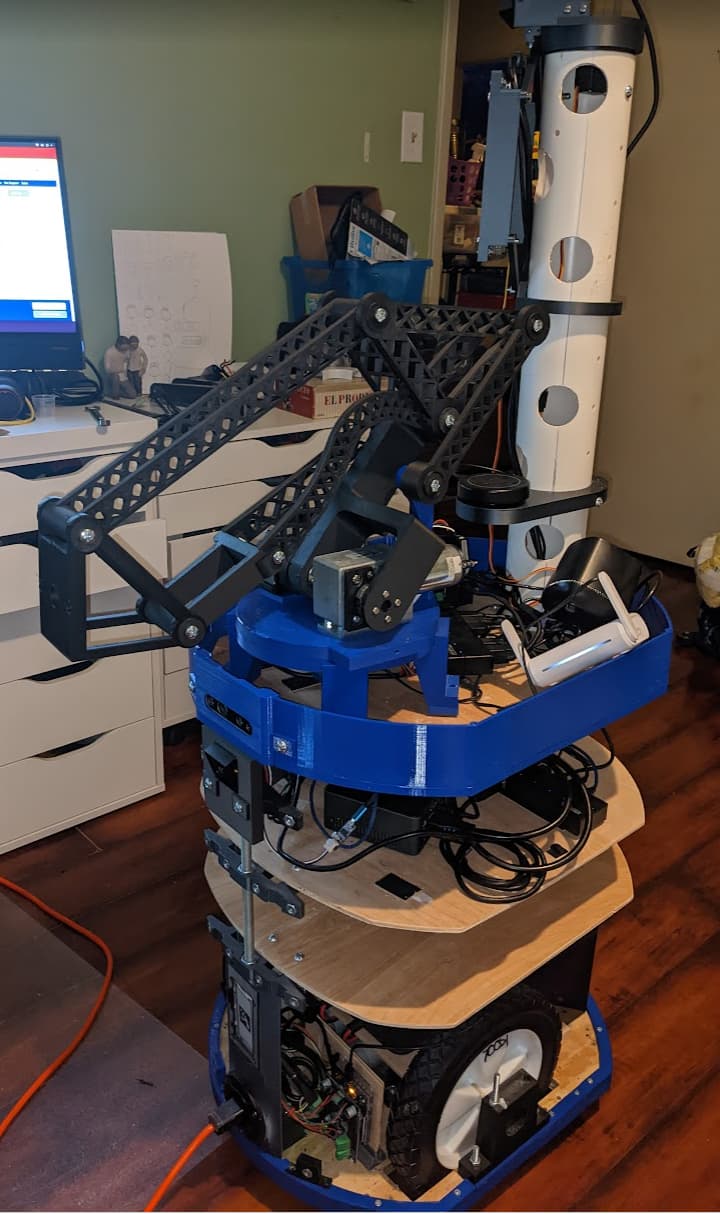
Half way with the skin. Not perfect by any means, but printing each of those pieces vertically is certainly taxing the printer’s capability. Fitment isn’t great, but who cares.
I should have printed the parts in pink so I could call him “Pink Floyd”.
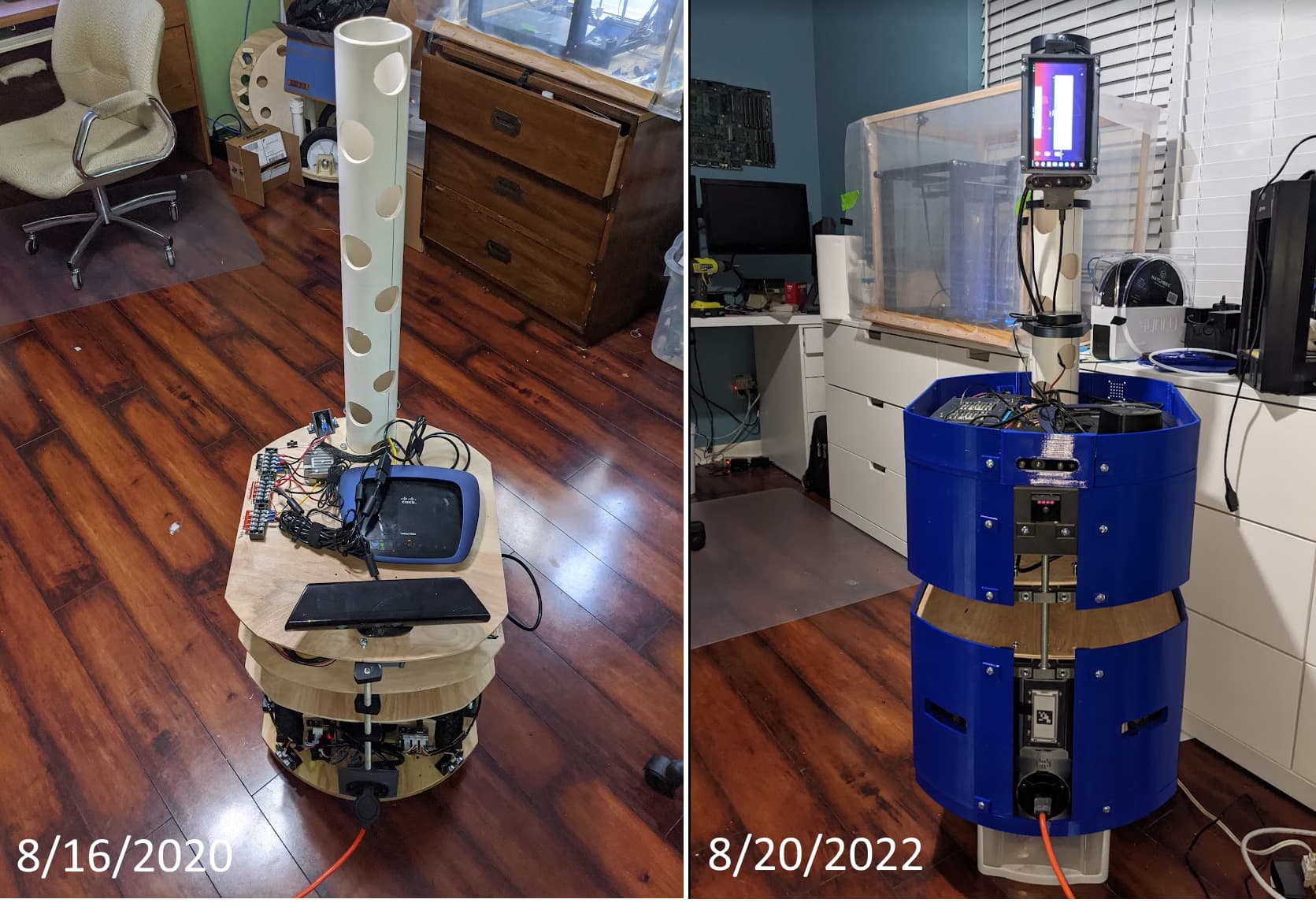
Floyd’s really grown up. I’ve managed to migrate everything to ROS2 now (no ROS1 running at all). Tomorrow I might take it off its stand and actually try to generate a map.
I didn’t think it was possible (and honestly still don’t) but managed to do something that blew my motor control board. I went to reset the robot motor controller and had to unplug and replug power back in. I use a barrel plug connection and somehow in plugging it back in, I managed to do something that caused a spark and now the board is dead. I still haven’t figured out how it happened.
tis but a scratch … it’s just a flesh wound!
I now have a spare motor controller. Turns out my original theory that a blew a fuse was correct. The fuse block I use has an LED to indicate a fuse is blown, but when a fuse is blown and there’s no load applied, it reads battery voltage with a voltmeter and the LED is not illuminated (i.e., looks exactly like it would when the fuse is NOT blown). However, when you apply a load, the voltage drops to around 2V and the LED lights. The first thing I I tend to do when I see sparks is to disconnect the load… I really should start putting sticky notes on things.
Floyd the Robot’s moving again. I need to lower down one of the 3d lidar units to see close in objects.

Can you get enough FOV if you mount it 90 degrees, rotated about X?
That’s not a bad idea, but I looked at the fov and I think I could just point it down more and still get good range. It’s now at ~15 degrees and it has a 65 degree VFOV (120 HFOV). If I did the math right, I could point it downward around 50 degrees and get obstacle coverage from about 2 inches to 6 feet in front of the robot from its current height… which exceeds the size of the cost map (3mx3m). The only concern is that this thing is highly susceptible to floor reflections throwing it off. But worth a shot.
That’s what you get for having clean floors  . Does your sensor have options for thesholding based on intensity? Or choosing the first/last return? Sometimes those things can help remove reflection noise.
It is a little different than I do, because we are always trying to skip looking at grass and vegetation. Presumably, you don’t have that problem indoors.
I’m fairly certain the device has no built-in mitigation methods, but I have the source code to the ros driver and probably could try to add something if needed. We’ll see how it performs as-is and if pointing it so far downwards causes an issue then I can just relocate it much lower… plenty of options. Also, I joined an indiegogo for sipeed’s tof cameras… 100x100 for $19 ( got a four-pack for $76). I was going to try to use them for sides and rear obstacle detection, but can always look to put them up front (if I can keep them from interfering with each other)
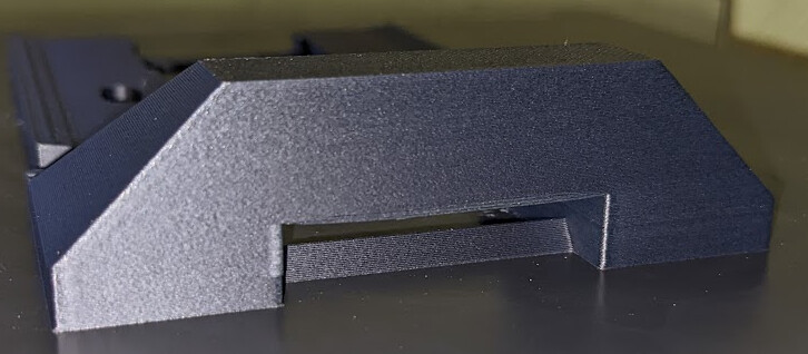
I printed a new mount for orienting the lidar at 50 degrees downward. I used my new Bambu Labs X1C printer that came last night. To say it’s fast is an understatement. According to Cura, it would have taken 4 hours to print on my Ender5 but it took only 1 hour to print on the X1C. Also, I had a pretty significant bridge in the design and though far from perfect, it printed acceptably without any support.
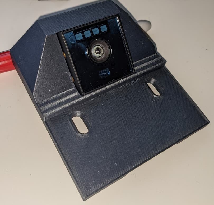
New mount with the lidar installed.
Again. 4x faster than my Ender5.
Unfortunately, when I installed it, I got way too much ground reflection and once I reduced the amount of light projected to mitigate it, it couldn’t see any obstacles on the floor. Cygbot recently posted to github that they are working on a ROS2 node for it and hope they do because the problem isn’t actually a reflection issue I have, it’s that the floor that gets measured is slanted and not horizontal and I mitigate it by lowering sensitivity to avoid detecting the floor… it’s not a TF issue, there’s something wrong in their code and I can’t figure it out (its all about optics and lenses and such).
As Ricky Bobby famously said, “I want to go fast!”
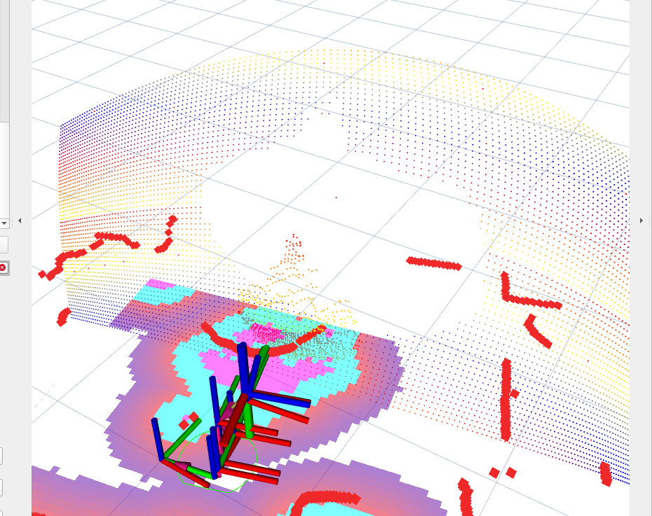
I think I finally sorted out the cygbot lidar unit well enough to serve its purpose. SOOOOO many issues with their code that I don’t think they ever actually tried to use it. They replied on one of my github issues recently that they noticed the same issue a while back… if so, why did they wait so friggin long to say something?? Anyway, the biggest problem is that if there was no object detected at a particular location, they just turned the alpha of that data point to 0 (making it disappear) but left the previous point location (x, y, z) in the pointcloud. This basically left ghost objects all over the place that the costmap function thought were obstacles yet you couldn’t see them in RVIZ unless you set the color transformer to something other than RGB8… So I changed their code to set the distance of the point to be 3m away and calculate the x, y, z from that. That way I have a “wall” of values that the costmap clearing function can raytrace (assuming I understand how clearing works).
All the invalid points comprise, effectivelly, the surface of a segment of a sphere with a radius of 3m. My clearing routine raytraces out to 3.1m so each of those points on the sphere can now clear out the costmap. This was only needed because I had to turn down the sensitivity of the lidar to mitigate reflections and that resulted in a very sparse pointcloud. Maybe if they do fix the other issues with sensitivity and can focus it more downward, but it is ok for the moment.
And just as importantly to that problem getting solved (knock on wood), I’ve managed to get all of floyd’s nodes successfully running on rolling while still on ubuntu 20.04. Every package has successfully been built from source. Therefore, if I go through the painful process of redoing my machine and move to 22.04 then I shouldn’t have any issues… but more importantly, I can use the main branch of Nav2 where they are making additions to it to allow it to report back to higher level behavioral trees. These changes are not “AIB compatible” as they change message definitions and therefore won’t be backported to galactic or humble… hence the need to run rolling.
So maybe I made the arm too big, but something small wouldn’t be really useful. Waiting on the motor control board to arrive from JLCPCB… hopefully I designed it correctly.
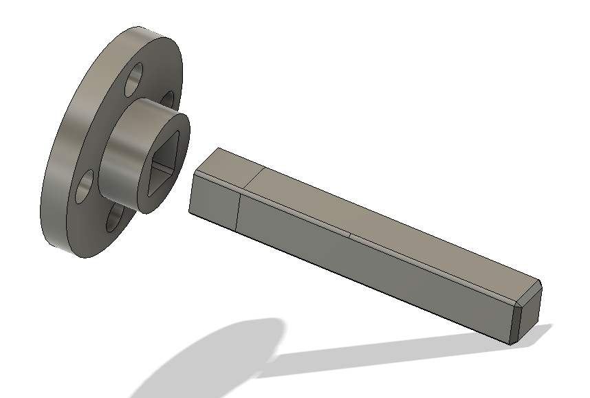
I gave Floyd a gripper. A couple days ago, after snapping several drive shafts printed using PLA and PETG printed vertically (weakest way to print them but it was dimensionally accurate), I switched the design to make it two parts so I could print the ~4.24mm square shaft flat and printed them in PETG since the PA-CF had absorbed too much moisture to print nicely:
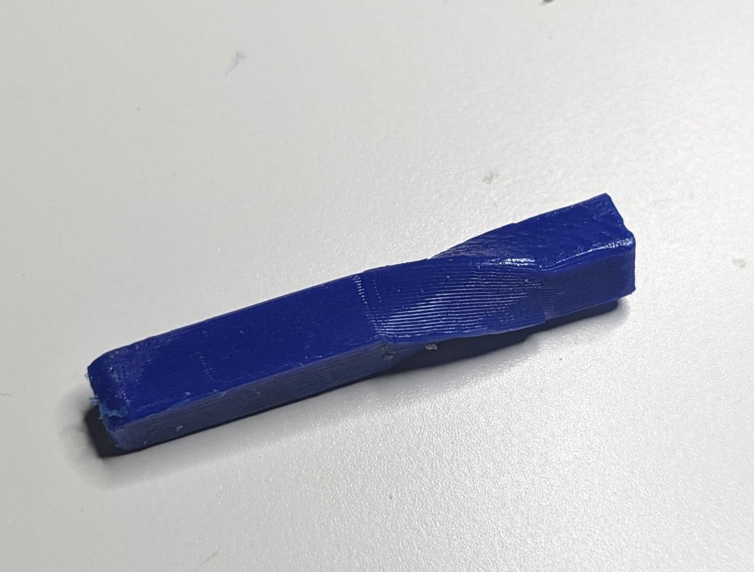
Seemed to work well, but there was a lot of slop and I could move the joints manually without seeing the servo turn. I tore down a finger and discovered that though PETG is tough, it’s just not up for being a drive shaft:
I had been toasting my PA-CF for a couple days in my filament dryer and though its still not very dry (the best it can do is 55C and they specify 80C for drying it out), I was able to at least make the very simple rectangular shafts. Now with them installed, Floyd is rather dexterous:
![]()
![]() wow, that’s a gooder. I’ve seen people do that to car axle shafts building drag cars.
wow, that’s a gooder. I’ve seen people do that to car axle shafts building drag cars.
You may be able to use internal structures to stiffen if against torque in one direction, but probably not both. How much torque are we looking at here?
Supposedly 10kg-cm. Those were printed solid (just upped the number of walls). I don’t think I can make them any stiffer than that with petg.