For your shaft to flange connection problem, could you could turn the flat part of the hole 180 degrees and put a hole through to it for a set screw? PLA takes to tapping pretty well.
I have gone ahead and bought some hubs as it is, but that does sound like a possible solution… I wonder if putting too much pressure at a concentrated point like that would hold up though… there will be 10s of foot-pounds acting on it.
Well, the motor controllers actually work very well. I have positional and velocity control dialed-in, daisy-chained i2c works, and I even implemented soft-homing by monitoring stall conditions. However, as I feared, the motors are not going to be strong enough to lift the arm with the motors attached at the joints. They are relatively strong motors, but only at relatively small moments… damn physics… and though dinosaur arms might be cute, they are not very useful. Stronger motors aren’t cost effective nor likely to help (strong motors are heavier and therefore you need even stronger motors to lift them). Only possible solution I see is to relocate the motors off the joints to lighten the arm and use some kind of transmission (belts, bowden tubes…) to actuate the joints, but that an order of magnitude more complicated than what I was contemplating. So I’m shelving it for the time being and working on the vision part of the robot.
I joined a kickstarter for this project a while back and it finally arrived:
Will see how it goes getting it to do object and facial recognition. Give Floyd some actual eyesight.
I ordered a new motor for the shoulder that’ll take the slow boat from China. 5 rpm with 15 ft-lbs of torque. 3-times more torque geared to the the speed I’m trying to move at. The thing is beefy and doesn’t come with an encoder. Fortunately I have some nice capacitive encoders (from another project) that will fit on the 5 mm motor shaft (motor shaft, not the output shaft).
Been a while, but I haven’t given up on Floyd. Here’s a video of the facial recognition I got working:
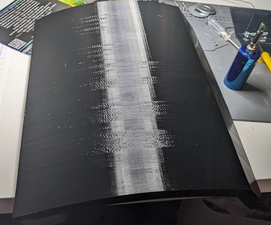
But I’ve got a question that 3D printer experts could help me with. I’m trying to do some PTEG printing and I grabbed an old roll of PTEG (years old, but kept in a bag with a desiccant package at least) and set temperatures to the mid of what was on the label. My goal is to try to print my side panels for Floyd so I wanted something “tougher” than PLA. I started a test print and it came out like crap… the design is a 1/4-inch thick circular arc (was to be about 2 inches tall, but I cut the print short) and I added a brim for stability more than anything else.
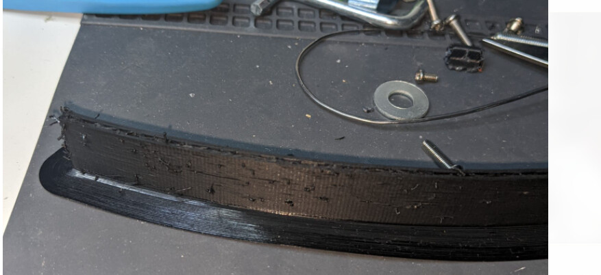
These are my material settings:
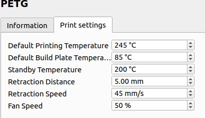
I googled it and saw I should have changed my fan speed from 50% to something lower. I started with Cura’s generic PTEG and just changed print and build plate temps. I’m not sure what other settings I might should try or if anyone has recommendation on a good process of dialing in my printer for PTEG.
5 Likes
Sorry, I never got settings that made me happy with PETG. Glad to see more robot posts though.
I got some feedback from a discord server… going to try to dry the pteg and lower the fan speed even more and see if that helps. The piece I did print, even though it looks like crap and the layers didn’t adhere well, was pretty “tough”. Certainly could withstand being bumped without cracking like PLA would. I might even try to make it thinner, but not sure I can print something very thin 10-inches tall.
Thanks! Will give that a shot.
You might want to knock the fan speeds down a touch, I print stupid fast and use all the cooling I can get.
1 Like
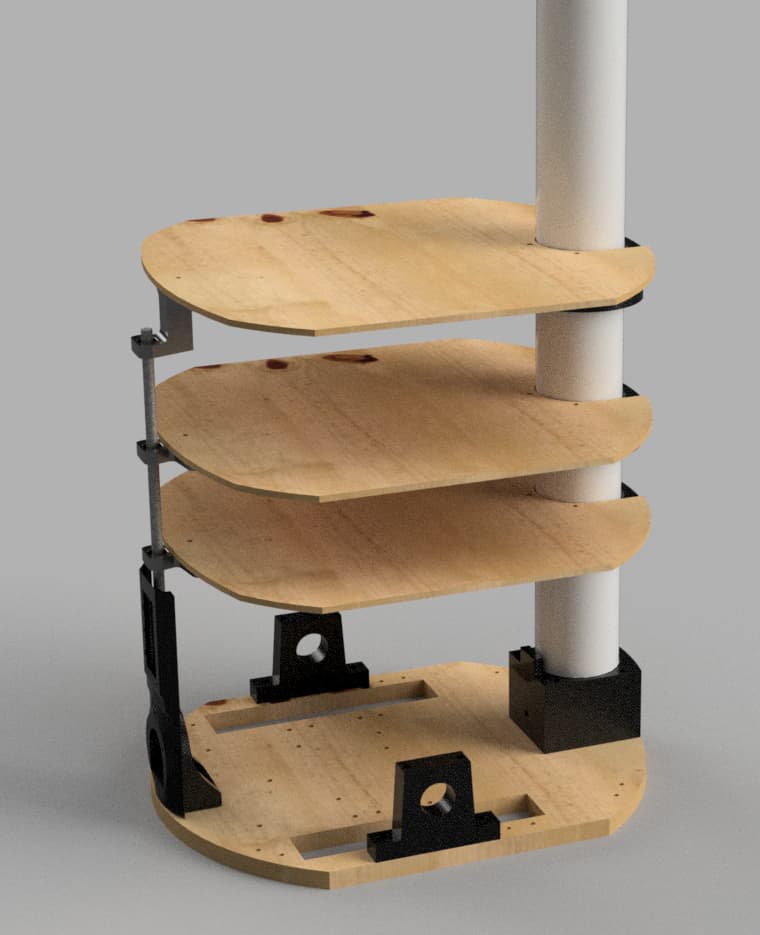
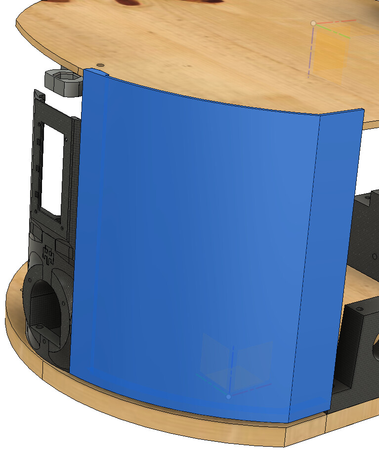
Benefit of using Fusion360 for all the 3D printed parts is that its pretty easy to assemble them to figure out how to make the panels…
1 Like
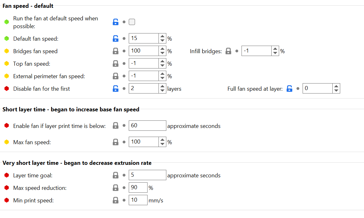
I dried out the filament and turned the fan speed down to 15% (turned it off for first 2 layers)… came out very nicely.

I’m going to test whether I can actually achieve 10-inch high side panel at 1/4-inch thickness… 22 hour print.
2 Likes
… Results of my 22 hour vertical print (it’s laying on its side). The size seems spot-on, and though the surface isn’t perfect, I think I can work with it. Some sanding to get rid of some of the rough spots and I’ve got a robot skin panel.
I think ~10 inches is pretty much as tall as I dare go… I noticed that near the top that the jostling of the print head doing an infill pattern would actually shake the piece slightly… though it still came out correct.
I will say, PETG is some tough plastic. Might become be my go-to filament moving forward.
2 Likes
Or you could wrap it.
Very happy with the result. After a miserable fail (blobs all over the place) I used a calibration file to tweak temperature and retraction settings and I lowered the print speed. 1 panel of 12 done… 36 hours for this one.
Front side:

Back side:
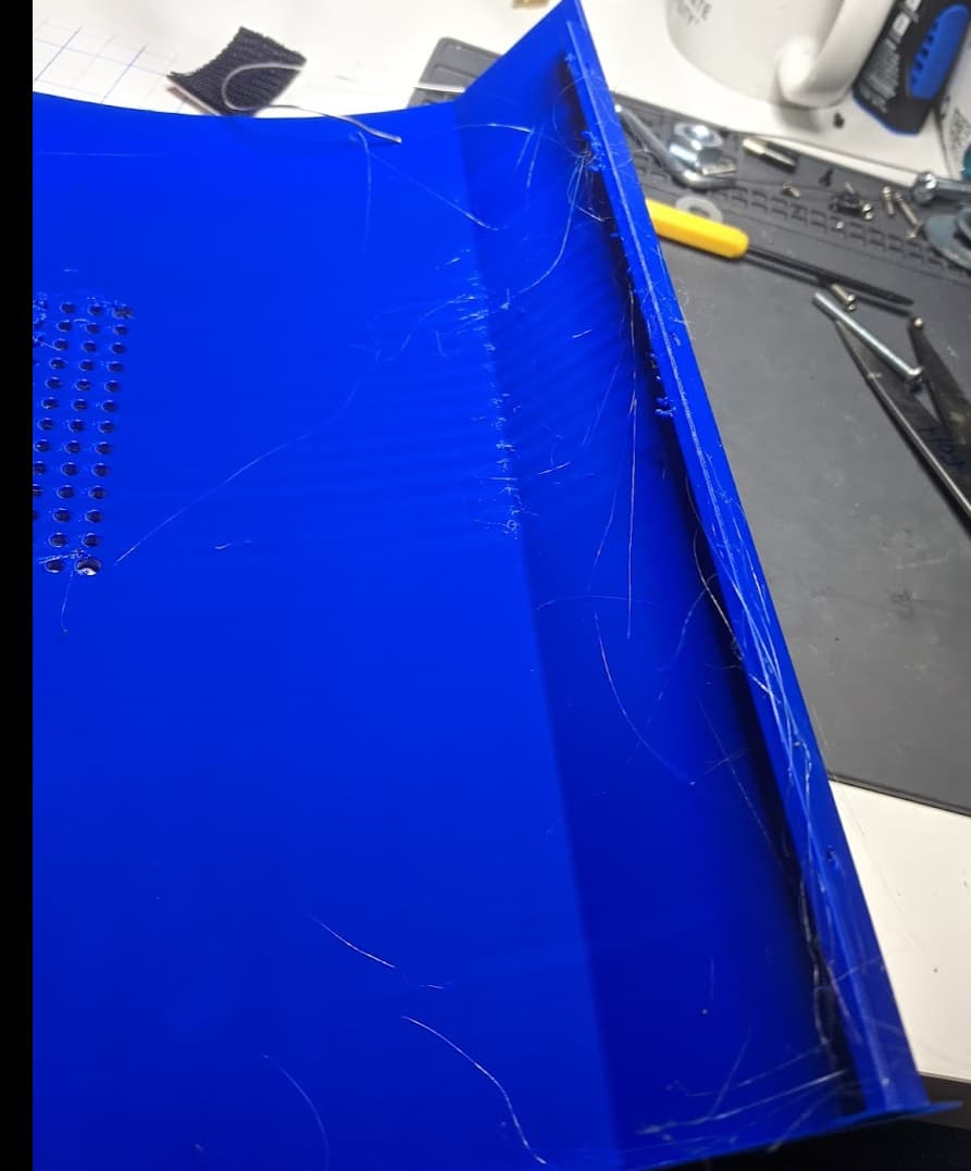
The stringing and blobs on backside is easy to remove and the blobs are in spots that really don’t matter anyhow. Maybe can tweak it even more… I think all issues were where at the layer changes.
2 Likes
It you threaten those threads with a lighter, they will run and hide. Looks really good.
2 Likes
I used my hot air rework station on it.
Yeah, I’m very pleased and thankful I had put my printer on a UPS. We had a storm come through and power cutoff for a few seconds. Would have screwed up the 36-hr print if not on a UPS.
1 Like
More photos of progress.
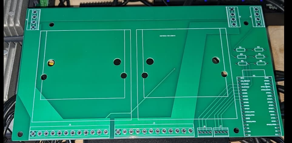
I got really annoyed staring at a spaghetti-mess of power wires with the barrier strips I was using for distribution, so I decided to clean it up and had some PCBs made to tidy it up and used terminal blocks for connections . Power goes into the terminal block at top right and is fed to two terminal blocks for connection to the DC-DC converters. Those terminal blocks then feed a set of terminal blocks at the bottom for connection to the robot’s devices. Soldering it up was fun as I had to use an iron and a hot air gun to melt the solder due to the huge planes and use of 2oz copper. I also incorporated voltage dividers and a spot for an ESP32 to be installed so I can monitor voltage levels (hopefully got the pinout correct). I set it up so I can daisy chain two of them together and just use one ESP32. The one for the top plate has a 12V and a 5V converter and the one for the CPU plate has a 19V and 12V converter.
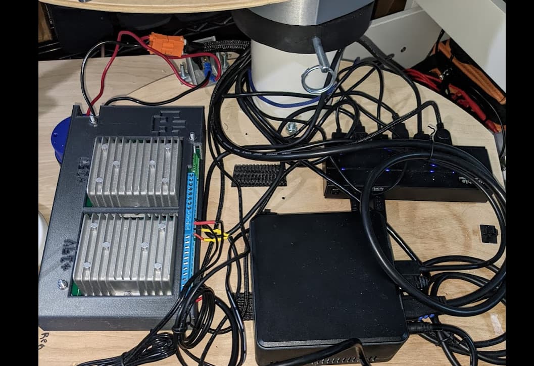
This is the CPU plate setup with the dc/dc converters within its case and connected up. I can’t do much about the rat’s nest of USB cables, but at least the power is cleaned-up
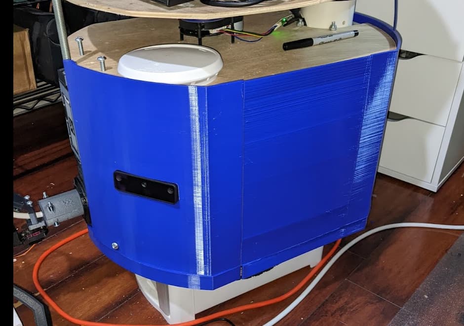
I’ve taken a little break from printing Floyd’s skin (heading out of town) but this is where I’m at right now.
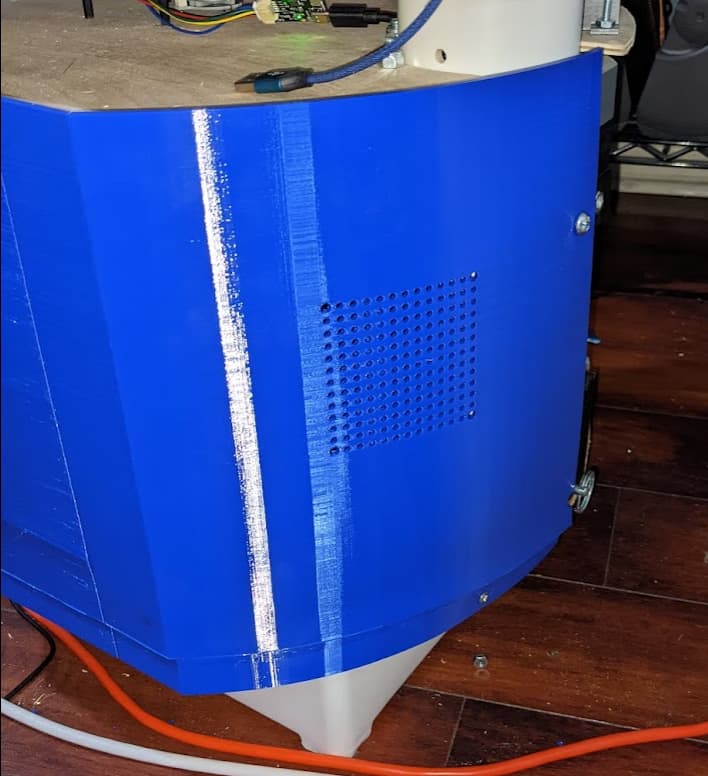
For the rear panel, I added holes to mount a Noctura fan if heat becomes an issue.
3 Likes
That is very serious. A power management PCB is another level.
Yeah… wasn’t all that expensive… $10 a piece when you buy 5. Was cheaper more compact and cleaner than alternatives. I’m contemplating a version 2 where I incorporate current sensors as well, but those chips actually are pricey to just populate the boards with them… and I’m not really sure just how to do it properly/safely, so I just stuck with voltage for the time being.