My main question is whether or not its suitable for charging sealed lead acid batteries. If it would work, I think that’s the simplest method.
I was going to use spring loaded connections to see if I could make the arduino communicate through it. If not, then a swiping setup wouldn’t be all that hard. For power connections, I was actually hoping to use elevator bolts butting together, held in place by the force the magnets provide.
I went ahead and printed out the articulated arm and used rubber bands to make it spring back and it did work… within about 2 cm it would snap together. I used four magnets on each plate (all the magnets I had). Unfortunately, I can’t reliably get the robot to the same space. I can get it to move to move with. 1-2 cm of 0,0 but the problem is that 0,0 isn’t always the same spot. It seems like I’ve run up against the accuracy of the laser scanner to produce odom. I can end up 3-4 cm of the docking arm, but that’s too far away.
I think I need to come up with someway to home in on a target… maybe a camera looking at an AR target
I did consider them, but it turns out that using AR markers was incredibly easy and really precise. I installed aruco-detect package and (after fixing an issue in the software’s launch file) got it talking to the Kinect camera and had it recognizing and locating a 14-cm sized AR code I stuck to an end table in my lab. The aruco-detect module output the location of the AR code with respect to the robot so I modified my docking code to instruct the robot to move toward the marker and stop a bit short of it. Initially I coded it to stop short of it by 0.5m but the target, being relatively low, went out of view of the camera and the robot kept running forward and ran over the docking arm and crushed it. After adjusting the distance to 0.75 m, I was able to test and it consistently stopped within ~1-2 cm of the same spot each of three times. I’m thinking that will be close enough. It’s really good along the y-axis (left and right) and x-axis (forward / back) is where most of the error is… which seems to make sense considering it’s harder to calculate the distance to something in a 2-D image than where it is left/right/up/down.
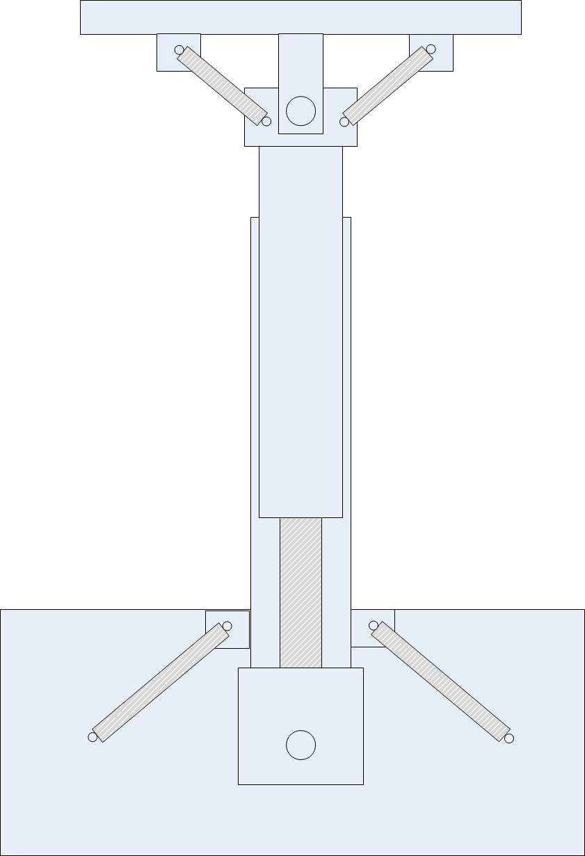
As for the arm, I think I might change the design to a spring loaded piston… something like this (not to scale):
It needs to be able to move both forward and backwards in case the robot overshoots the target a little. The whole piston would be able to rotate left and right and the head be able to rotate left and right as well. With the piston being able to extend/contract, it can get to pretty much any position needed to mate up with the robot… assuming the magnets do their job.
FWIW, many robots use a completely different planner for docking, because instead of being interested in maintaining a velocity and heading, docking is about closing the loop in position and angle. Both of which are pretty different than dealing with speeds. Honestly, stopping in the same place isn’t too hard, but stopping in the right place is.
Yeah, I use the planner to get to the “base” then I turn it to look toward the dock and then use a basic control loop (not considering obstacles, etc.) to move to the docking point. Nice thing is that I can make the place it stops consistently the right place and put the dock there
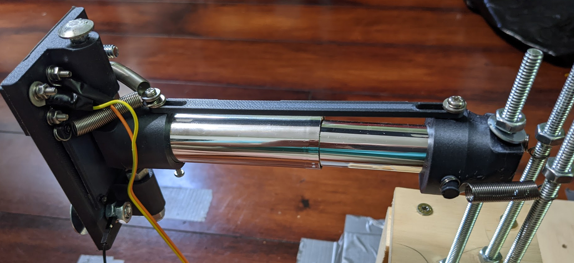
I didn’t have much hope after I assembled everything as it looked way too complicated to work.
Alas, it does work! The red light indicates the relay has been activated, I’m not actually sending any power as I need to make it much safer before doing so.
Some tweaks needed:
More/equal spring tension on the main arm so make sure it returns to straight orientation if it gets moved (it doesn’t do a very good job at the moment).
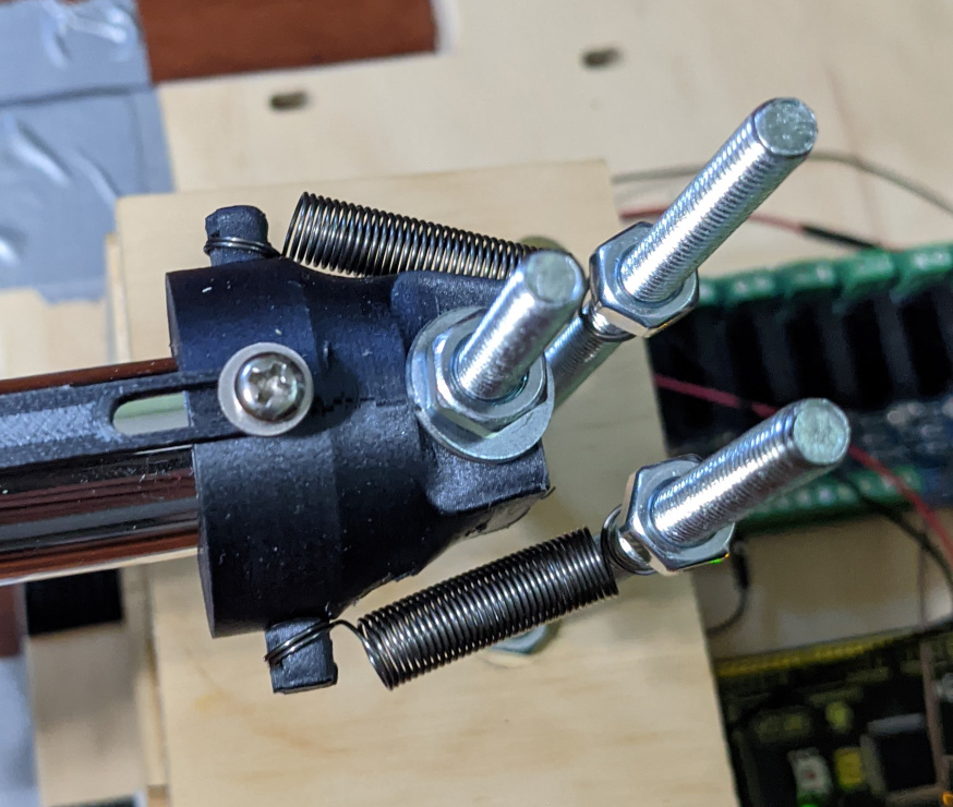
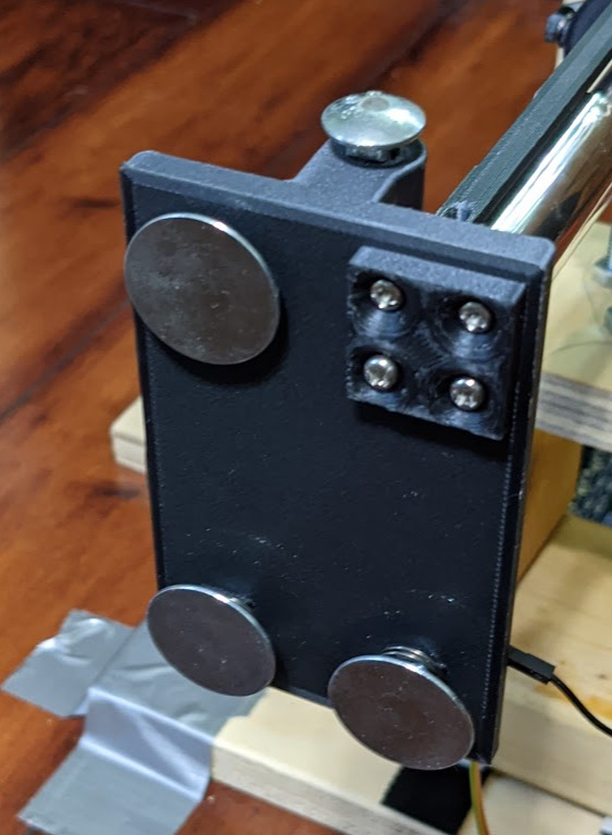
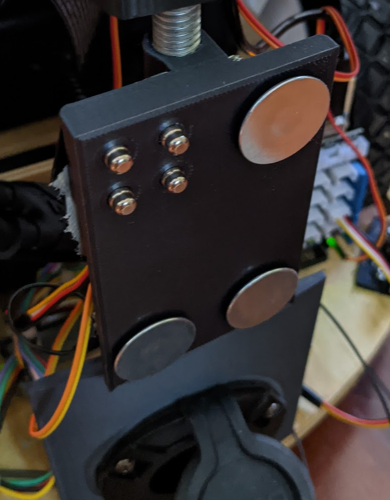
The spring loaded pins I use for detecting when it’s docked and to establish a serial connection needs to be adjusted a little. I had to make a ‘guide’ (for lack of better word) to entrap the pins and make them align with the screws on the other side. If I didn’t have the guide, then pins would try to misalign so the magnets located in the middle (can’t see them) could get closer together. I needed to make the heads of the screws stick out a little further to ensure contact. I also had to install springs under the heads of the elevator bolts because not everything is perfectly plumb… The springs give me margin to accommodate the misalignment.
I use two arduinos (obviously one on robot and one on the docking station). The top two springs/bolts are connected to Serial1 on each arduino. On the robot, the bottom two springs are connected to pin 2 and ground and on the docking station, the bottom two bolts are jumpered together. When the robot and docking arm connect, the robot checks to see if pin 2 is low, meaning continuity exists and therefore everything is aligned with the docking arm. Then it starts to send a “Power On!” command via serial to the docking station. If the docking station arduino reads “Power On!” on Serial 1, it activates the relay. The robot has to send “Power On!” every second for the docking station to keep the relay activated.
One part I’m pretty proud of is what I came up with for the spring loaded arm (the silver thing). It does a good job of compressing to make a solid connection when the robot engages. I try to get the robot to stop so that there’s about 0.5 inches of compression on it. You get +10 points for figuring out what that very common spring loaded mechanism is.
+10 for you. I didn’t think it would be too hard to figure out. Amazing part is that I ordered it from Amazon via prime for $1.33 total… with overnight shipping. I guess they win some and lose some on shipping.
I was playing with ParlAI (from Facebook) to see if it could work as a chit-chat bot on the robot. I tried out the ‘safe’ 95 MB data file version of it (bigger ones take crazy expensive GPUs to run on) and during the conversation it told me its father was its brother. Then it told me its mother was its sister. As sick as it is, I can see how one or the other could be true… but I can’t wrap my head around how both could be true.
I’m working on getting the docking connection to be more reliable and I’ve thought about magnetizing the elevator bolts I’m using to pass the current through. I can get some ring magnets that I can pass the bolt through which should magnetize it, but does anyone know what effect passing a leg of AC power through the center of a neodymium magnet would be? It’s akin to a ferrite bead?
IDK if you still have any pi’s in here, but there is a conference looking for speakers about home robots using raspberry pis:
Not sure if you’d be interested in presenting, but it might bring some more interest to your project, and it would be a good way to catalogue what you’ve done. Maybe even inspire some others.
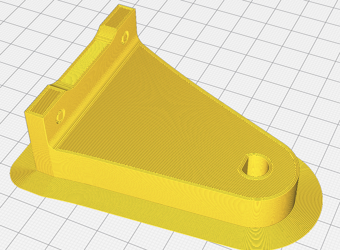
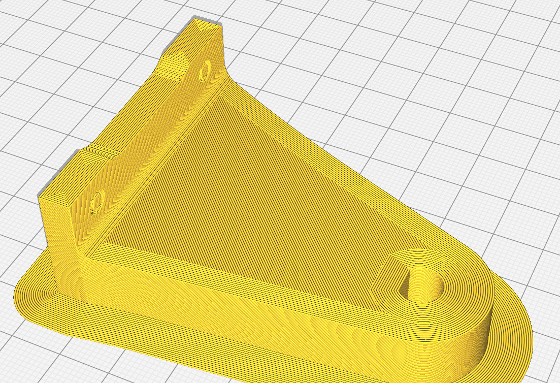
The strong ones have an 8mm D-shaft and so I printed some 3D parts using CF PLA with a D-shaft ‘hole’ so I didn’t have to use flanges, etc. It seemed to work ok until the arm accidentally fell and hit the floor. Now there is a lot of play in connection. Normally, it shouldn’t hit the floor, but it was 6-hours of printing that went to waste. When I printed it, I used 75% gyroid infill and it came out very strong (strong enough I think to support all the weight that’s going to be on it) but I didn’t change any settings regarding wall thickness. This is what I looked like when printed.
I can increase the wall thickness (up to about 11) and make the end around the D-shaft ‘solid’ and then probably lower the gyroid infill because I don’t think I need it that high for the part that’s infilled. My question to those that know is whether I should just give up trying to use PLA and come up with another solution? That is, do you think a solid end will be strong enough?
I have no experience with a 3d printed part on a shaft like this, but I suspect this would eventually work loose regardless of wall thickness.
As an alternative approach, might I suggest mounting a hub on the shaft and interfacing the arm to the hub? The arm could be designed such that the hub was inset, although some thought regarding assembly order might be required. A commercial hub is not required, as a bit of aluminum bar, a drill and tap could provide a DIY hub/lever arm, whatever.
A much more interesting approach would be to print it with 2-3 walls and 10% infill with something like Polycast, and then cast your arm out off aluminum. 8^) Home Foundry! A whole new hobby!..
Lol… I recently saw an article on using wax filament for casting parts, but I think that’s a bit much. I was looking to avoid using hubs, but if that’s the best approach, then so be it.
Its been many years ago. But I use to use Plastic wheels and rubber tires on my weedhopper ultralights. Strong and light. Wheels from 6 to 24 in. Very easy to add drive gears to. A robot I built years ago had good traction on floors and outdoors with the 16" ones
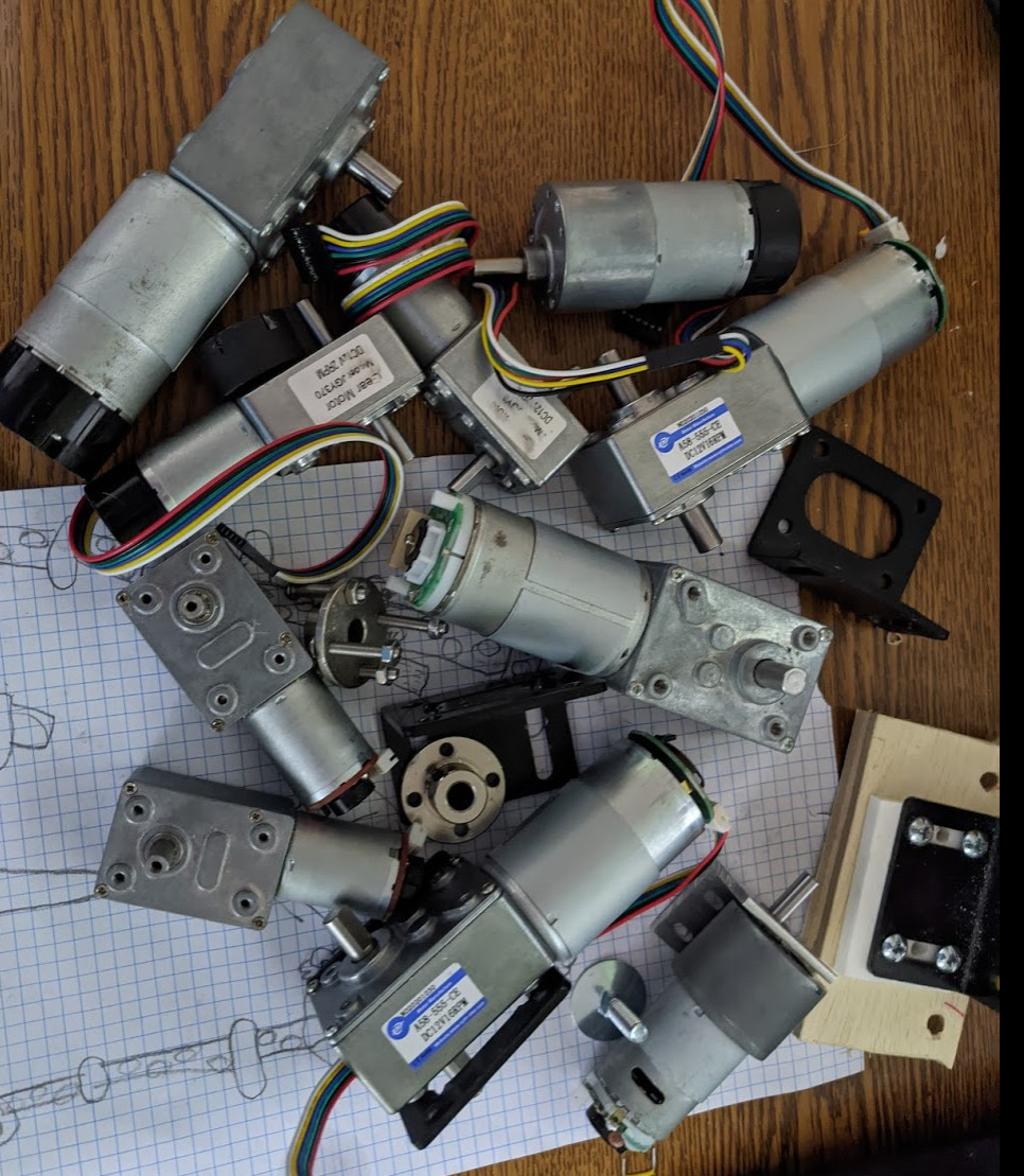
For the robot arm, I arrived at 9 motors total (yeah, nine). I have no idea if the motors are strong enough to lift itself and I only printed parts for assembling the shoulder and elbow. I wanted to find out if it was going to be too heavy before I got too deep into it but since motor controllers that support 9 DC-brushed motors/encoders don’t exist, I decided to take a chance and design a motor controller myself and have it fabbed using JLCPCB (this is not intended to be an advertisement for them). After looking into how JLCPCB charges, I figured out it would be cheaper to build nine single motor controllers than one nine-motor controller. So I embarked on designing a motor controller with the following features:
2+ Amp output motor current
motor current feedback (to detect stall condition)
quadrature encoder support (for positioning)
two limit switch inputs (for homing and making sure the arm doesn’t tear itself apart)
two analog-to-digital inputs (perhaps for force sensors on the grasper?)
serial interface (for troubleshooting)
ISP interface (for programming)
i2c interface (for communicating to ROS node during regular operation)
+12VDC-15VDC power input (to connect to the batteries on the robot)
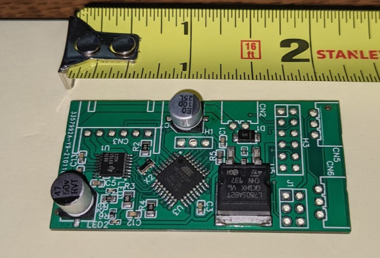
After a lot of digging around what JLCPCB had available in stock for assembly, I ended up combining an Atmega328p with a DRV8876 motor controller and a honking DC-DC converter and produced…
I tried to make it as small as possible as I would like to mount these to, or in the very close proximity, of the motors… and that’s about as tiny as I could get it. I might have been able to use a smaller DC-DC converter, but the batteries voltage will range for 10V (discharged) to 14V (being charged) and JLCPCB doesn’t have a lot of options available for assembly surface at that range of voltage. Regardless, it was just a $0.37 part so beefy it was.
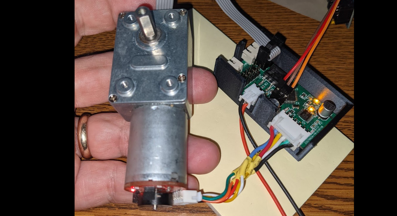
Attached is a picture of it with the connectors assembled (JLCPCB only assembles surface mount components so I had to solder them myself), installed in a 3D-printed case and connected to the motor held by my fat fingers.
To my great surprise, the thing actually works. So far, I’ve only tested out the motor controller and the encoder and it works as it should. I’ve got a lot of programming yet to do … I just hope the i2c works.