Please tell me you named your robot after Floyd in the game Planetfall.
Best robot death scene ever.
Please tell me you named your robot after Floyd in the game Planetfall.
Best robot death scene ever.
You’ve got to be kidding me. I haven’t mentioned that name anywhere, have I? No joke, I just recently settled on THAT very name because of THAT very game. I was a kid when that game came out and it saddened me greatly when he died… damn near to tears. I think I need to play through it again… was my favorite infocomm game of all time.
It’s in the title of your video… funny how a character in a game can stick with us for like 35 years.
There’s a sequel you can play too… Stationfall.
Lol… ok… I thought it was too coincidental, but couldn’t figure out where you might have gotten it from. But Kudos on figuring out the origin of the name. Yes, I played Stationfall as well (big Infocom fan). At the time, I was into neural networks/AI and loved A Mind Forever Voyaging… of course, HHG2G was a big hit with me as well.
TLDR; working better, got new Rock Pi X in mail and installed. Still challenges to overcome using kinect.
I managed to figure out the downsampling. I ended up setting the pointcloud to be published at 5 Hz frequency (processing every 6th frame) and filtering to a leaf size to 0.03. At that size it’s pretty sparse, but good enough for costmaps as it could make out a spent roll of duct tape on the floor and note it as an obstacle. With regards to doorways, the laser scanner catches those just fine… it just misses things above or below its centerline and that’s the reason for the kinect. ![]()
I also added a radius filter to the pointcloud because the kinect is ‘noisy’ and would produce blips out in space that would create small, temporary, obstacles that would stop the robot from moving. I found a 0.1 radius with at least 15 neighbors tended to filter out the phantom particles. This results in rather clean pointcloud_to_laserscan conversion. I haven’t tried actual navigation with the robot yet with the new settings… that’s for this weekend.
I did however discover one rather challenging issue that I need to think on. The mapper’s odom isn’t perfect as its solely based on the mapper’s laserscan+IMU localization capability and sometimes it shifts around the robot’s location a rather small amount… particularly if there is an obstruction nearby. The problem is that if the kinect sees an obstruction right at the edge of its minimum obstacle distance, and the robot’s localization “hops” back an inch or so, and the costmap will get marked with an obstruction, when the robot hops forward to its correct odom, the obstruction cannot be cleared anymore because it’s less than the minimum obstacle range or the pointcloud-laserscanner (I hope that makes sense). I’m thinking I might have to use two difference ranges, one for marking and one for clearing. Something like 0.4/2.5 for marking and 0.3/2.6 for clearing. I think this means two different obstacle layers (one mark only, one clear only).
Also, all of this is now running on the Rock Pi X engineering sample that arrived a few days ago. Having some issue with Ethernet working off a cold-boot (will see what they suggest as I posted an issue to their forum). It makes it a challenge to use it headlessly when you can’t SSH into it, but it’s nice to have everything on one single machine that’s the size of a RPI.
Honestly. You have reached the bleeding edge of robotics. These are the problems we struggle with all the time.
The different limits for obstacles is a good idea. IDK how you are integrating the maps. But you could maybe just pass the sensor data through a filter that removes obstacle measurements under a certain distance, so they can’t be added. But the measurements that would clear them stay in there.
I had tried to use the pointcloud_to_laserscan node in hopes it would use less CPU time, but using it created a whole new set of challenges with marking/clearing of obstacles. I’ve gone back to using the pointcloud directly in the obstacle layer and I don’t see any significant change in processing time (using it as a source in the ‘costmap’ map type, not a ‘voxel’ map).
I think there was no value in trying to convert the pointcloud to laserscan because even with it, the obstacles would get cleared off the costmap when out of view of the kinect. This might be a pointcloud issue with ROS1 that has never been addressed (found a recent post where I think someone is having the same issue). The STVL (spatio-temporal voxel layer) that I tried out before but used way too much CPU apparently can handle this ‘deadzone’ and I might give it another shot since I’ve managed to filter down my pointclouds. Still, not sure if the Rock Pi X can handle it, but it might be worth a try. If it can’t, I managed to a score a good deal off ebay that I might just install… won’t have to worry about CPU capacity for a long time (battery capacity maybe… CPU no).
Coolest thing since sliced-bread. With the filtered=down pointcloud it runs with no issues on the Rock Pi X. I set the obstacles to persist for 7 seconds and it seems to last long enough for Floyd to get around them. It also worked well when I walked in front of the robot and then out of its way… It stopped and after 7 seconds when the marked areas decayed away, it resumed (quick enough before the full recovery behavior kicked in).
So I think ![]() I got obstacle detection working pretty well now… I’m sure I will do some tweaks. I had a couple of instances where the global costmap got messed up by people walking in the hallway and the robot could briefly see them, but then never could see the same spot when they walked away (because it was moving when they saw them and lost view of the spot)… so the costmap got marked but never cleared. I couldn’t then command Floyd to go to the twins room because there was no path through the hallway. I made it a temporal map, and redid the “experiment” and the marked spots decayed and all was good.
I got obstacle detection working pretty well now… I’m sure I will do some tweaks. I had a couple of instances where the global costmap got messed up by people walking in the hallway and the robot could briefly see them, but then never could see the same spot when they walked away (because it was moving when they saw them and lost view of the spot)… so the costmap got marked but never cleared. I couldn’t then command Floyd to go to the twins room because there was no path through the hallway. I made it a temporal map, and redid the “experiment” and the marked spots decayed and all was good.
I think I set a personal record for reinstalling ROS on a new computer. I put in an i7 NUC in place of the Rock Pi X, installed ROS and all needed packages, and copied all the files over in less than an 30 minutes.
Surprisingly the i7 (with a reported 15W TDP) doesn’t use a whole lot more power (maybe 0.5 to 1.5A) while running compared to the RockPiX or AtomicPi… I think the i7 clock speed changes based upon load and that’s how power consumption is minimized… not bad for something seemingly a bazillion times faster.
With the extra headroom, I upped the local planner parameters and increase the number of samples (vx, vth, sim_granularity) and the planner runs much more smoothly and seems to navigate without nearly as many ‘failed to produce paths’.
I’ve been working on fine tuning the robot’s ability to orient itself to a particular direction and nothing I did in local_planner seemed to help… often off by 10 degrees even with tolerance set for 5 degrees. I thought it should keep trying to reach 5 degrees, but it didn’t. So I wrote my own code to issue twist messages and implemented a simple P controller. I set the goal to within 0.015 radians (~1 deg) and to my surprise it never reached it. It would get close and then sit there about 5 degrees off constantly sending twist commands but the robot stayed still.
After digging through the arduino motor control software that I lifted from linorobot github repo, I discovered that the kinematics routines in it used integers for RPM. When the robot gets closer to the desired orientation, the twist move commands get smaller and smaller, and the arduino software converts them to an RPM value for each motor. But because I have large wheels and wide wheel-base, the computed target drops below 1 RPM and because its an integer, it becomes 0 RPM. Therefore the robot stops short of the complete move (about 5 degrees or so). So, I edited the code and changed everything over to floats and it does a nice job… pretty precise.
I now have hope I can build a docking system for it without too much complexity.
Type errors are the worst kind of errors. Well, one of the worst.
I would have probably added and I term (integrator) to the controller first, and that might have worked, but making the controller more precise is always better. If you had added an integrator, it could also have overshot once it got over 1.0 and taken a long time to “unwind” the integrator and return to below 1.0.
I was really trying to troubleshoot move_base to make it perform better to see if I could use if for docking and the code was (initially) intended to help me figure out what the problem was. I was thinking maybe motor backlash at first, but I knew there wasn’t enough of it to account for the amount of error. Then, I thought maybe the odom was really bad or something. But when I saw that using the code that it was still sending twist commands and the motors not responding to them, I knew the problem had to be the motor controller (or motors).
I’m not really sure why they used integers for the RPM that got returned by the function call because they used doubles to perform all the math up until the return function… which is crazy since that level of accuracy isn’t close to being required. In addition, they wrote it to run on a teensy 3.5 that has a float FPU but does doubles via software emulation. I’m going to post something on their repo asking about it. Mine is running on a Mega anyway, so I just changed everything to use floats.
Anyway, if I do continue to use the code (maybe for a docking routine if move_base doesn’t work for it) I’ll update the code to use I and D (unless there’s a reason not to add D?)
In my linux code, I don’t ever use floats. I use a double for anything that doesn’t represent an integer concept. Something like the size of an array is an int. I get away with a lot because I run in i7s most of the time 
D is fine, it reduces short term overshoot. The I term handles steady state error, but they are dangerous and evil. I write PID with a limit in the size I can get, and I try to think of ways it needs to be reset. P is definitely much more robust.
Most of what I do these days is Python, so it doesn’t really matter. Not too long ago, I wrote some software that modelled radio propagation and I multiplied all my floats by 100 and converted them to integers (so -110.41 became -11041) and then used CUDA to perform GPU-accelerated computation. Combined, it speed things up tremendously. It ran the calculations in minutes rather than hours.
I hear that. I almost ripped a Maslow CNC apart by playing around with I.
Absolutely. I haven’t done much optimization recently, but if you do know what your bottle neck is, you can really speed up the whole program by focusing on one area and doing tricks like that. GPU is huge. In the stuff we’ve done, 20x-200x is typical (especially for not very optimized code).
My favorite trick was for this code where were trying to basically fit a polynomial, but the optimization wasn’t just closest fit. So we were doing it brute force. Checking some reasonable values for each term. It ended up being 4 nested loops. I looked at that code a long time and ended up moving the offset term into the middle loop, and because of the way we were treating the offset, I could just compute it. It also had the most values, so I replaced an outer for loop with one calculation, and it went about 50x faster. This even translated into the embedded system it was intended for and it was after a bunch of other optimizations. It was the final key to getting it to run real time in the car and we drove it later that week. It was great.
I’ve started to work on a design for a docking mechanism and since I know it will be hard to achieve a perfect alignment by moving the robot, I came up with a design to allow for the power head and power receptacle to ‘snap’ together using magnets. To work, I am thinking that placing the docking station power head on some kind of spring-loaded articulated arm would be relatively simple and give some flexibility in alignment. I’m confident I can ignore trying to align in the z axis (height) as that’s fixed. The idea is below:
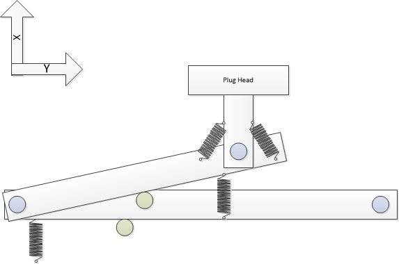
The theory is that if the robot can get close enough such that the magnets start to interact and pull together, the arm can articulate and accommodate a move in the x-axis and y-axis as well as rotation of the head. When the robot pulls away to undock, the tension on the springs (hopefully) will be enough to disengage the head from the receptacle and the arm snaps back to resting position.
Any thoughts or better ideas? Open to suggestions.
Robot vacuums have the pads on the bottom and big push pins to touch them. I suspect it is because the distance to the ground is very constant, and that saves at least one degree of freedom. Magnets are going to need to be very close to snap at all. Like within 1/2".
Are you just feeding the pins with low voltage DC (12V)?
I think you’ll want to have some knowledge to give the planner or higher level control that you’re there, so it can back up and try again if/when it fails.
If it fails a lot, you might want it to slack or text you to ask for some help.
My hope was that I could get real close on x,y and then turn the robot to get close enough to align. I haven’t tried to see how much pull the magnets would exert, but 1/2-inch accuracy seems a bit daunting with move_base. I was thinking of using move_base to get about a foot away, and then using my own routine (like what I did above) to move in close and connect.
My coworker suggested looking into wireless chargers. Maybe I could get the robot to drive over a docking station well enough and then use multiple chargers or something to get the current level I need. Obviously do so would eliminating the onboard charger I have right now.
I’m not entirely sure what voltage to try if I stick with my current plan. It’s clearly safer to use 12V but if I do that, then it would prohibit me from just plugging straight into it from an AC extension cord like I can do today since the onboard charger would have to be relocated to the docking station. Regardless, before I did anything with power I wanted to see if I could just get the thing to reliably connect.
I think you’ll want to have some knowledge to give the planner or higher level control that you’re there, so it can back up and try again if/when it fails.
Either voltage that I end up with, my thought was to have an arduino controlled relay in the docking station that will only activate when a serial connection is made between the robot and docking station and the proper command sequence is sent and maintained. If the sequence fails, then the docking station would disengage the power. I was also going to use two pins on the robot’s arduino to look for continuity that would happen when the power connectors mated. That would stop the robot from moving and initiate the serial connection. If the serial connection failed then it would know it made imperfect contact and back away and try all over again.
Lol… the other night my wife woke me up saying my robot was complaining (I sleep with noise cancelling earbuds in my ears so I don’t hear anything). I apparently didn’t plug the cord in well enough and fortunately I had programmed him to start to complain about dying soon when his battery got low. Worked like a charm.
I also had made an IFTTT skill to report when battery is low, but I couldn’t hear the text alerts. It did come in handy couple weeks ago while I was at work and I was able to get the wife to go in and plug him in for me.
I think the wireless inductive charging is well worth looking into.
If using physical contacts, I HIGHLY recommend sliding contacts of some sort.
Spring loaded arrangements are prone to getting dirty / oxidized / whatever, and this result in a high resistance electrical connection that is likely to overheat and melt and start a fire.
Contacts that slide relative to each other while making connection are self cleaning and much more reliable electrically. Think about the way AC plugs, Powerpole and JST connectors, etc. work.
The robot vacuums are probably a good example to follow, as I’m sure they’ve put a lot of work into reliable, safe connections.
Granted the 12v DC is safer, but a relay that only energizes the contacts after Floyd is the correct position might be a good idea regardless of the AC/DC and supply voltage chosen.