Cheers! 
Been thinking about how to dock the robot so it can charge itself. I know I need new batteries as it is because I get about 5AH out of the pair of 20AH batteries… robot moves like a drunk when its batteries are low… it’s rather comical… reminds me of college. Regardless, if I can get it to dock and charge, maybe the batteries will last longer.
I don’t know if I’m going to get navigation accurate enough to move the robot precisely to a point that it can drive up and dock itself like a robot vacuum does (I’m going to feed it 120VAC so safety is a bit of a concern). Since a plan was to include an arm, or two, in the design, I was thinking of putting the power inlet at the end of the arm and let the arm ‘dock’ with the wall mounted power port. The idea is to have some kind of coupler with interlocks, mechanical and/or signal-based), so the AC power doesn’t ever get applied unless the robot is connected. I think I can navigate the robot close enough so that using the Kinect camera and moveit module, the robot can position the arm to the correct spot to couple it with a power port, activate the interlocks, and start the charging.
I was inspired by this design where the arm assembly moves up and down…
My design would be a bit different and maybe built to handle more weight, but I was thinking of stealing from ryan the idea of using bearings on two different 3/4-inch EMT with two motors and leadscrews to have two independent platforms that can raise up and down (crudely shown below)
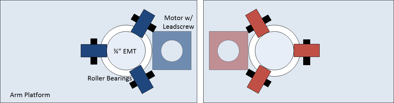
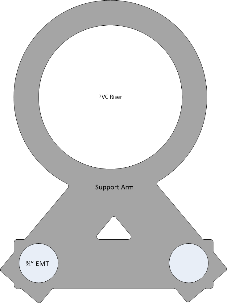
The motor w/ leadscrew would be mounted to the base and a coupler would be attached to the arm platform so it would raise up and down as the leadscrew turns. The two EMT tubes would be fixed together at the bottom and the top for stability and they would also connect to the PVC riser so it doesn’t sway (crudely shown below)
See any issues… thoughts… suggestions?
1 Like
TLDR; Speech recognition working. I now need to find out how to get the robot to prcoess the commands. It needs some kind of brain. I’m not sure what to look for as examples of what other people have done. I don’t want something more than a straight up state-machine… I think?
I now have the speech recognition/synthesis working on the robot. I’m using Mycroft software installed on a Respeaker Core V2. It works pretty well (up in a relatively quiet environment in my lab) but I’m using the built-in wakeword, “Hey Mycroft”, as I haven’t tried to train something different… its not a simple task to do so… I might just name the robot Mycroft and be done with it 
It was an interesting challenge to also get ROS installed on the Respeaker. The Respeaker uses an RK3229 processor and they provide a Debian build for it. I tried to get Ubuntu on it using the prebuilt image of an RPI but no luck. Didn’t even boot and my googling turned up nothing. Since the only prebuilt version of ROS available for an armhf processor is limited to Ubuntu distros, I had to build ROS for source. It had a few hiccups along the way, but this time googling got me through and I have it working.
I think Mycroft will work well because it has “skills” that let’s it respond to questions, like “What’s the weather”. You can create your own robot-centric skills like “What’s your battery level” or “Bring me a beer”, but the Respeaker runs at about 75% CPU usage consistently and I wanted that kind of processing done elsewhere in something a bit more capable than a Mycroft skill. So I ended up writing a simple python script that runs on the Respeaker at startup that listens to Mycroft’s ‘message bus’ and publishes to a few ROS topics what comes across it. Right now I publish when the wakeword is detected, whenever Mycroft hears something it publishes what was heard, and whenever Mycroft says something it publishes what was spoken.
When Mycroft doesn’t know what you are asking (e.g., “Whats your battery level”), it goes to a fallback skill and says something like “I don’t understand”. So I deleted all the fallback responses so Mycroft is just quiet. The idea is that Mycroft and the robot’s “brain” will function mutually exclusive such that Mycroft will respond to whatever Mycroft can, which is mostly social stuff (what’s the weather), but because the robot’s brain will be listening as well, it will respond to whatever it can, which will be mostly robot stuff (e.g., “Bring me a beer”). Ultimately I will turn that code into a Mycroft “fallback” skill and publish to ROS only what Mycroft doesn’t understand and if the robot’s brain doesn’t know what to do, the robot will respond back to Mycroft as such and then Mycroft will provide a “I don’t know what you mean” response… just to tidy it all up. Right now, he’s just sits there silent if he’s confused.
1 Like
I made a lot of progress with the speech system. I can tell it to go to a particular room, turn around, read its voltage levels… bunch of stuff. And I was going to post about how awesome it is… until…
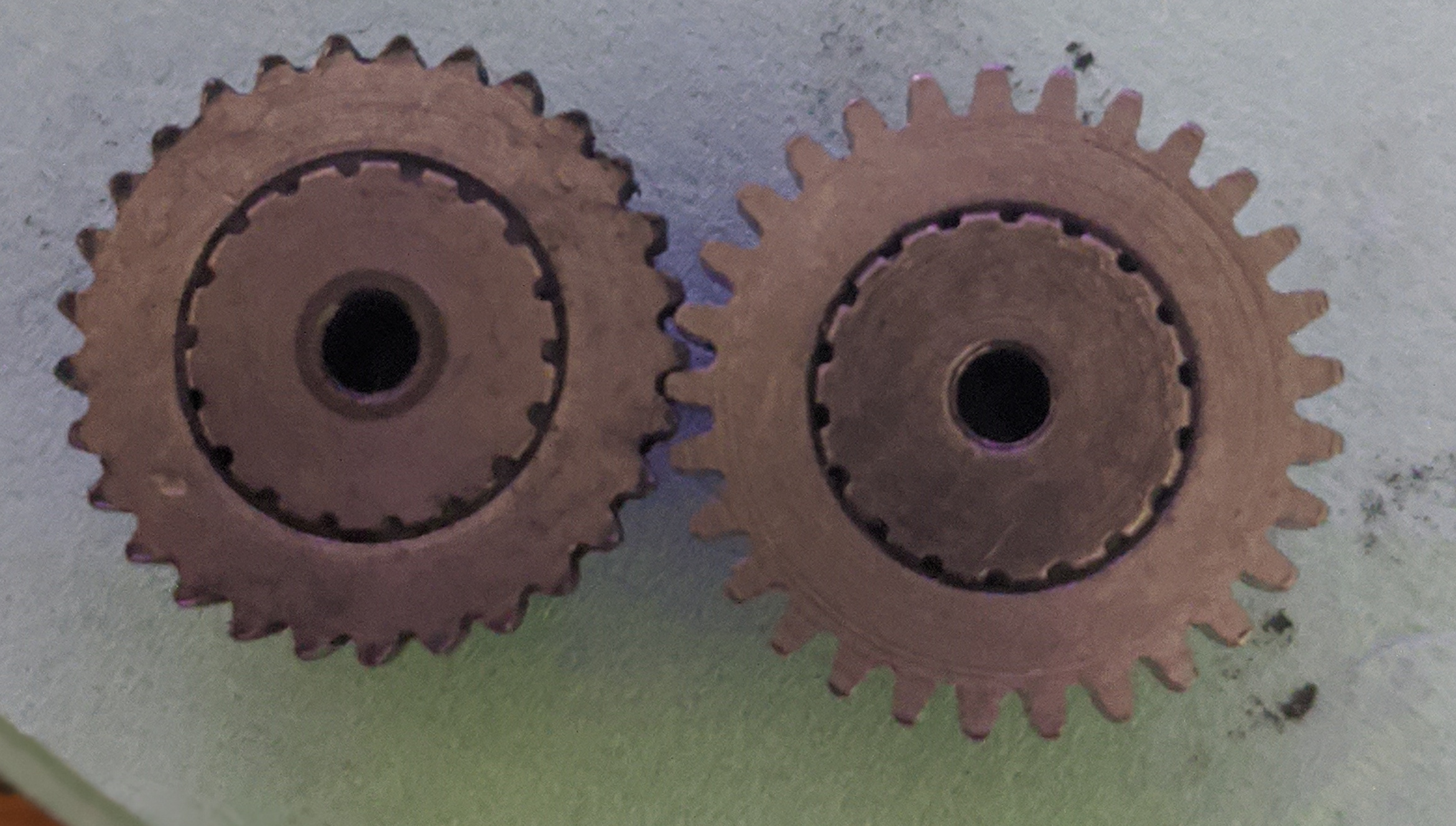
…the robot started to make popping noises. It had gotten stuck a few times and I assumed that, once again, the couplers had broken free from the shaft. I disassembled the bottom section to check the motors and sure enough, I could turn the right wheel backwards and it would ‘pop’. But I couldn’t turn it forward… and that concerned me. So I shown a flashlight at the motor’s shaft and turned the wheel backwards and the motor shaft moved with the coupler… so no slippage. However, this is a wormgear motor and it’s not supposed to be able to be moved (that’s why they are used in the Maslow… to support the sled when power goes off). The original maslow motors came with a particular gear made of plastic and its been known to wear out. I had bought some metal replacement gears when the motor manufacturer supplied some to Bar (the creator Maslow). I had only used one of the four gears to date so I opened up the motor and, to my surprise, the motor with the problem had the metal gear. I looked closely and saw that the gear was worn… so even the metal gear can wear out.
Hopefully it was mostly worn from use in the Maslow and not the robot. My design has the axle supported by two bearing blocks and the motor shouldn’t be carrying any weight…
But back to the voice control… It’s pretty awesome. I’ll demo it when the robot is put back together. I need to buy some degreaser and some grease because there’s metal shavings in the grease that’s in it right now. And I need to print out a new motor mount since I had to break the one off so I could get my angle grinder on the coupler and cut it away from the motor shaft (yes, the threadlocker worked REALLY well).
1 Like
Motor fixed… runs much better now.
The voice recognition is not perfect, but its not terrible either (also, the wake word can’t recognize the twin’s voice… guess its not trained on kids). In the video below, I had to tell it to go to base three times. First time it didn’t recognize the wake word, second time it thought I said to go to ‘banks’, third time worked. I also need a better speaker on it because its hard to hear it, especially the ‘beep’ when it recognizes the wake word.
I created four polygons (my ‘lab’, the hallway, the twin’s room, and ‘base’ which is a 0.5-meter circle in the middle of my lab) that are referenced to the map. The ‘brain’ software does does point-in-polygon tests to determine which polygon it is in and if it transitions from one location to another, it announces doing so. I must have a gap between the lab and the hallway because it enters an ‘unknown’ area when it moves through the doorway.
5 Likes
Looks like the video is private or something.
Forgot to hit save when I changed the setting. Work now?
1 Like
Sure does. That works great. That looks like it is picking good paths and executing them well. Nice work!
I discovered afterwards that the kinect wasn’t turned on, so the navigation was purely from the laser scanner. But the laserscanner doesn’t detect obstacles above or below its centerline, so I still need the kinect. I need to spend some time optimizing the installation of the kinect to make it stiffer, calibrate the IR camera to take out any fisheye, and then make sure it aligns well with the laser scanner. I think there’s some fisheye going on because last time I tried to align it, I could get it aligned with the center but off center was ‘off’. With the kinect as it is, it some times gets stuck in the doorway because the two laser scans aren’t aligned well enough and the lethal zone in the doorway gets too big.
Camera calibration is about half the work of perception. Hopefully someone has shared a good solution and you can just apply it to your setup. We used to wave a black and white checkerboard in front of our cameras to get measurements for the distortion. It was reliably awful on fish eye cameras. But it was good enough to drive a car with.
That’s the procedure within ROS. I think, in general, the kinect is pretty good as it uses low distortion lenses based upon what I read:
http://wiki.ros.org/openni_launch/Tutorials/IntrinsicCalibration
… but I’m trying to align two laser scans and calibrating the kinect might help eliminate the camera as a variable to deal with… because I have six other variables to optimize… the position of the camera (x,y,z) and orientation (y,p,r) with respect to baselink. If the transforms are off, then the whole thing is out of whack.
I would do as best as I could with the intrinsics, but then I would take a few bags pointing at the door from different angles, and try to just fudge the extrinsics until they aligned well enough in those cases. I do not believe it will be perfect in all cases, so just make the ones you care about right.
It’s a bit of “demo engineering”, but you get a pass because you aren’t training it in your house to go work in the mall.
2 Likes
 - Introducing the Killbots Scene (1/9) | Movieclips")
2 Likes
After a couple of days of mucking things up so much that the robot kept driving itself into a wall, I finally got it working again and made a backup copy of all the param files. What a painful last couple of days.
My findings are that the kinect located at the top of the support pipe with a tilt is problematic. Though the software I am using (depth_nav_too) is supposed to accommodate tilt, the adjustment seems to narrow-in the obstacles… for the doorway, the jambs become closer (opening narrows) so it gets too small for the robot to figure out how to get through it. If I have it level with tilt adjustment disabled, things line up pretty much perfect with the laser scanner, so I don’t think there is any camera calibration that will fix it… I suspect an error in the depth_nav_tools module, but the maintainer of it seems to be AWOL (I posted an issue about a bug that actually breaks his software and there’s been no response). I think the software, when it looks for the closest ‘depth reading’ in a particular column, doesn’t consider that the column I think needs to be ‘tilted’ depending upon how far off center it is… it just does a vertical scan of the image as if the image was level.
The other alternative is to do a voxel costmap using the kinect’s camera, but I’m running into trouble getting that to even work and it might just be too taxing on the CPU to process all the data.
So for the time being, I’m going to look at placing the kinect in the front, really low, just below the power port/front threaded rod support(printing a stand to raise that whole thing up). It won’t have a wide field of view, but hopefully good enough to avoid obstacles in its path.
Tf is supposed to fix all of that for you. You should be able to publish the transform from the kinect coordinates to the base_link and all the stuff found with the kinect gets published in the kinect coordinates. It requires all subscribers to read in the kinect data and see that it is in a different coordinate frame and then transform it before using it.
Downsampling the data, using bigger voxels, is a cheap way to make any of that processing faster. It is hard to make it work in tight spaces though. Your resolution needs to be fine enough to get through the doorways.
The depth_nav_tools, I think ignores transforms (is that possible?). You have to enter how high the kinect is, relative to the floor, and the angle its tilted. It outputs a laserscan thats parallel to the floor so I suspect transforms aren’t used.
As for the pointcloud, one time previously I tried to downsample the pointcloud and the downsampling module used a whole lot of CPU as well. damned if you do, damned if you don’t. But I’m running into other issues… move_base is reporting my sensor is outside the map bounds and the costmap can’t raytrace it… I found someone with a similar issue and they fixed it by raising the orgin_z to equal where the sensor is, but that didn’t work for me and I wonder if its just because the thing is tilted (though I did transform it properly) /shrug
Definitely. A lot of ROS code has “add tf” as a TODO for the future. It’s also common for libraries to not want to take on the additional computation that comes with something like that.
You could try to transform it yourself first. With a node that subscribes to the kinect message, creates an empty message, and then populates it with the points transformed into that new coordinate frame. That can be quite a worm hole doing it yourself. But you’ve surprised me several times so far.
Transforms are probably the hardest part of this stuff. It really can get hairy, and there are a bunch of answers that look right in 75% of the cases, but are totally wrong. Since it’s such a hard problem (and generally, requires linear algebra, at least a little, to solve) there are a lot of libraries doing it wrong. TF is supposed to help by making it easy for people to do it right, but it’s still not used everywhere.
I think its too deep of a “worm hole” to do.
Surprisingly, I did manage to get the pointcloud to work in a manner. It doesn’t seem the right way, but it works. In local_costmap_planner.yaml, I used the costmap_2d::ObstacleLayer plugin, not costmap_2d::VoxelLayer, and all the errors went away. I don’t know exactly what that means or what it will prevent me from doing, but I can navigate into the twins room and back. So not sure what’s missing from using obstacle layer vs. voxel layer. I also spent time aligning the pointcloud image with the laserscanner as well as I could and then shrunk my local costmap from 2.5m x 2.5m to 1.5m x 1.5m to help eliminate the floor as an obstacle when the camera shakes a little (floor tends to pop-up as an obstacle around 2m away sometimes).
Ran into a couple of glitches. First is that I discovered that if an obstacle appears on the local costmap that’s at the edge of the costmap and the global path passes through it, the robot will stop. Picture below:
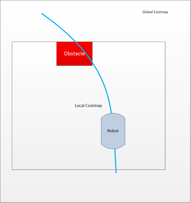
I would have thought the local planner could figure out to just go to the right of the obstacle, but apparently not. I tried a bunch of different settings and nothing would work. So I decided to add the kinect obstacle layer to the global planner so it would recreate the global path if an obstacle is detected. The robot then drove into a wall. Seems that recreating the global path too often can lead the local planner and the global planner to kind of start chasing/leading each other and then bad things happen. I discovered via googling that if I set the planner_frequency to 0 in move_base, the global path will be recalculated only if the robot finds itself stuck. That worked and in the above scenario, the global path would be created to go around the obstacle and the local planner then be able to avoid it… kinda…
When the obstacle is out of view of the kinect (because the kinect is high and looking forward), it disappears from the local cost map when the robot gets close to it and the local planner doesn’t really stick well enough to the global path, particularly during a curve portion of the global path, and the robot can bump into the obstacle. I plan to try to tweak the local planner settings to make it follow the global path as much as possible without losing the ability to get around obstacles in the global path on its own. I hope that works but if not, I’ll need to find other sensors to include to track very close-by obstacles that are out of the path of the robot (maybe go back to the sonar sensors, but limit their range).
Finally, the kinect point cloud seems to be a bit noisy I get these sporadic blips that create obstacles and then disappear. This makes the robot stutter a lot. I think I’ll need to do some kind of filtering on the point cloud data after all. Maybe filtering by reducing the data points would effectively cancel out the noise. Hopefully it can be done without too much CPU usage.
My Rock Pi X sample is supposedly to be delivered today (can’t really trust the USPS these days to do what they say). Will see how it works.
1 Like