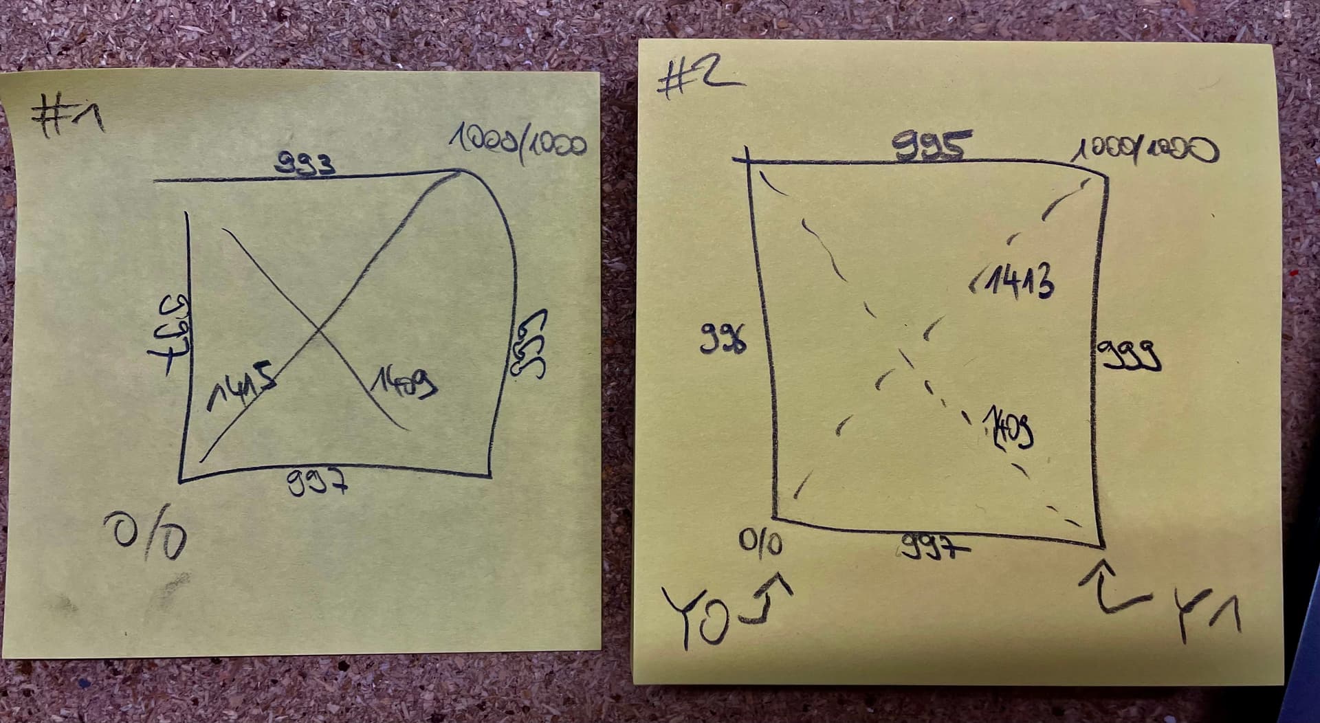
In my 1x1m LRv4 build I am trying to calibrate squareness for over two days without luck, meaining a diagonal difference of less than 5mm over 1m.
However, after revisiting the belt steps calibration step, I just noticed that when asking the machine to move 1000mm, the left side (“Y0” on my machine) actually travels 994mm, while the right side travels only 981mm. This is with the pulloff values back to stock, i.e. 4mm for each Y motor.
What I checked:
Belt tension on Y0 and Y1 seems even (and not too tight).
Measurements have been identical via laser and tape measure.
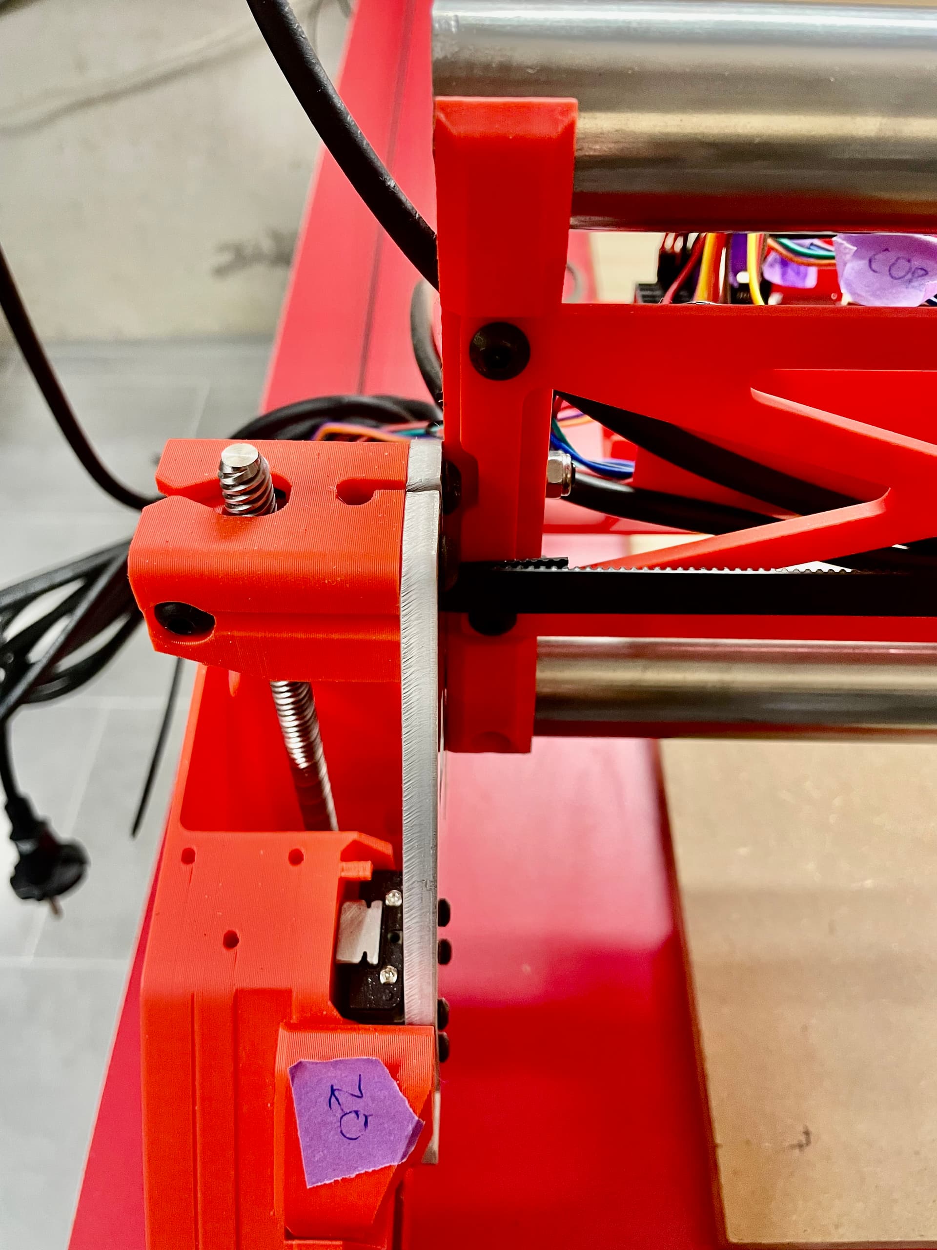
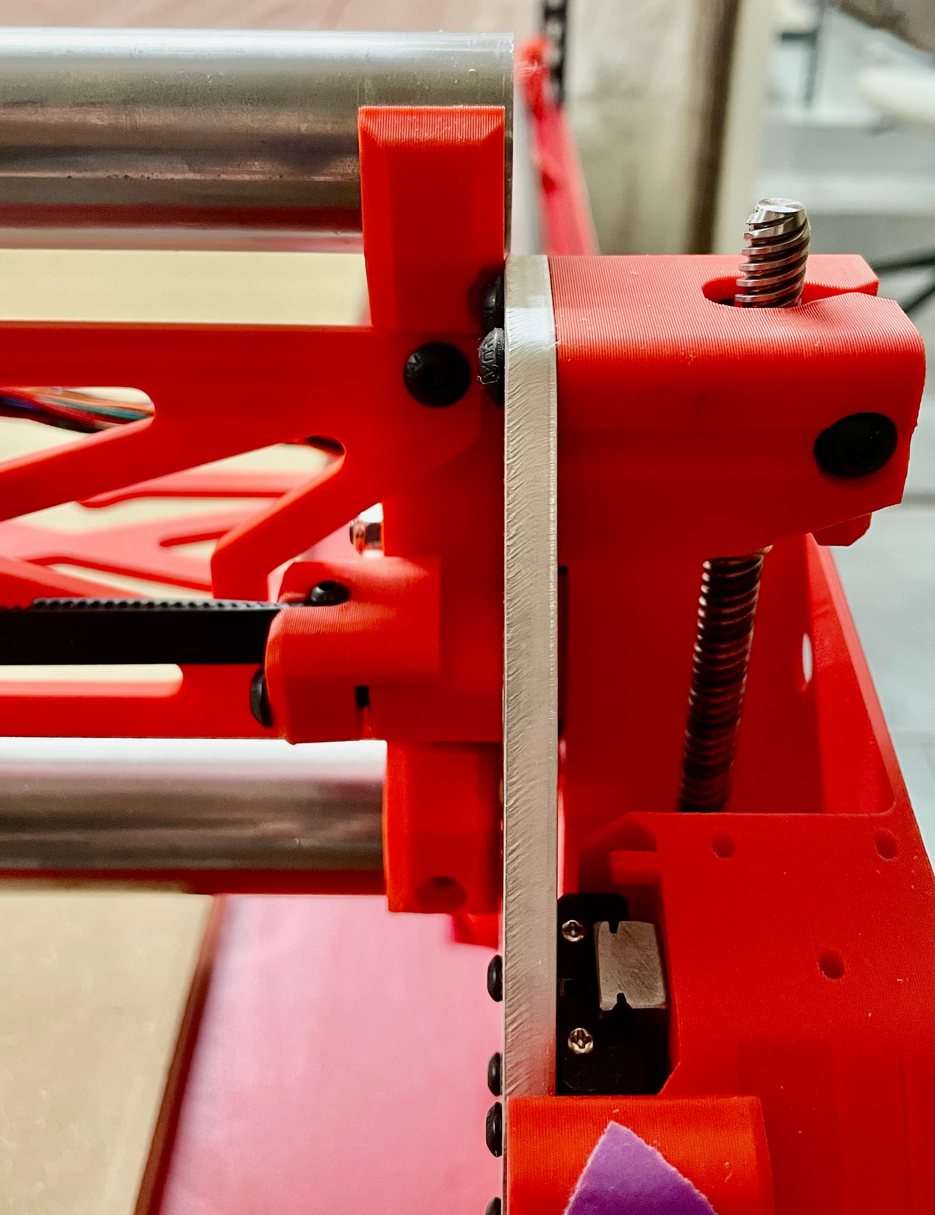
What I also noticed and might be related: The X beam is not 100% parallel to the belts, see picture below.
What could be the cause of this unevenness and what a potential fix?
I agree with @azab2c . The gap you’re seeing in the belts is likely caused by the inconsistent moving, not the cause of it. Since one side is moving less than the other, the gantry becomes angled, so the front and back will be different distances away.
I would check grub screws first and then belt pitch. To check belt pick you’ll want to line the belts up next to each other and see that all the teeth align.
Miscalibrated tension for me leads to errors in the 3mm range, not 13mm for sure.
Thank you for the suggestions! Belts look fine and teeth match, grub screws are fixed good.
I noticed the right side can be moved by hand with little effort even when the steppers are powered, while the left side cannot. What could be wrong there? I guess this is related to the problem.
I have some more troubleshooting questions:
Can you post the output of $SS from the terminal? That will help evaluate config related issues.
On the mechanical aspects, double check that the tubing in your X axis beam does not protrude beyond the end braces at any spot, if it does it will cause camber/caster issues for the machine.
You can post pictures of the ends of your beam or better still also take measurements of the distance between the YZ plates on each side of the beam. If they’re not equal then you have an issue to fix there.
We’ve seen poor quality (e.g. aliexpress) belts vary in pitch by a percent or more. Belts from V1E have been tested more and observed to be more accurate and precise, without having to pay premium prices for premium branded belts.
Depending on where your Belts were sourced from, check out…
The accuracy and precision behavior you’re seeing for repeated tests can be helpful with identifying correct thing(s) to focus on fixing/tuning.
Sure, $SS shows the text pasted below. My config is simply the version from github with only max_travel_mm changed for my build and soft_limits set to true.
Re. the mechanical aspects, I measured the total span of the X beam on both “feet” sides today with 1mm difference and just now only between the XZ plates of also 1mm, which I considered ok (let me know if not). On the left side, I can fully insert a piece of paper between the lower rail and the XZ plate, on the right side the paper goes in about 50% of the way compared to this, pictures:
This has not been thoroughly tested. You should revert back to 3.9.9. I’m not saying it’s the source of the problem, but it certainly muddies the waters.
Turns out, you are right about the grub screw, @azab2c! The second one on the Y1 axis motor was very loose. After tightening this and all others just to be safe, I can no longer move the Y1 axis by hand while the steppers have power. Thanks much!
Measuring everything again twice with a laser still leaves me with a 2-4mm difference on the Y travel over 1000mm (as well as for X).
3mm difference between Y0 and Y1 is is not entirely unexpected. Many people would just live with that (0.3% error over 1000 mm). If you want to increase the accuracy of your build (“chase zeros”), the best way (IMO) to compensate for that is NOT to adjust the steps.mm, but to adjust the belt tension.
Compare the distances of both Y motors to the distance expected. If both motors are somewhat shorter than expected, you can tighten the belts to increase the distance/tooth on both. Similarly if one motor travels less than the other, you can tighten the belt on the shorter travelling side to bring them closer to equal.
The pitch of the M3 screws is 0.5mm/thread, so two full turns of the screw should adjust your total travel over the entire belt length by 1mm (better to measure distance over the entire belt length, rather than just 1m IMO).
Obviously you don’t want the belts “guitar string tight”, but increasing the tension by a few mm over a long distance should be okay (IMO).
But I would also start to suspect measurement errors, based on the difference in X travel in different gantry positions. X distance is a function of only one motor travelling, so any differences show an inconsistency that is either a build issue (loose grub screw, looseness in the core, etc.), or a measurement error.
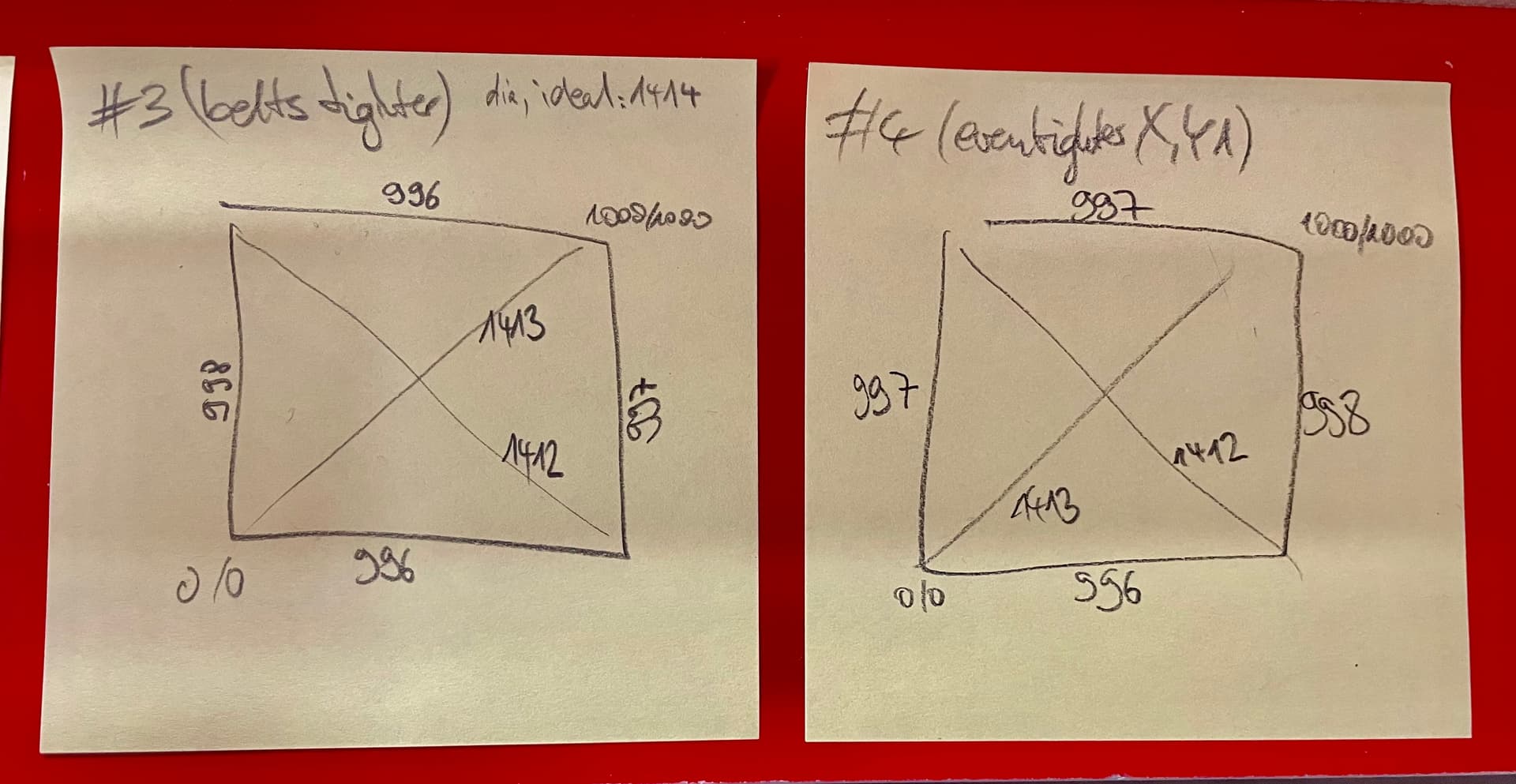
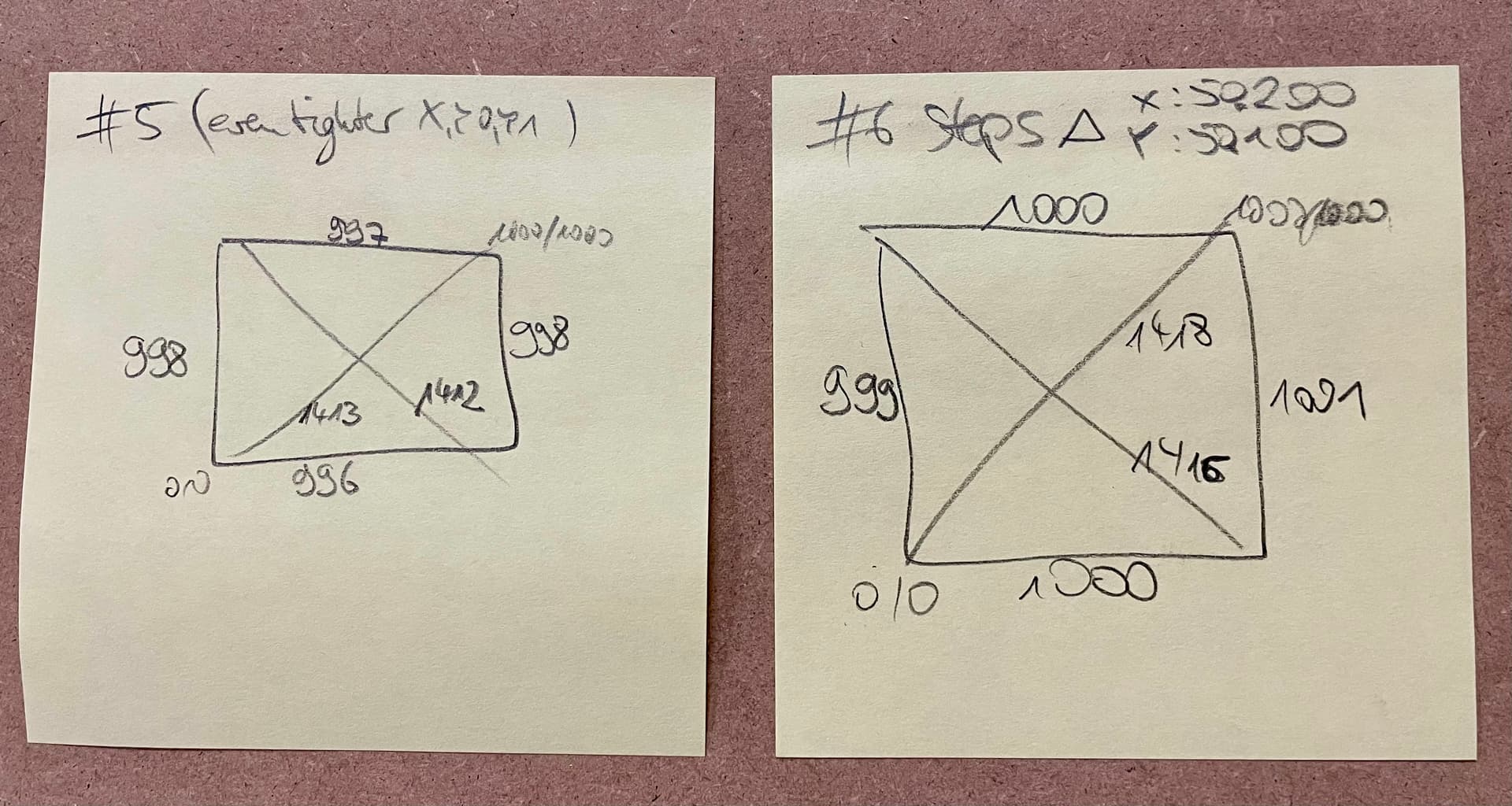
Thanks much, @Bartman! I have tightened the belts a little. Now my diagonals are only 1-2mm from the mathematical ideal value (1414mm for 1x1m working area). I will leave it at this for now.
@uu3ndcp are you considering tweaking Y axis steps/mm to bring the 997mm and 998mm closer to 1000mm ?
I don’t think we can set steps/mm for the individual motors, even so, splitting the difference and calibrating as is they’re bot 997.5mm should get you closer to actual motion of 1000mm
I’m puzzled as to how X distance at front (996mm) and back (997mm) can vary
Increasing the belt tension further resulted in no measurable improvement and I also do not want to tighten the belts even further to avoid damage.
Modifying the steps/mm helped for the last millimeters. I suspect the remaining minor differences to the ideal values (1000mm for the axes and 1414mm for the diagonals) to be measurement errors - same for the previous and remaining 1mm differences between sides.
With this, I am happy for now and will (finally, after what feels like a year of taking measurements again and again) move on to Z leveling. The 0.8mm difference there is hopefully resolved more easily
EDIT: Z levelling was a breeze. I am now at a Z difference of 0.1mm, which is more than fine for my use cases.