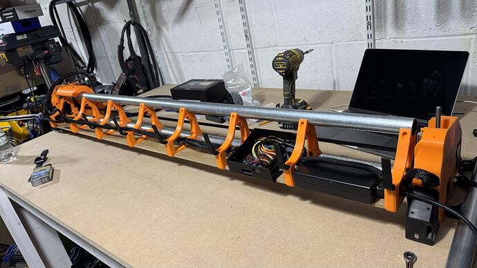
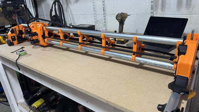
LR4 in Crowthorne, UK

Hello everyone, as I promised some colleagues on the forum,
I’ve decided to start a new thread here to document my process of building the LowRider CNC v4 machine.

First, I want to thank Ryan and his testing team for their hard work in developing this new version. I also want to thank you all for following along and encouraging me to share the excitement I’m feeling as I build this machine. I’m not the best writer, but I’ll try to express myself mainly through pictures and keep the words to a minimum.

A little about me: My name is Igor, I’m 39 years old, and originally from the Republic of Moldova. Seven years ago, I emigrated to the UK with my family. I’ve been working as a carpenter since I arrived in the UK, even though I originally studied radio mechanics (a profession I’ve never worked in, but still enjoy). After finishing my studies, I got into construction and have been working in the field ever since. I’m currently studying Mechanical Engineering and Design and also run a small 3D printing business where I produce jigs for carpentry, particularly for different types of locks.

Now, onto the main topic.
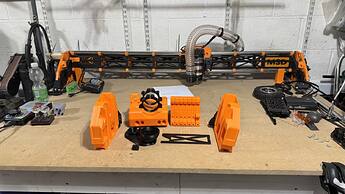
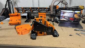
After version 4 of the LowRider CNC was released, I quickly reviewed it and began printing the parts. Yesterday, with some free time after work, I started disassembling my LR3 and moving the components over to the LR4.

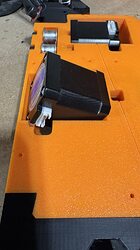
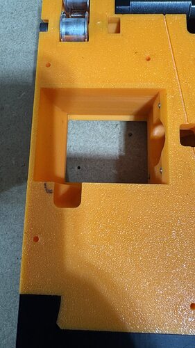
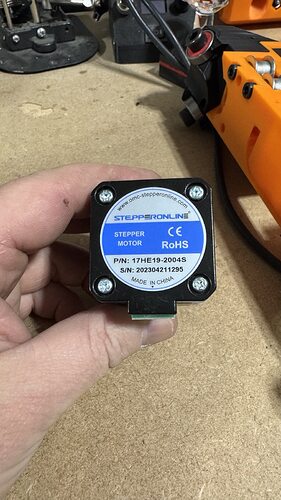
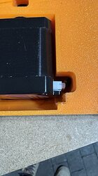
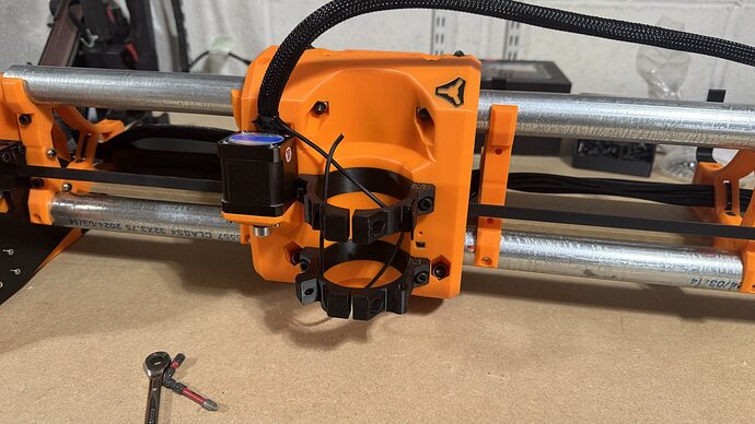
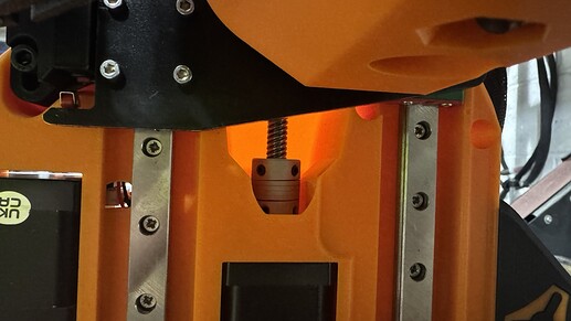
That’s when I discovered that the motors I used in my initial assembly don’t quite fit in the new design—probably because they’re from a newer model, but I’m not entirely sure.


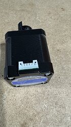
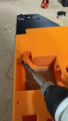
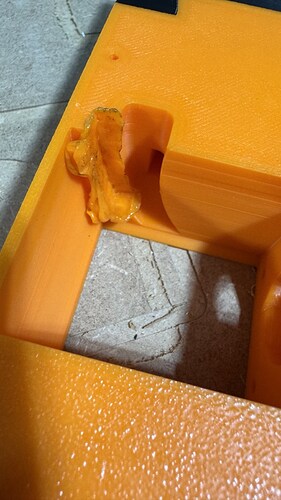
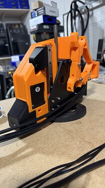
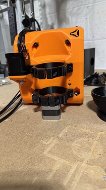
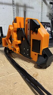
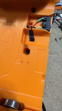
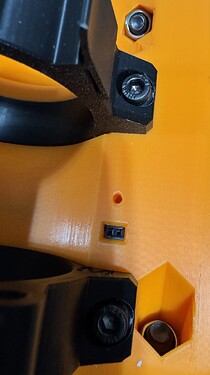
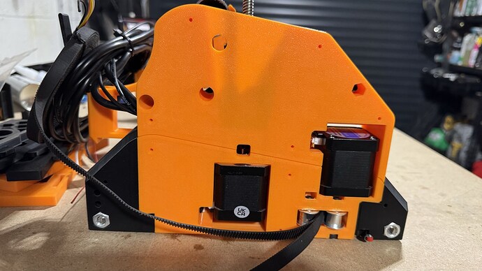
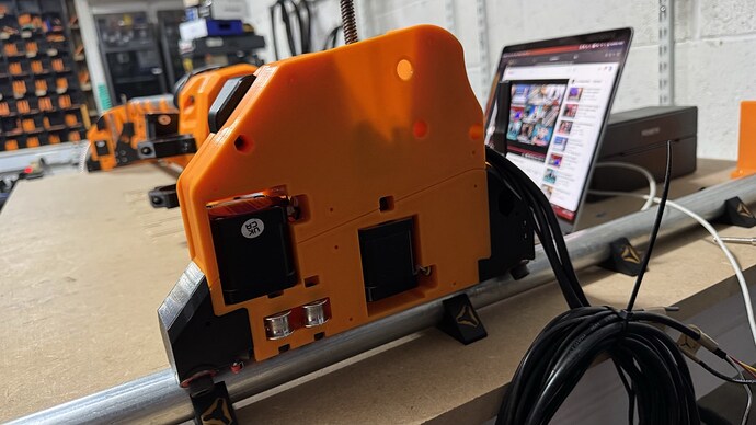
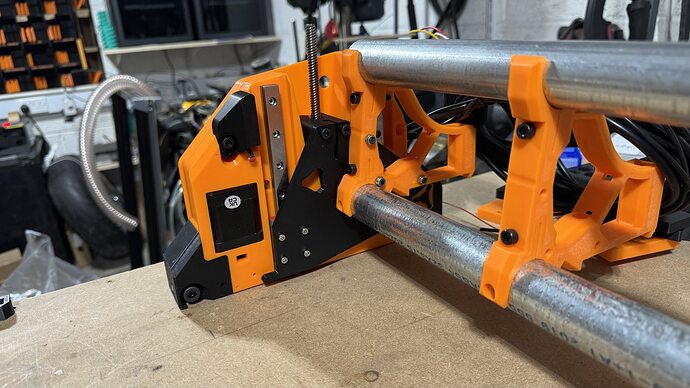
As you’ll see in the pictures, I used motors with connectors on the body because I wanted a cleaner look without exposed cables. I also like building things that not only work well but look good, too.


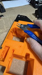
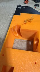
Since I didn’t plan ahead for the space needed to fit the connectors properly, I had to make some adjustments. Using a soldering iron, I carefully melted and leveled the plastic to create enough room for the connectors and align the motors in place.

I’ve already shared this issue with Ryan, and he’s up to date on the situation. I sent him pictures, and he said he’d make some modifications that I’ll test. If everything works, he’ll release updated files with the new version.

So far, I haven’t made much progress on the build, but I’ll keep you all posted as I move forward.
14 Likes

I love the color scheme. My LR3 was orange and black, but yours is a LOT more stylish. Great look.

3 Likes

That is my favorite method for post-print modifications and repairs!

2 Likes

Hello everyone,

I finally found some time to continue working on the LR4 build. Unfortunately, I still haven’t received the package from the US—something went wrong, and it was returned to Ryan. I’ll just need to be a little more patient, but it’s no big deal; everything will work out. To avoid wasting time, I decided to print the XZ plates so I can keep assembling the CNC.

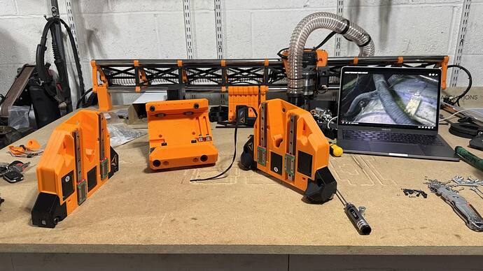
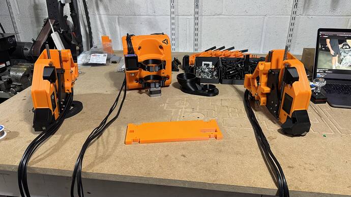
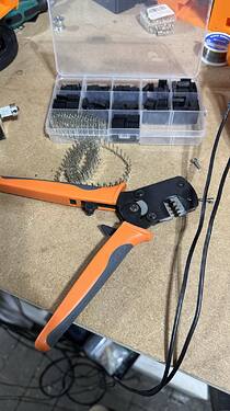
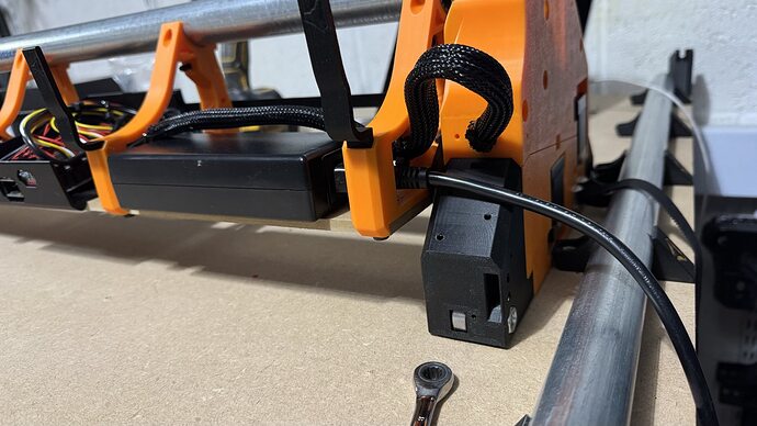
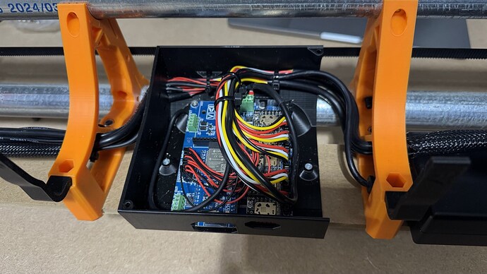
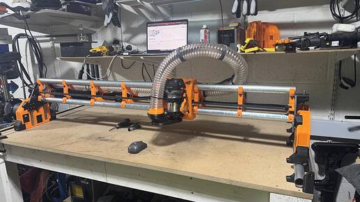
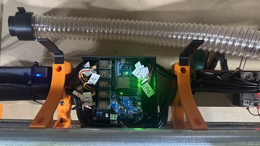
I’ve pretty much assembled all the main parts. The motors are connected with their cables, and I’ve installed all the limit switches as a precaution. I’m not sure if I’ll use them all, but I figured it’s best to run the cables now while I have the chance.

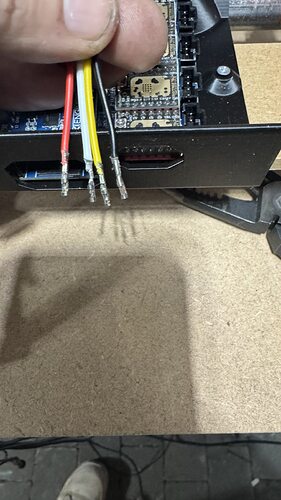
When assembling the core, I decided to install a small connector for the Touch plate. This gives me the option to easily disconnect it from the core if needed. I’m not sure if I’ll use it either, as I usually adjust the Z-axis height by eye, simply lowering the cutter until it touches the material. But again, I’ve decided to wire everything up just in case.

Due to limited space in my garage, I’ve set the working area to 1220 mm on the X-axis and 610 mm on the Y-axis. Usually, the X-axis is shorter and the Y-axis longer, but I chose this setup to give myself the option of working with a larger table in the future that can accommodate a full sheet. Personally, I find it more comfortable when the gantry is in front rather than off to the side.

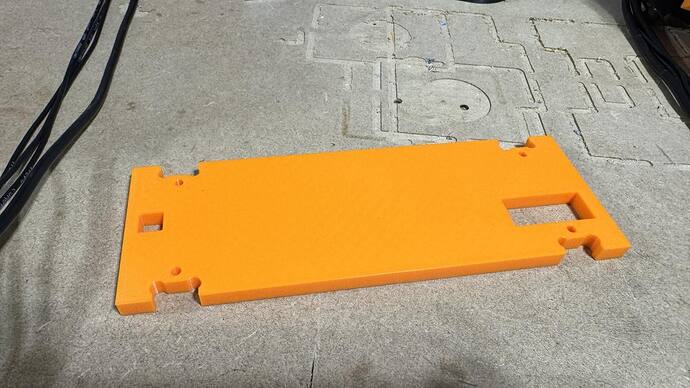
Since I won’t be able to cut the strut plates with the CNC machine due to space constraints, I’ll cut them manually. First, I’ll use a plunge saw to cut them to size, and then I’ll use a hand router with a flush trim bit to carve out the pockets, using a template I drew and printed with my 3D printer.

That’s my progress so far. I’m looking forward to receiving the package so I can connect all the components to the controller. I hope you’re interested in following along with the build process, and I wish you all the best with your own LowRider projects!

6 Likes

Dude, the orange and black is just fire! One of my go to color combinations! Yours looks fantastic!!

2 Likes

Nice build!

The old machinist paper trick also works well.

  1. Place a piece of paper between the cutter and your workpiece.
  2. Move the paper back and forth with your fingers as you slowly jog the Z down. Stop when the cutter lightly catches the paper.
  3. Zero Z.
  4. Move outside of the workpiece to a clear spot where you have clearance under the bit.
  5. Move the Z down by the thickness of the paper.
  6. Rezero Z.

You can get pretty fast with practice and it works a lot better than eyeballing it especially when your eyes start to go bad. :grin:

Have fun!

5 Likes

The z probe is extremly helpful if you want to use multiple bits on the same job

3 Likes

The colour scheme is really, really nice. Regarding the strut plates I made a video, explaining how you can cut them anyway. :slight_smile:

2 Likes

Thank you, Mate, yes I remember that video, you already answered once, and that is clear to me, I am unclear on how to do the path section in the software. Can I ask you when you will have time to make a short video on how to do the path I am sure it will be useful not only for me. Thanks.

I have a screenshot two posts down. This should help. You set the toolpaths manually with engrave. :slightly_smiling_face:

Not going to have time to do a video about that, I guess. Will see whether I can do it though. :slightly_smiling_face:

2 Likes

I just found this thread. From what I understand that the modifications are in process. Thank you so much. Excellent post!

Hello everyone,

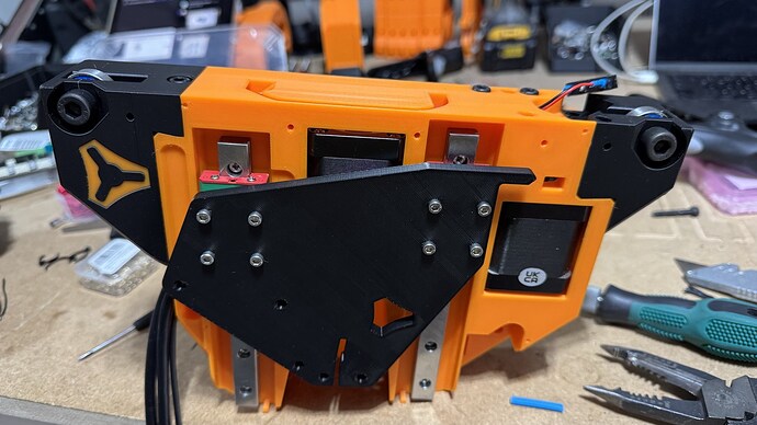
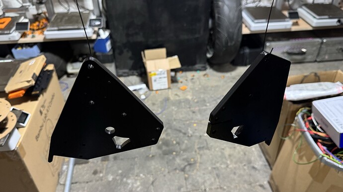
I apologize for the long silence—it’s been a while since I’ve written an update. Work and university have been keeping me very busy. Fortunately, I managed to carve out sometime last weekend to work on the LowRider CNC. In the meantime, I also received the package from Ryan containing the aluminium plates for the XZ axis. To maintain the black-and-orange colour scheme I chose earlier, I decided to paint the plates black to match the printed parts.

Since I know Ryan is super busy, I took it upon myself to modify the XY blocks to address the issue I described in earlier posts regarding the lack of space for the motors. To do this, I converted both STL files (min and max) into solids using FreeCAD—it was the only software that could handle the conversion properly, as Fusion 360 kept throwing errors. Afterward, I made the necessary adjustments using SolidWorks. While my modifications aren’t perfect due to my limited experience, I think they turned out pretty well.

I’ve also made progress on assembling the CNC. Most of the main components are in place, and I’ve connected nearly all the cables to the motors and limit switches.

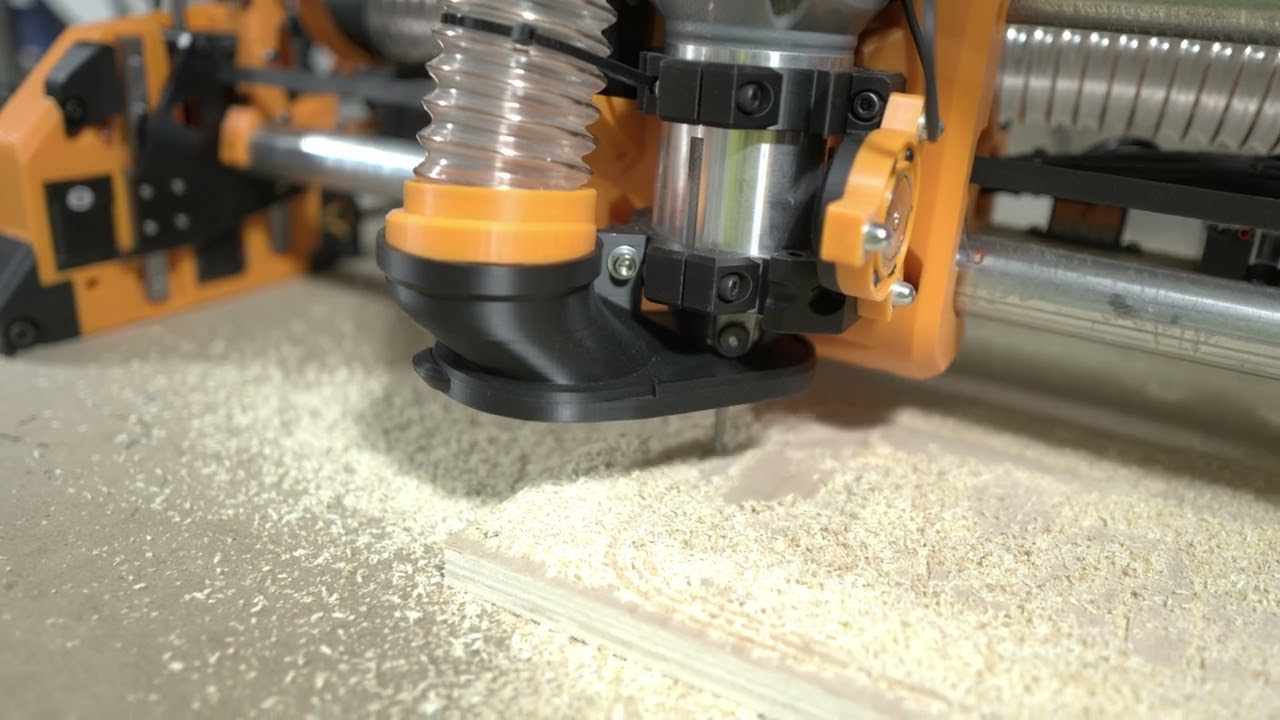
My next steps include installing the router and figuring out how to control it through G-code commands, so I can turn it on and off programmatically. Additionally, I’m planning to add a laser module to the CNC. I have an 80W LASER TREE module that I’d like to mount using the KINEMATIC Tool-less Quick-Change Accessory Holder by DOUG from Design8Studio:
LowRider V4 CNC Kinematic Tool-less Quick-Change Accessory Holder.

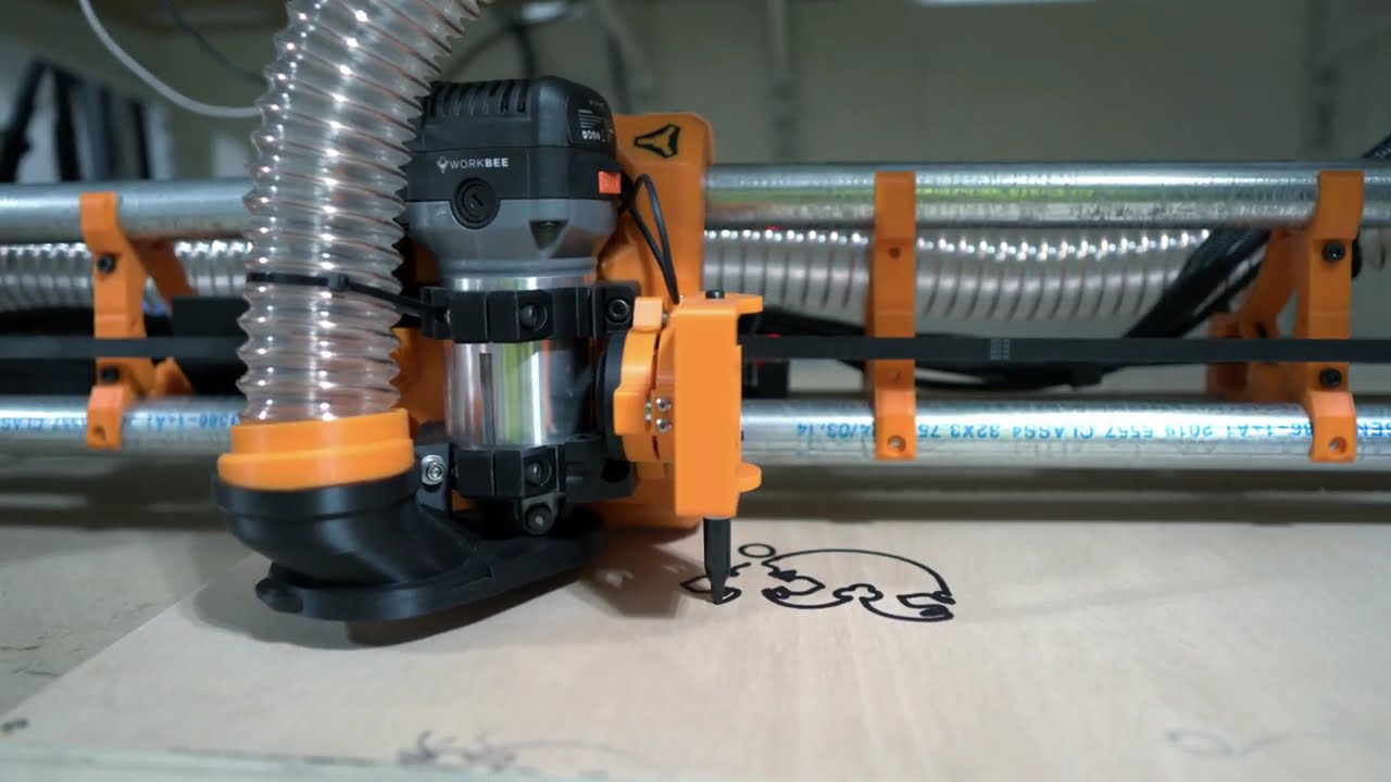
There’s still plenty of work to do, but I hope to complete the setup soon and draw the crown (and more). I’ll keep you all updated as I make progress.

All the best,
Igor

5 Likes

This looks really awesome. Maybe there is glow in the dark paint I could use on mine… :thinking:

If you ever have problems with the connection to the Jackpot, remove the cables from the top of the ESP. I think it is recommended to route them under the board or around it. :slight_smile:

Glow-in-the-dark paint sounds like a fantastic idea—it could add such a unique touch to your build. If you try it out, I’d love to see how it turns out! :blush:

As for the connection to the Jackpot, that’s a great tip! Routing the cables under or around the board makes a lot of sense to avoid interference. I’ll definitely keep that in mind if I run into any connection issues. Thanks for sharing the advice!"

1 Like