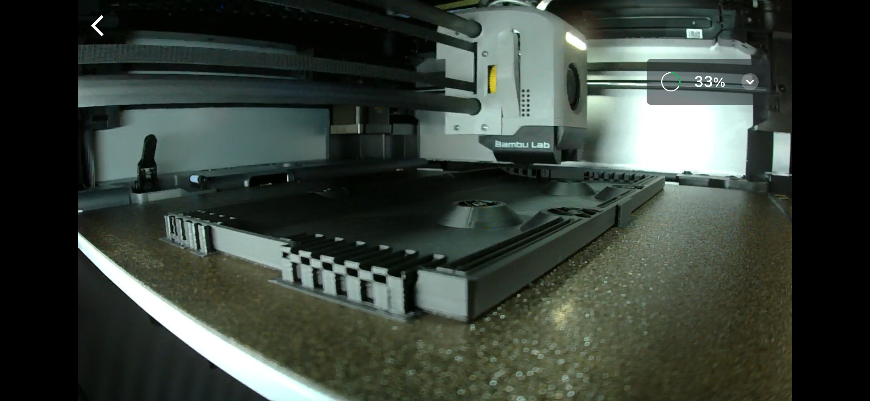
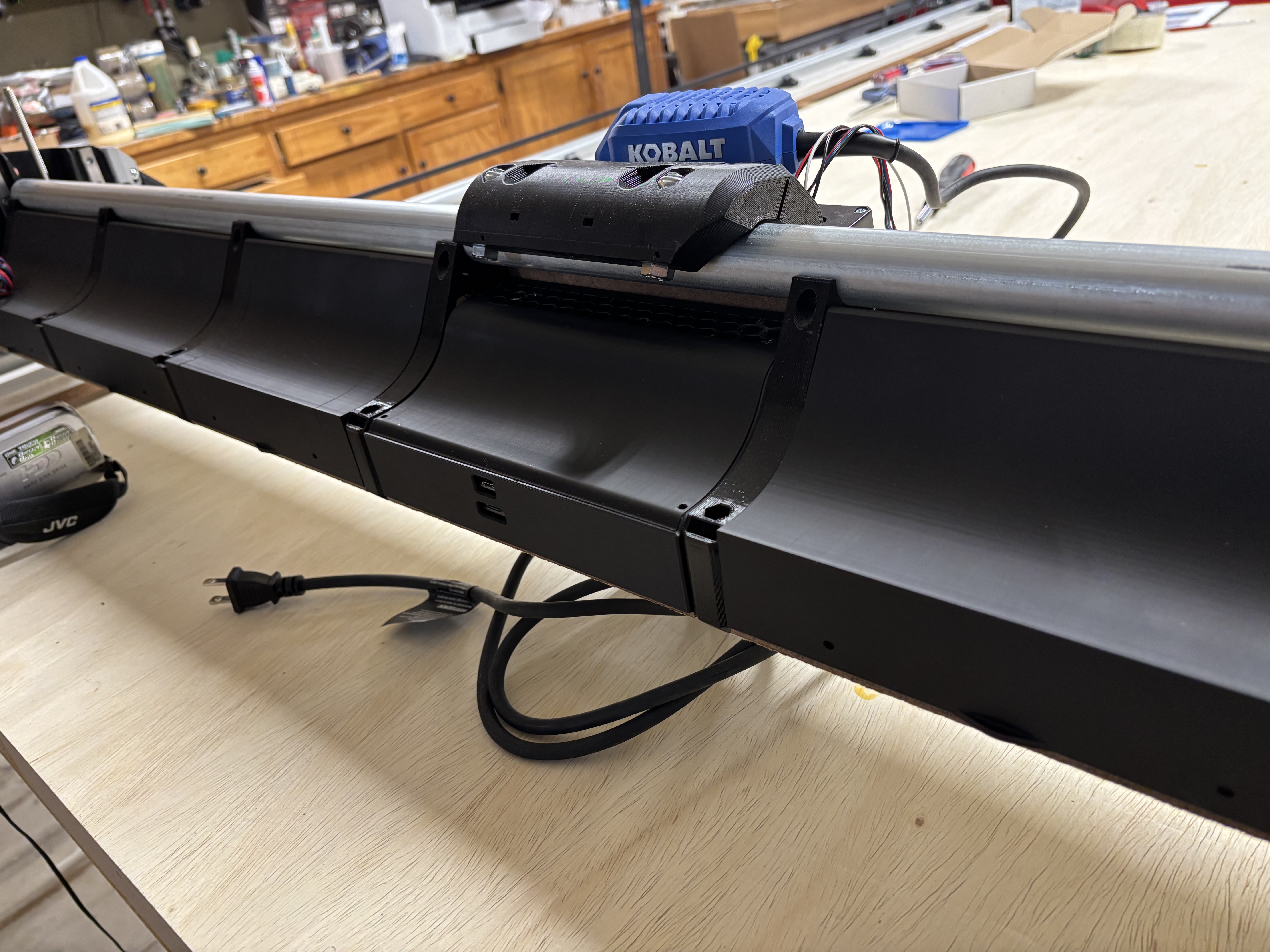
That is awesome. I downloaded it and then I learned how to turn it into a solid using fusion 360 and then I learned how to slice the body and then I extruded the distance that I needed back to the middle part roughly the same on each side so it ended up being 209.55 mm wide, which is what I needed based on the Doug covers I printed.
I first tried to scale it along the X, but then realized it was changing the mount for the board so I knew at that point I had to cut both ends off and extrude them back. Save it as an STL and now I’m printing
I did almost the same thing, only using 3D Builder (which I’m not sure you can get anymore) to edit the STL directly. Now I think about it I wonder if you could make all the modifications needed using plane cuts in prusaslicer…
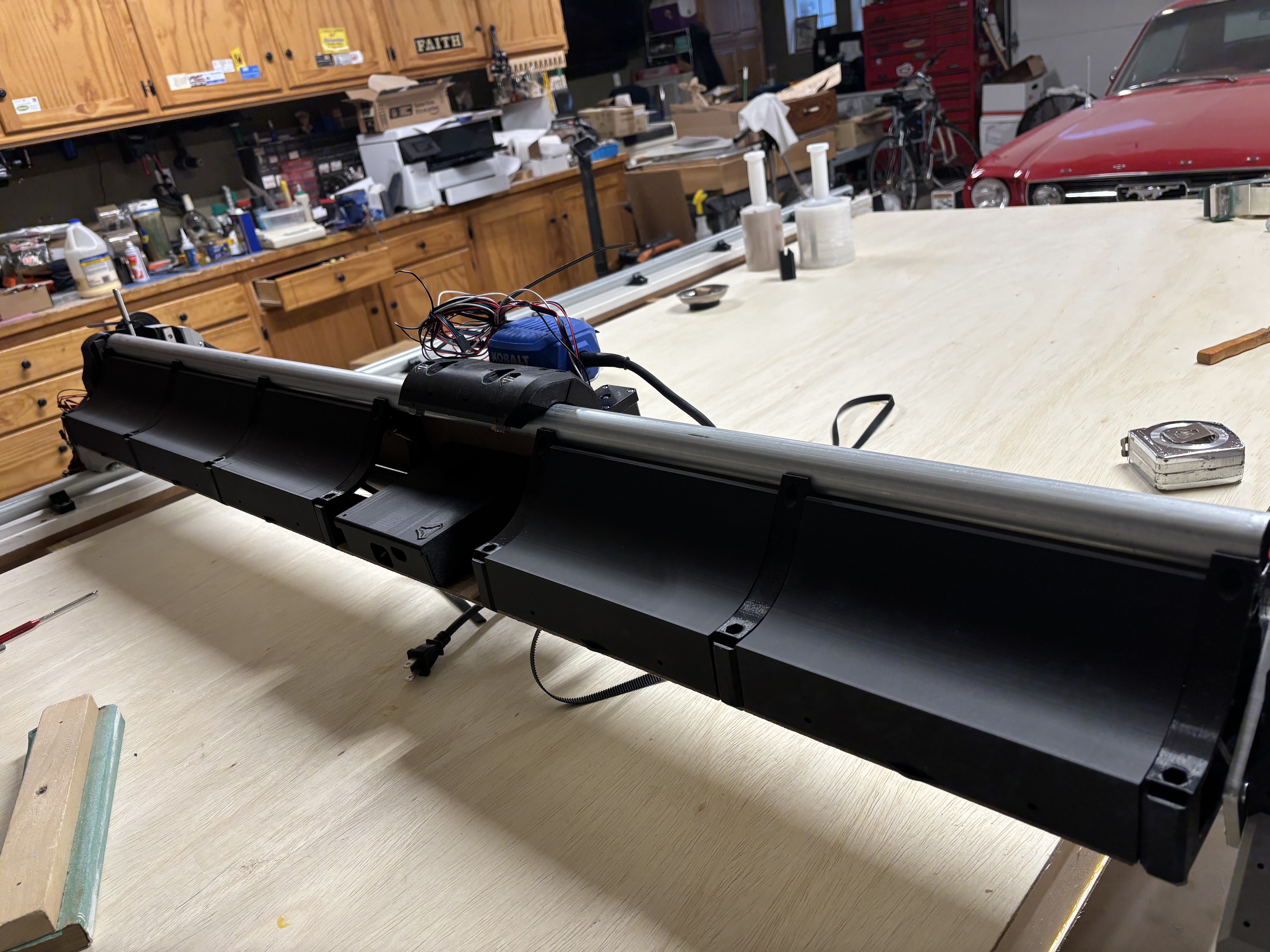
I also had to drill a few extra holes to run my cables in (I’m using the 3 holes in each strut to run 4 core cable through) so it’s a bit butchered but the lid hides all my sins.
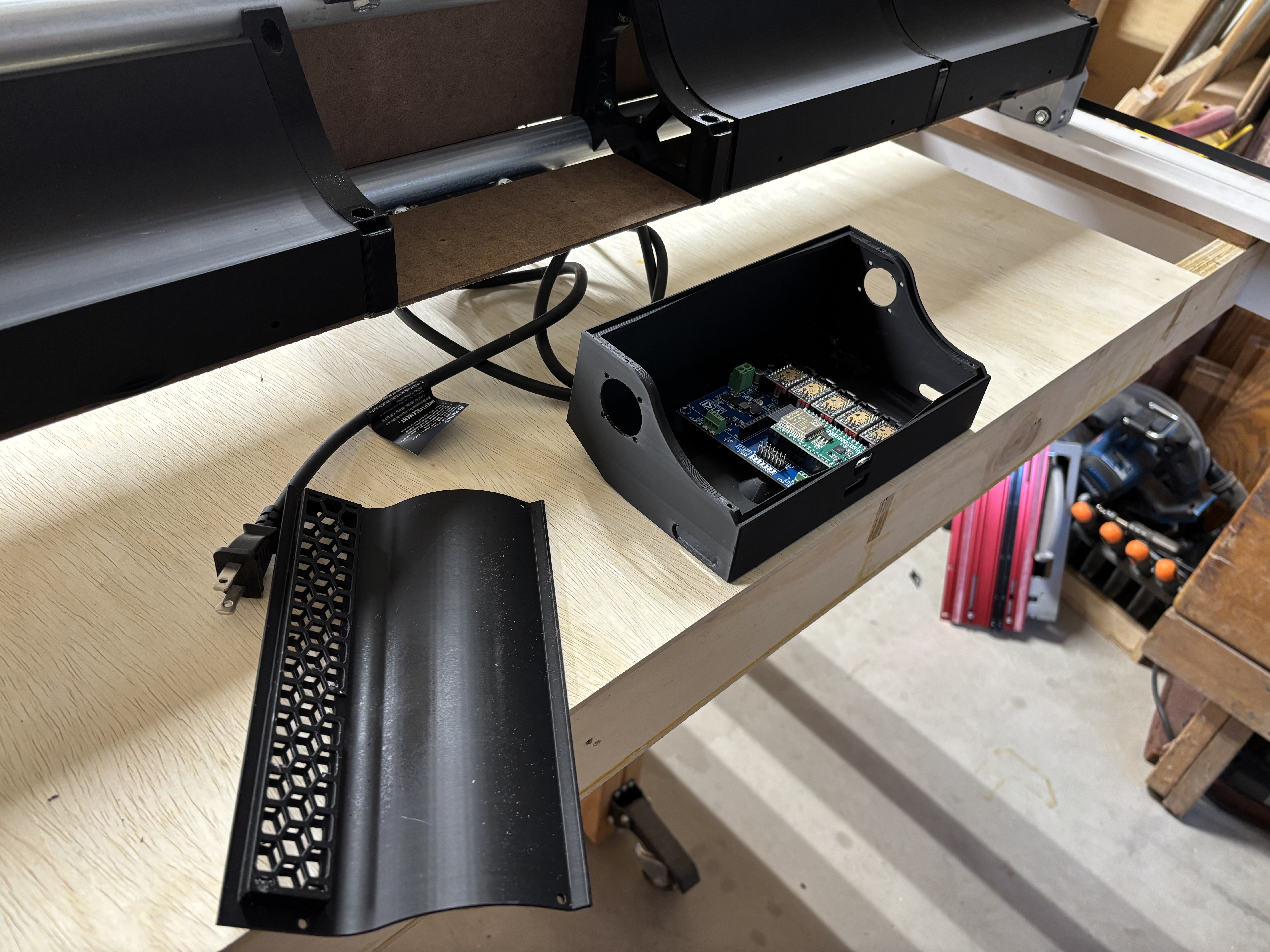
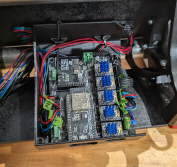
I think there’s just enough room in the box for my laser control board as well. That’s the next job once I get time to go back to it.
I really really like those covers, but please be certain there is lots of room to move on them. If they are a snug fit chances are very good chance they will bend your beam toward the front.
These are pretty loose but. I will go back and double check. The nubs that are inserted into the braces stick out just a tad, but the hole they seat in can be dug deeper so there is no pressure (did this by accident removing bottom layer as they are printed on end). One is so loose it won’t stand up open.
So while I was working (real job) I decided to print out Doug’s tie-downs and template so they would be ready when I get off work. If y’all decide to do the same, just remember you need one tie-down per door…and ONLY one template… not 6 of them
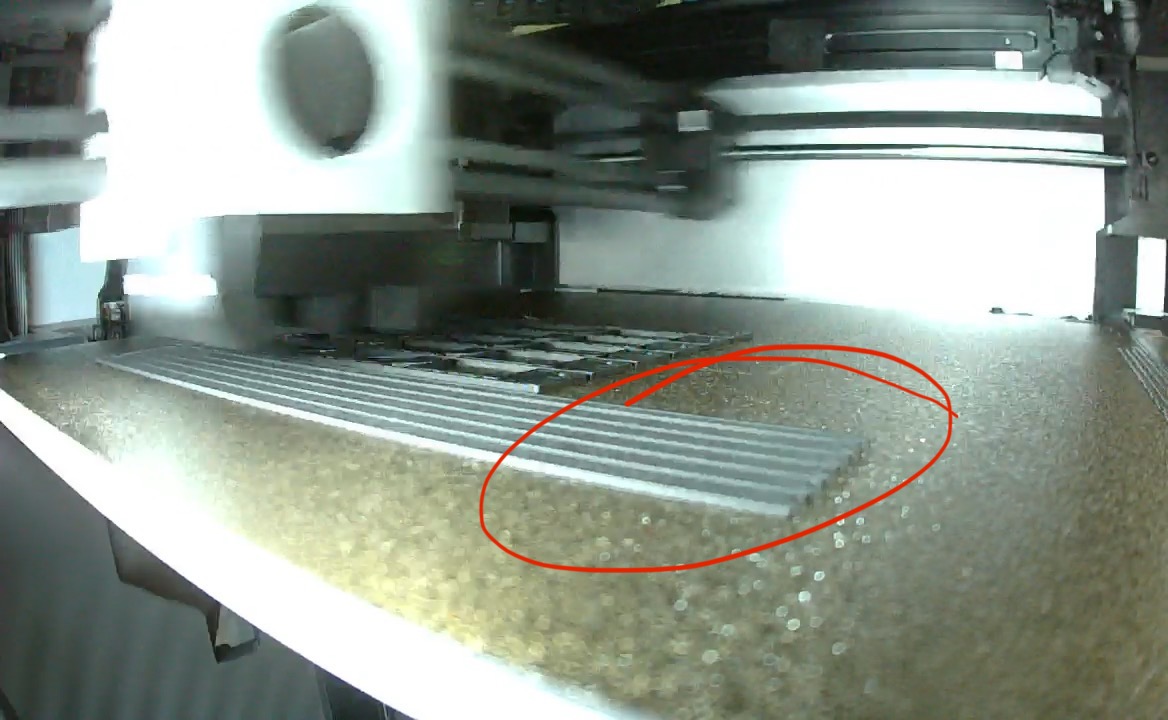
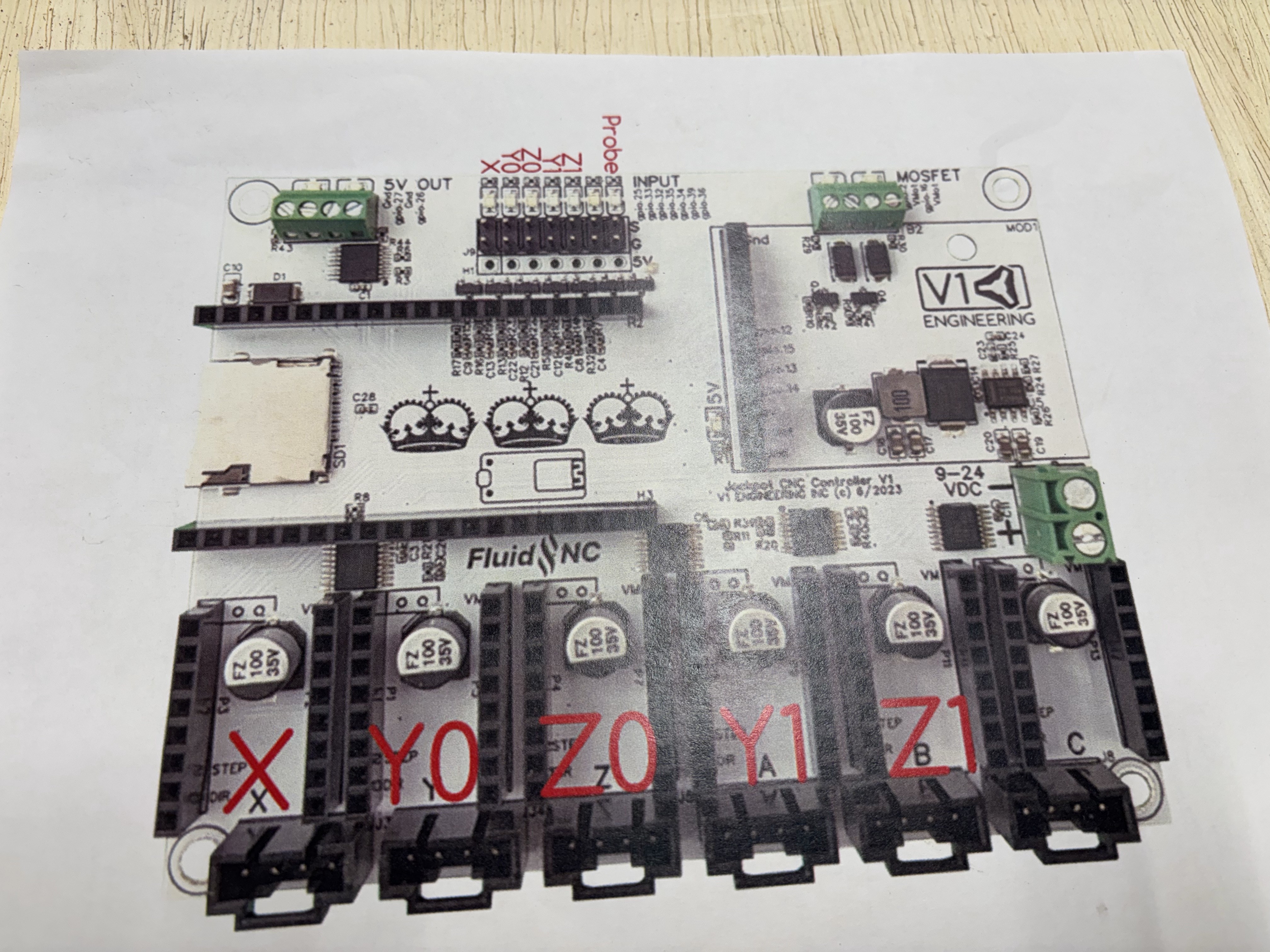
Well, first off - Happy. And Prosperous New Year to all. It sure was a busy week last week with Christmas traveling and all, and this week we’re headed out once again. But this afternoon, I was able to connect all the wires (preliminarily that is) just to make sure things could move. Of course at first the Y0 and Y1 were moving in opposite directions but that is to be expected I have come to accept.
The gantry went all the way to what I assume is the front when I homed the Y. So I think that was a good sign. The X homed to the non rail size and the Z homed up to the top until it hit the stops.
Please chime in if this is really off.
I noticed when I’m logged into the FluidNC as wifi, it keeps dropping. That would be bad during a job. Wifi works just fine otherwise (yes, I disconnected the ‘connect auto’ to my wifi) before loggin into FluidNC. I’ll need to explore that further.
That’s all for now. Not much is gonna happen until I return from New Years Vacation.
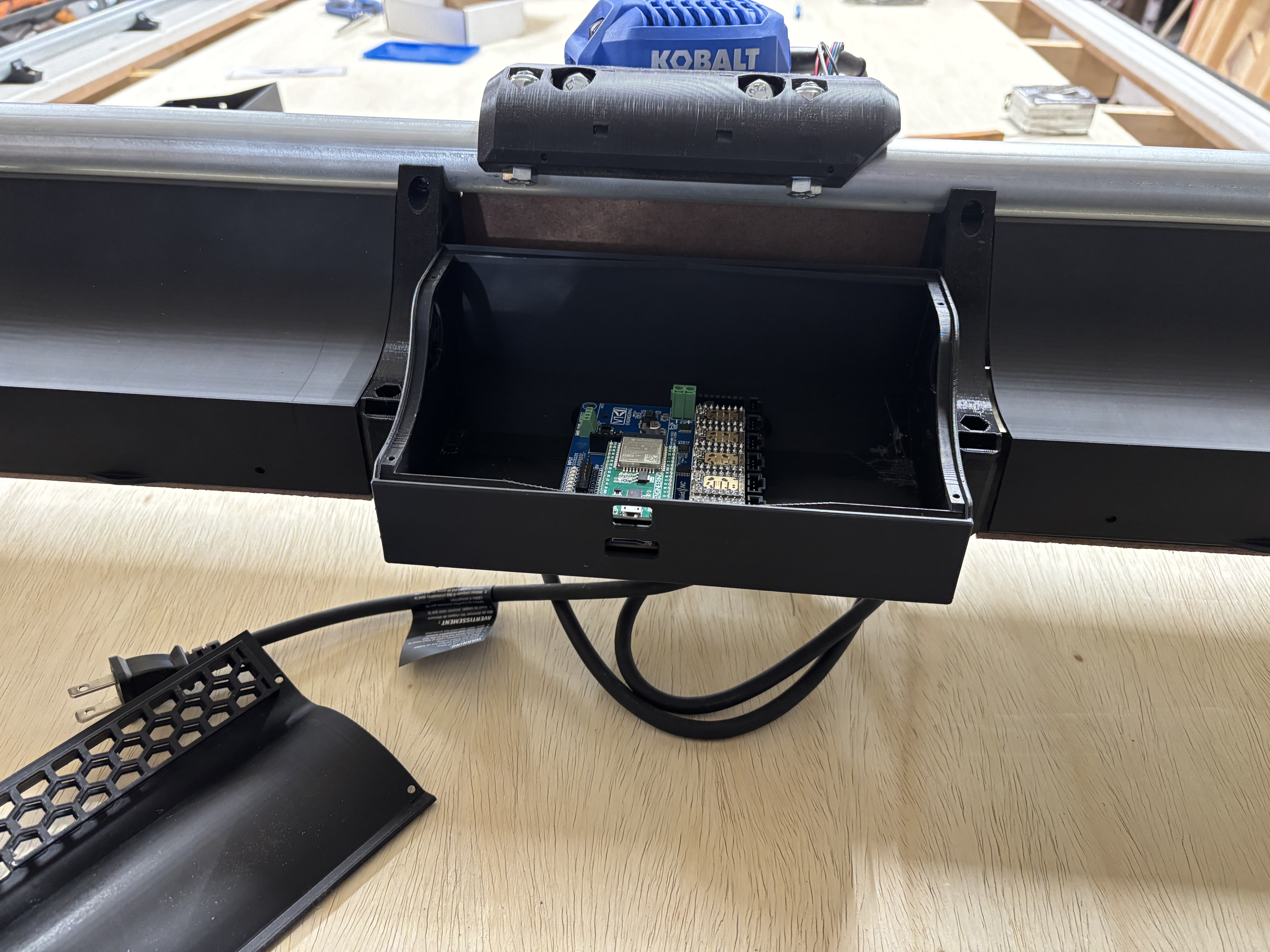
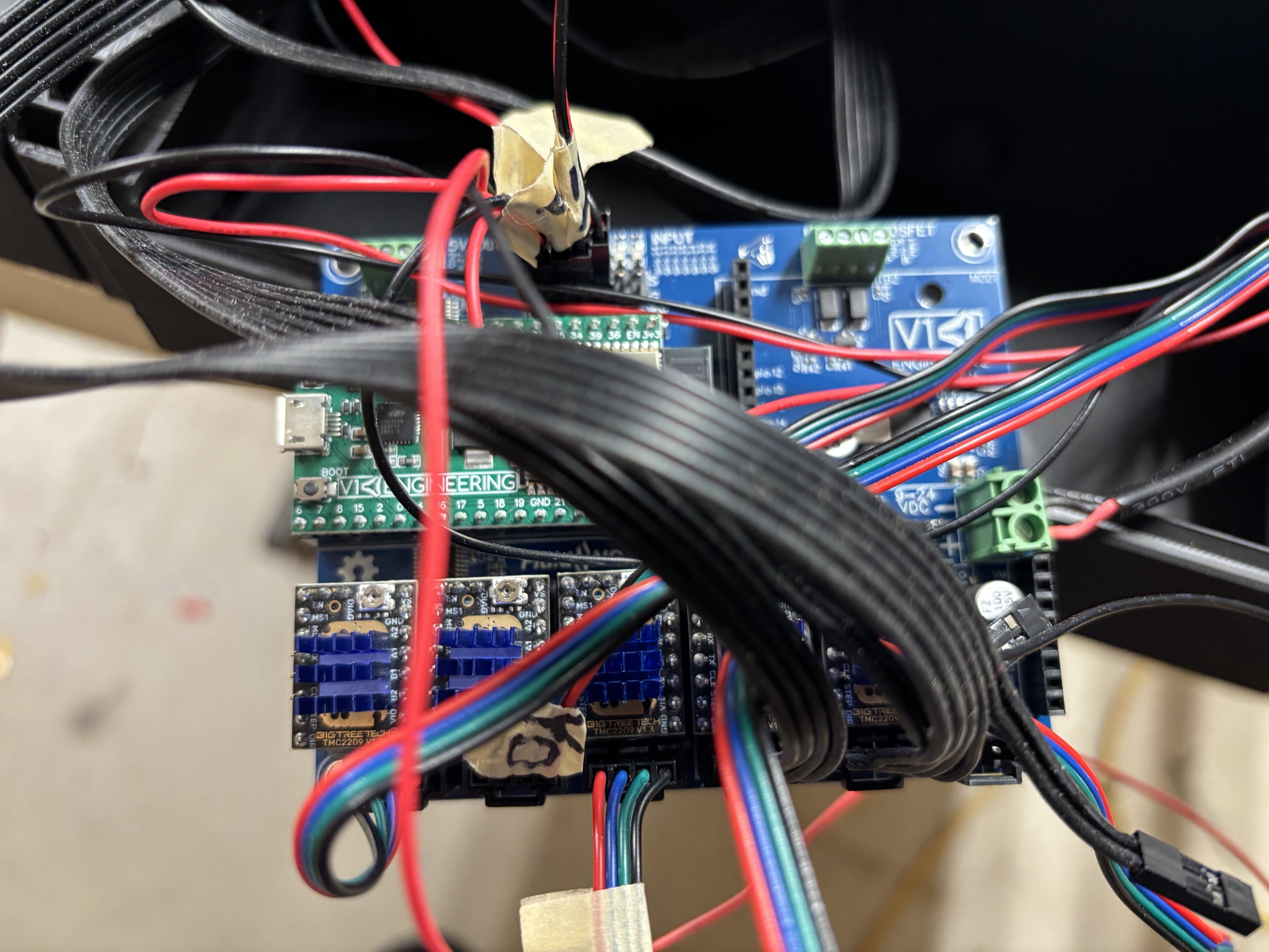
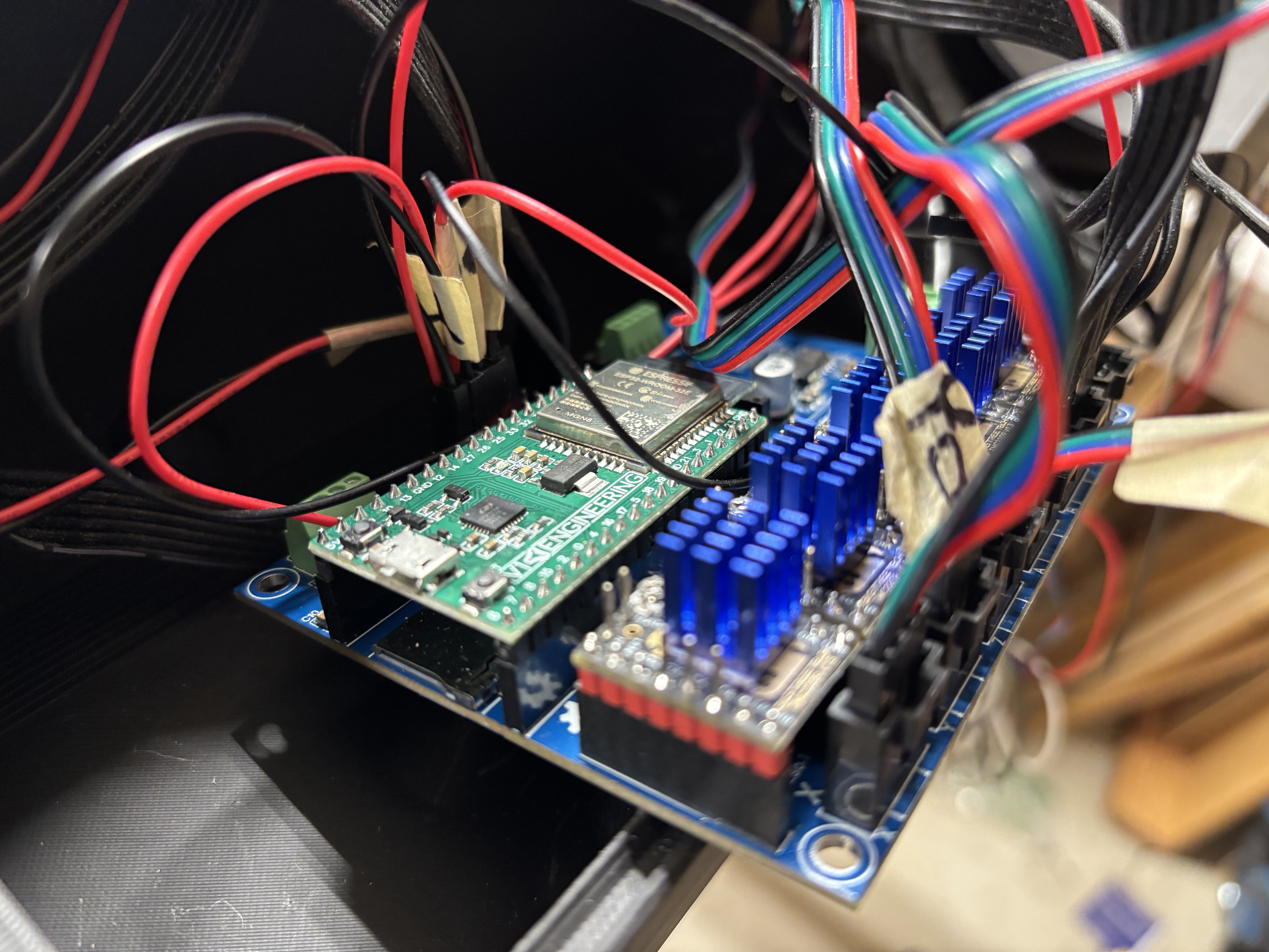
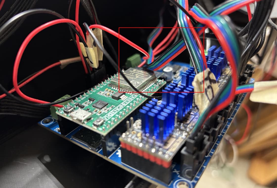
The general recommendation is not to cross the wires on top of the ESP32 so you don’t interfere with the antenna. The best way to do it is to pass things under the board and bring them up just enough to hook them over into the connector.
Also, if you’re running jobs from the SD card, you won’t need WiFi during the job itself. Although it will be super inconvenient if you just want to pause the job instead of hitting the E-stop. However, if you have reasonable WiFi signal at the machine, and you avoid wires over the top, I’d bet it drops less.
Last night after “reading” the destructions again, I see where it clearly says KEEP THE WIRES AWAY FROM THE ANTENNA
After rerouting the wires away from the top of the board, it stayed connected. I hope that is that on that.
Next will be to square the machine. Reading more than I normally would (given the wire thingy) it also seems fairly straight forward. Unfortunately, I will have to wait until after work to put it in motion. My thought process tells me to mechanically use the screws on the Y min on just the long diagonal once determined. We shall see.
Thanks to all for holding my hand during this build.
So after posting in the ‘advice’ section I believe through the help of many I was able to address the issues. I will detail all this in my next video on youtube.
Connecting the Jackpot to the local wifi was key to my issues going away (or so it appears). Might suggest this as part of the initial setup?
Once I power the machine, it automatically connects to my wifi. When I open my laptop which is always automatically connecting to same wifi, I click on the shortcut I made for the IP address of the board… and bingo… WebUI connects and we’re off to the races.
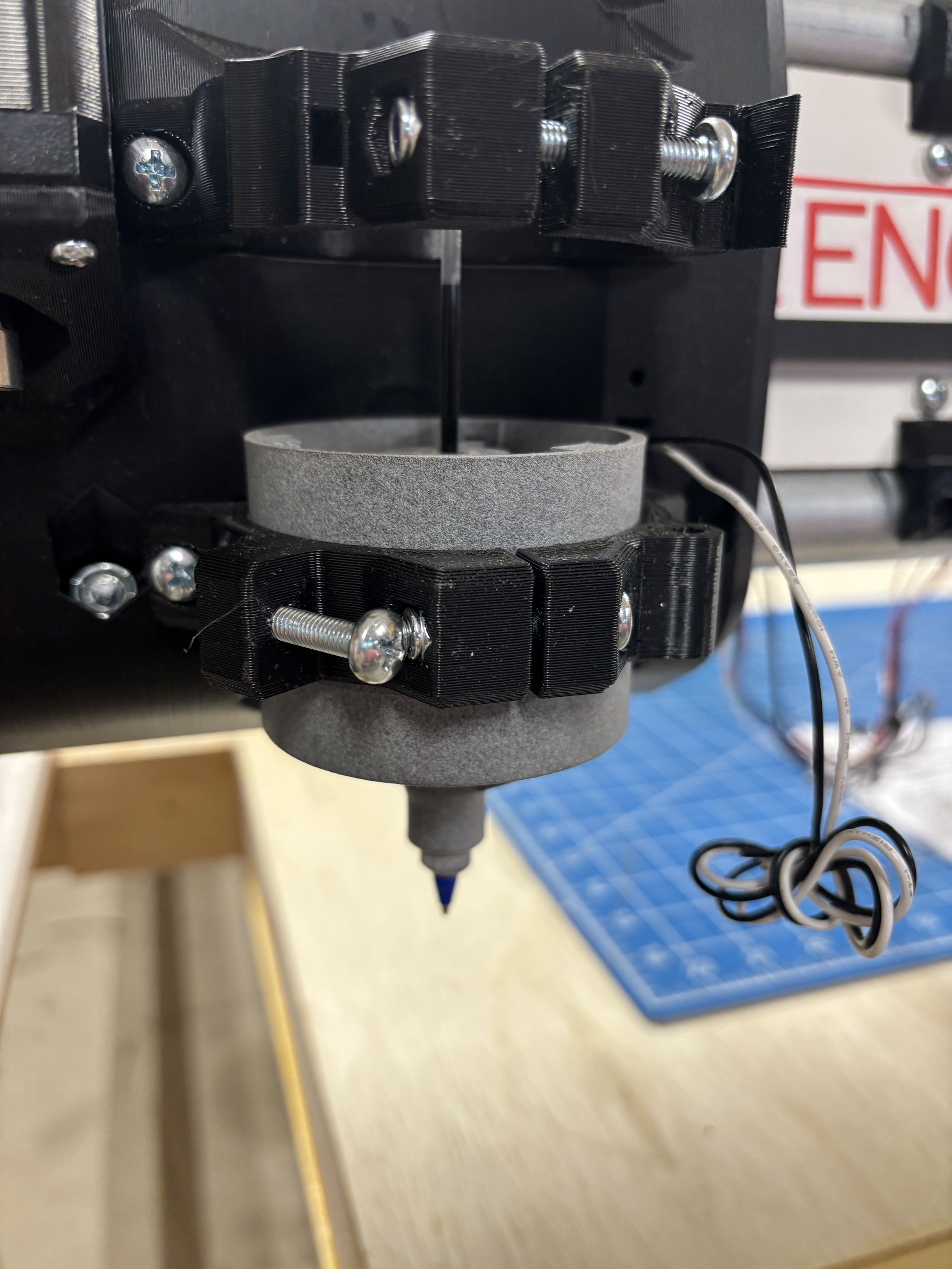
Next item on the list… connect the Z probe then actually draw the Crown.
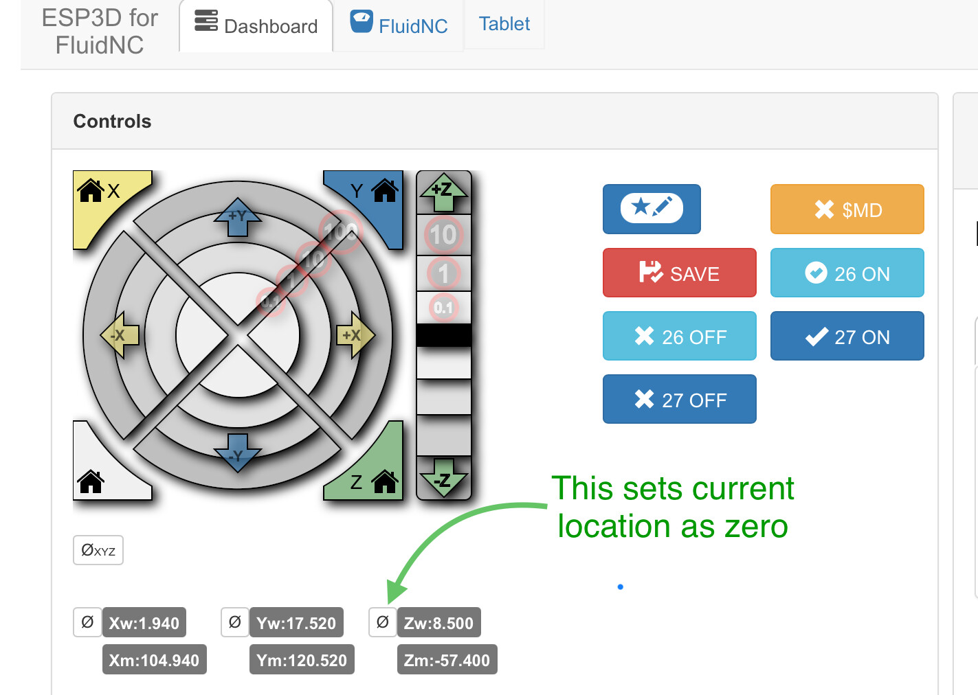
Good progress. You don’t need the probe - it makes setting the z0 easier but you can set z0 just as well by jogging down to juuuust touch the surface and setting z0 from the button on the FluidNC Interface.
Thanks for the reply, I’m gonna go ahead and put the probe in.
Actually on my Primo, I cheat the Z0 by setting it right where I want it and then powering up the machine and when it powers up, it thinks that zero for the Z then I’d XNY and it’s off to the cutting races
The probe that I had for the primo, I’ll use on the Lowrider with a quick disconnect so I can use it and then lose it