Exactly like that… folded over and taped. The rail side didn’t need extensions, however the non-rail side did (min side).
I will, however go back and check all connections just to be safe
Exactly like that… folded over and taped. The rail side didn’t need extensions, however the non-rail side did (min side).
I will, however go back and check all connections just to be safe
yup… all grub screws were tight to the test.
so I ran the file again w/o the router and it went through all 28 holes/pockets w/o any indication that it was not correct. I’ll cut some stuff tomorrow and see what happens. looking forward to my first real use. ![]() would be nice to pinpoint what caused the malfunction but I’d be happy if it just was a fluke and not happen again. fingers crossed.
would be nice to pinpoint what caused the malfunction but I’d be happy if it just was a fluke and not happen again. fingers crossed.
That is a tough one. Next time see if the failed stepper is hot or cold.
will do. I’ll cut some stuff tomorrow… need some clamps and such anyways… we’ll see what transpires. hopefully all good stuff ![]()
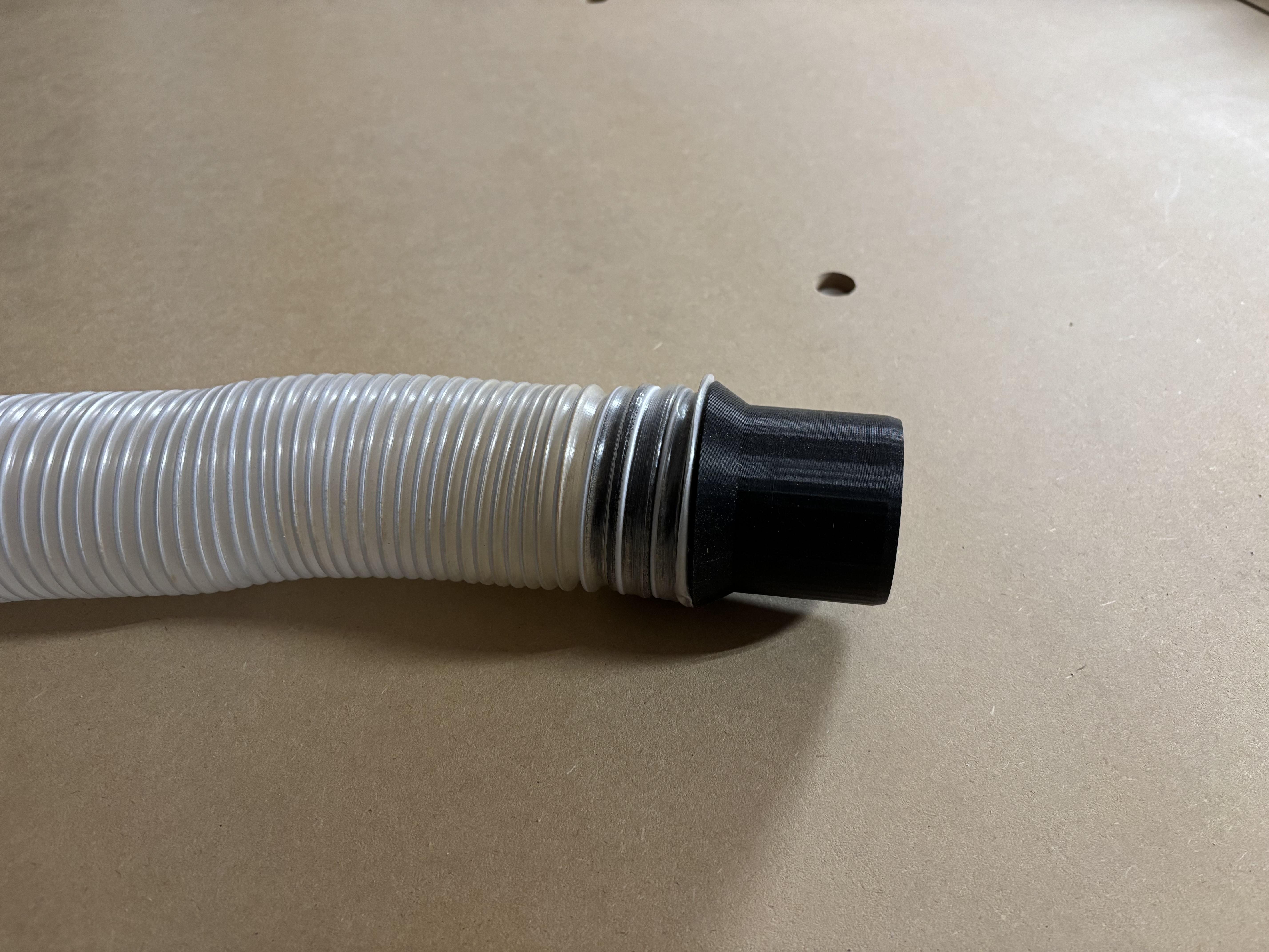
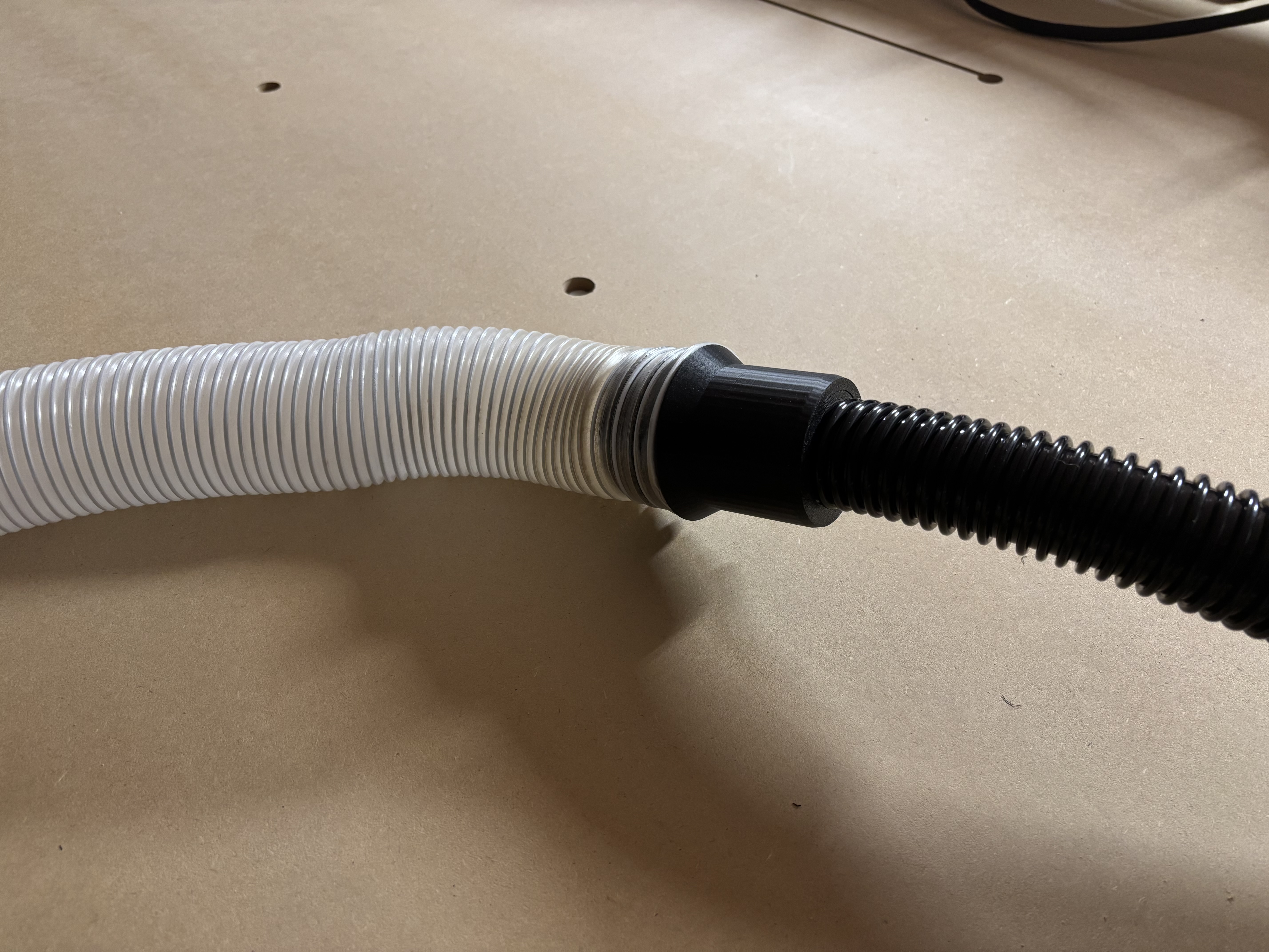
Well… I didn’t get to cutting anything today. However, I did manage to create a reverse-threaded coupling (using parts from other works) and printed out the following part. It allows me to attach the 2.5" dust collection hose to the Harbor Freight Hercules Dust Extractor which has a 1.625" hose (approx). it all fit snug and tight and plenty of extraction.
If anyone wants or needs, happy to share
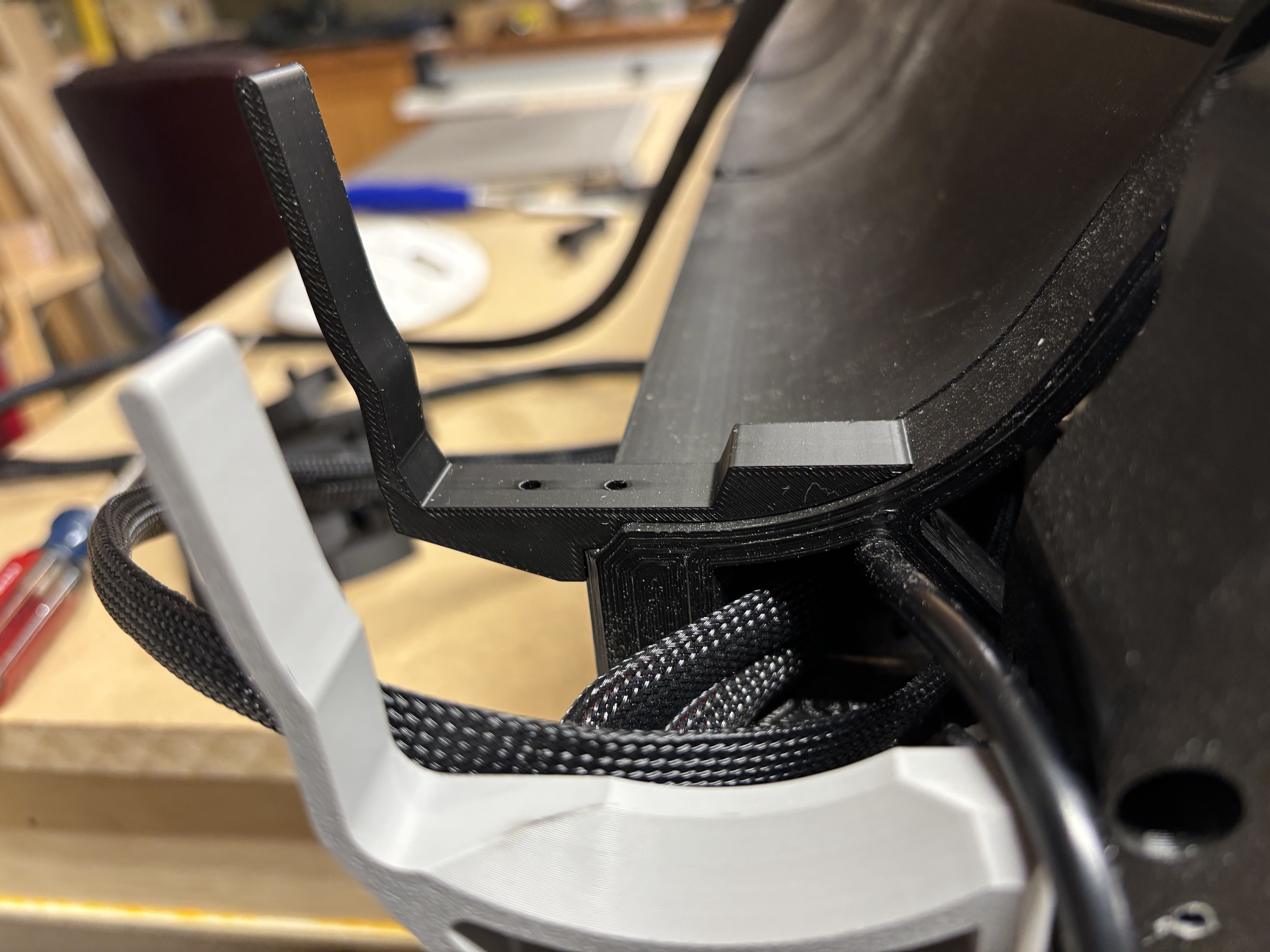
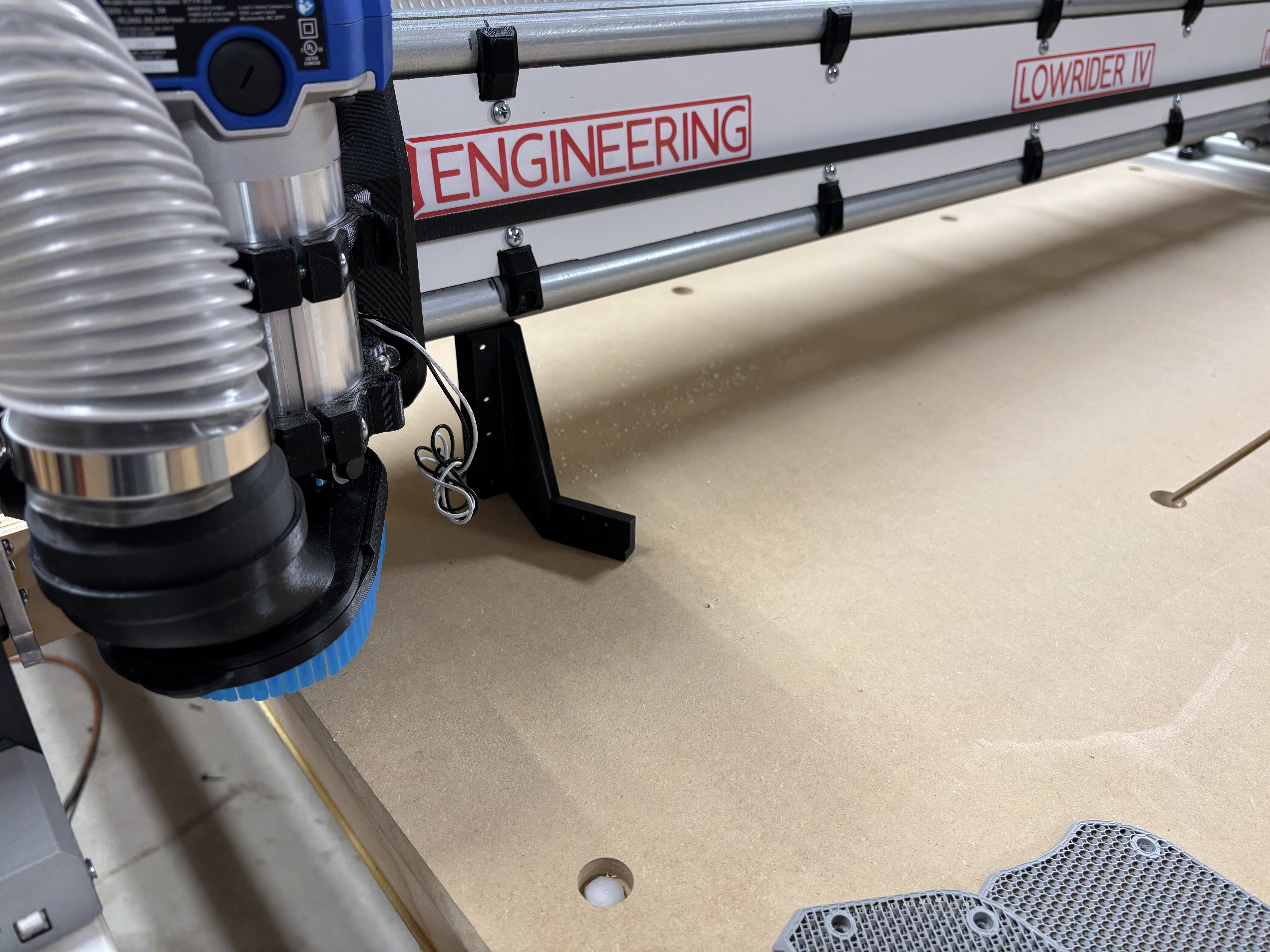
Working on a few odds and ends…. Recreated those little brackets that set into the gantry supports that included an area for a 15x30 drag chain.
I then installed drag chain for wires along gantry and recreated a mount on the core for that drag chain so that it sits higher than the dust collection hose that also shares the same space along the gantry. If this does not work, then I will likely make a boom arm for the dust hose from 3/4” electrical conduit.
That is looking great! Are you using a 2-1/2” dust hose?
Yes… the 2-1/2” hose referenced in docs (amazon)
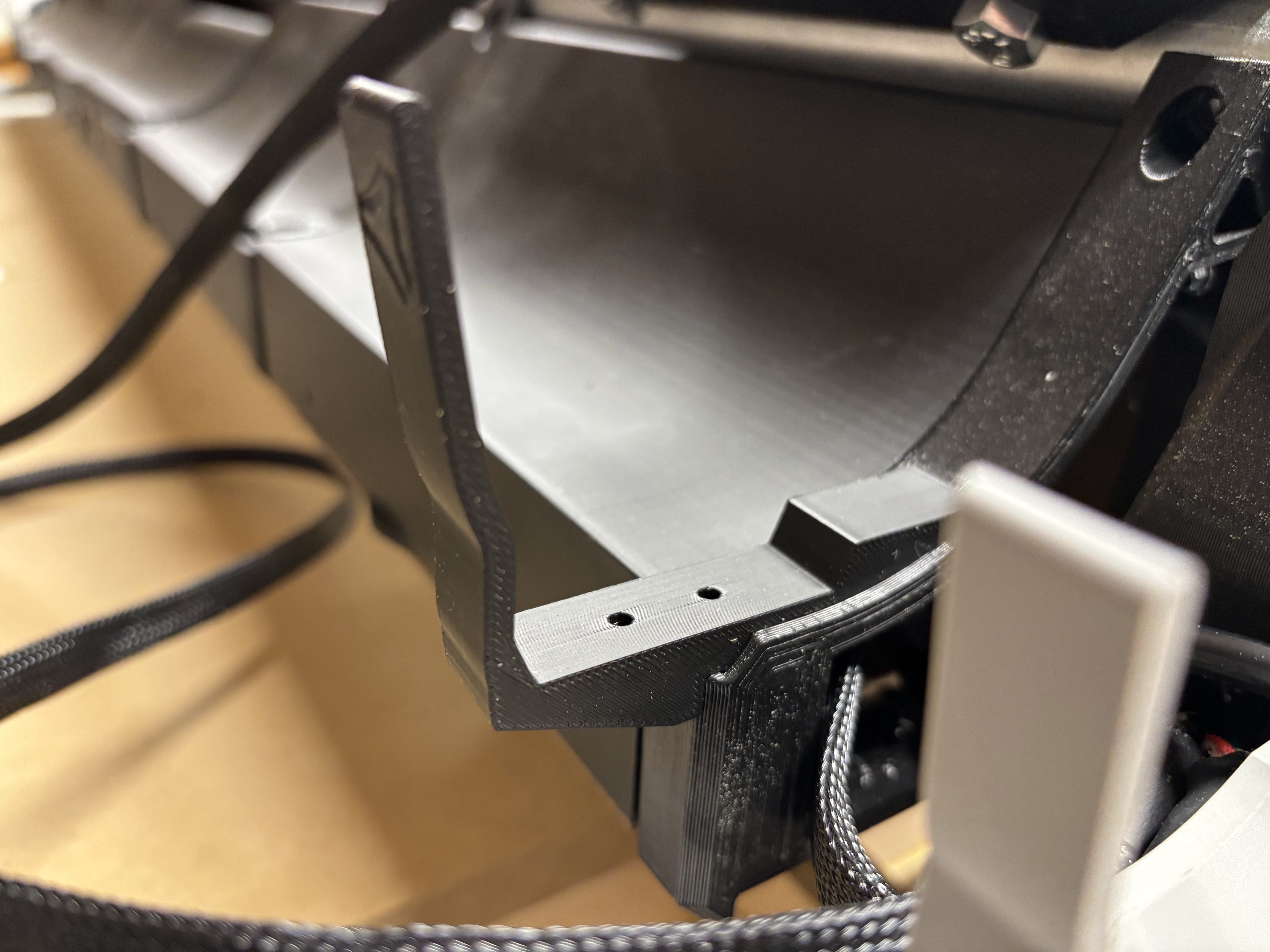
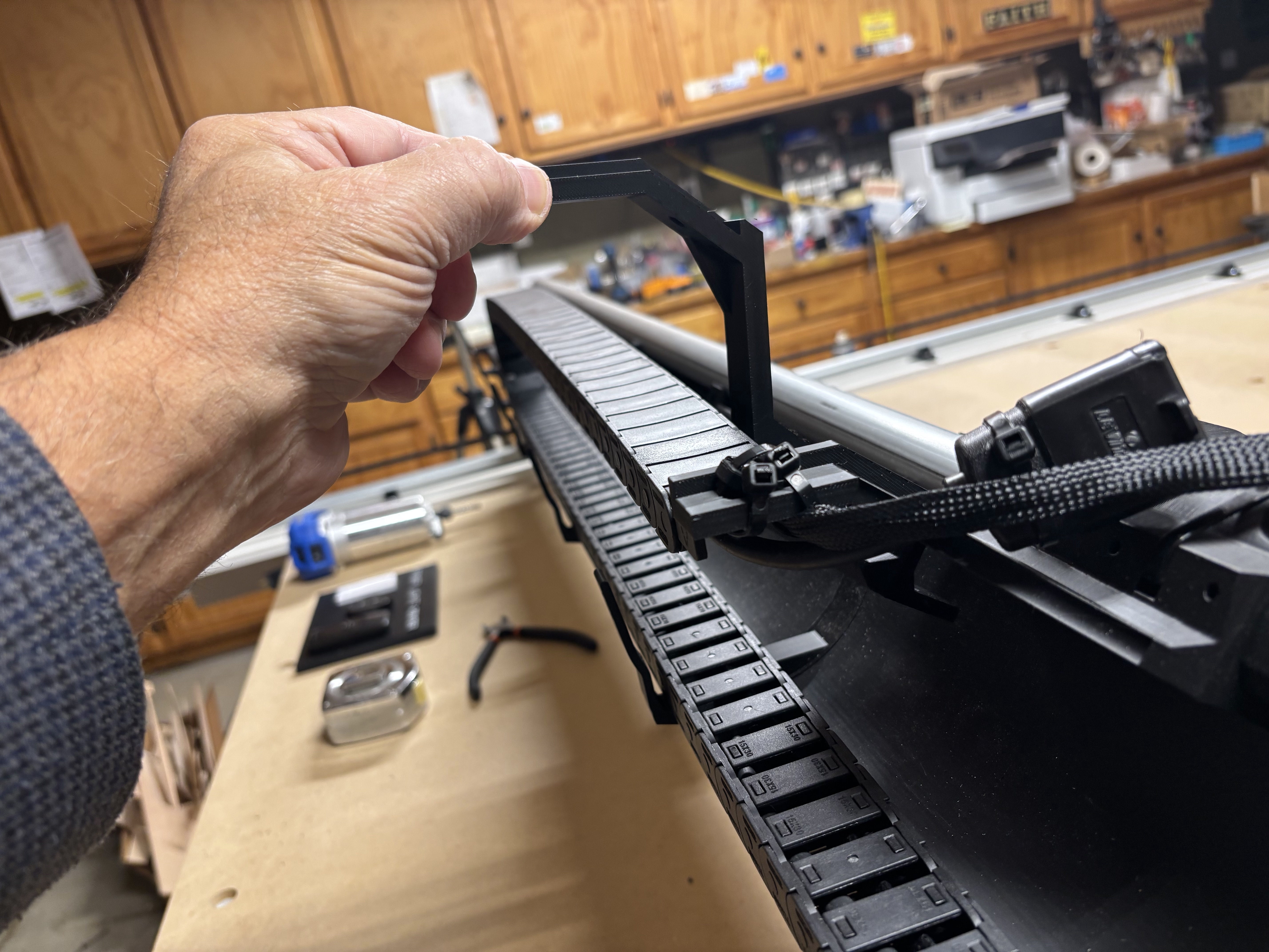
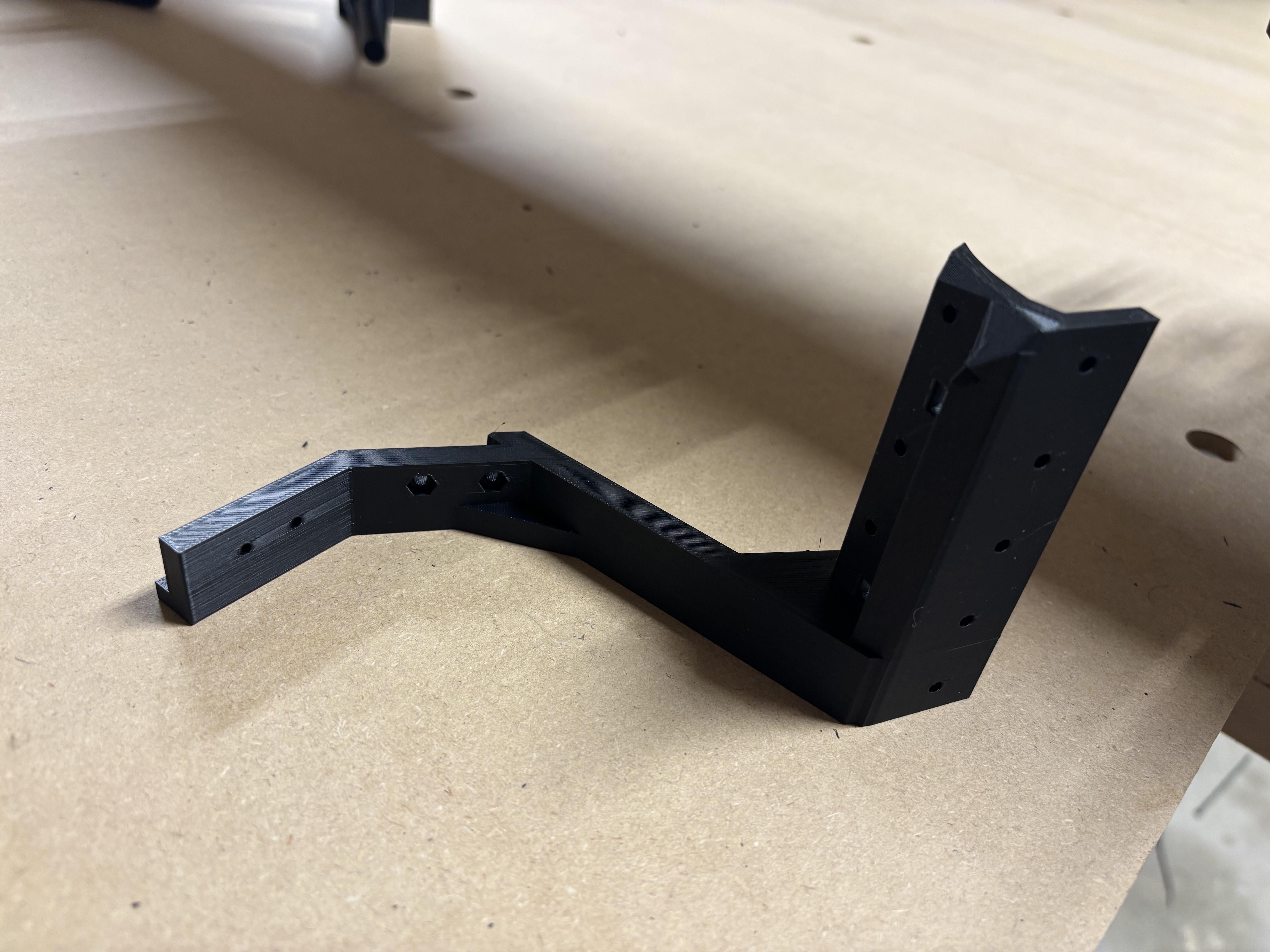
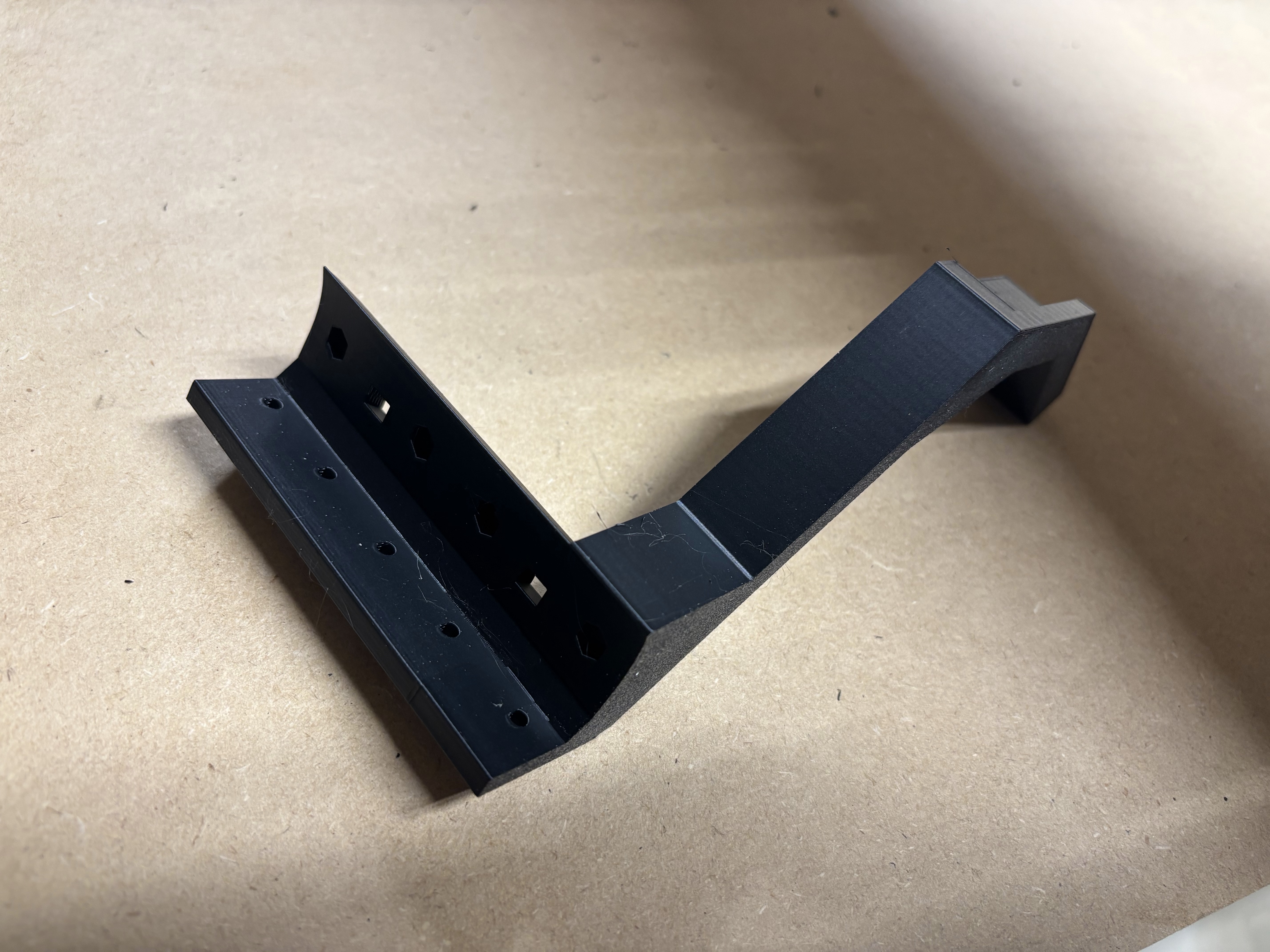
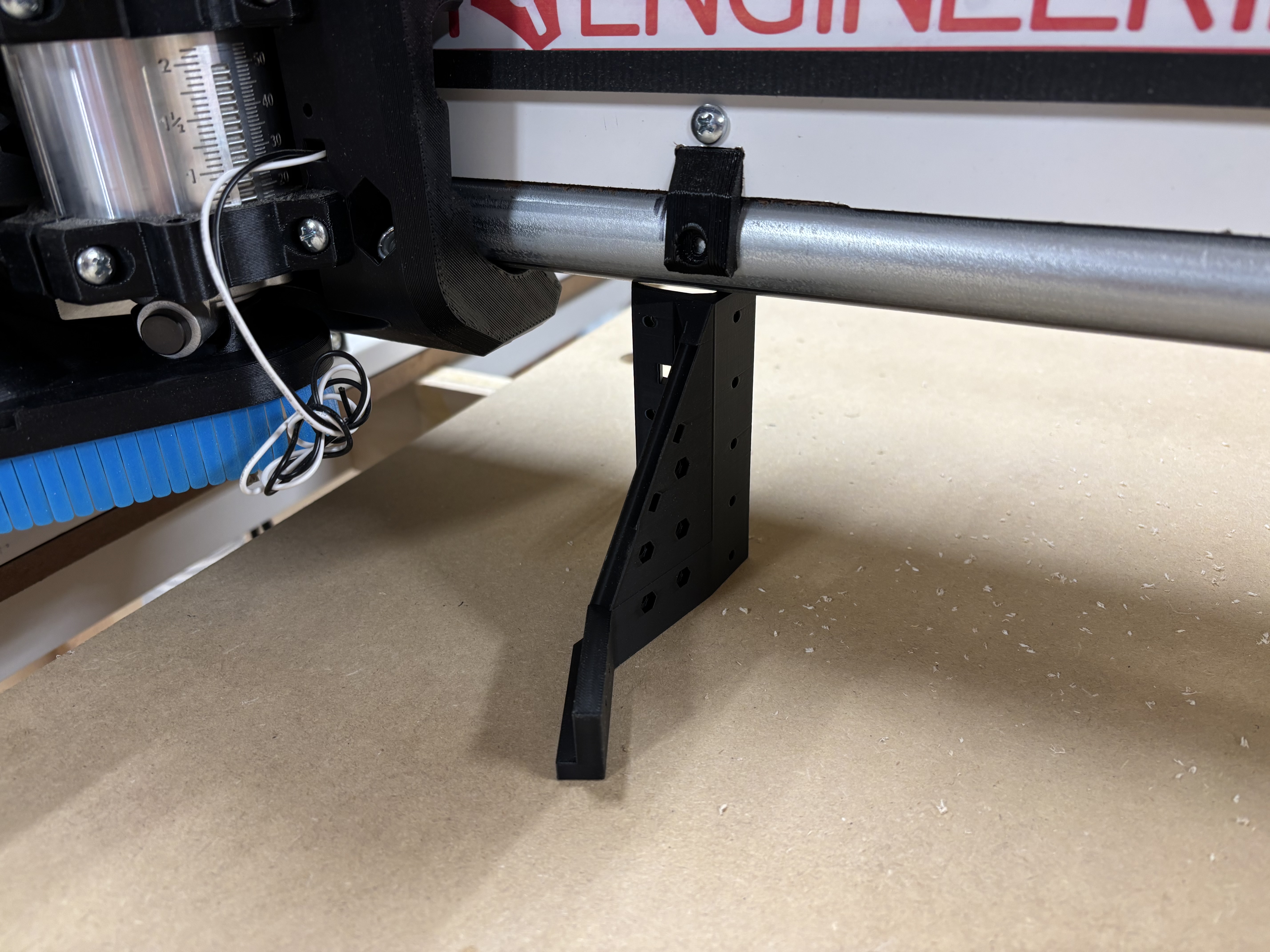
Found a good use for the drag chain bracket that I will not be using
Makes the perfect kickstand when I power down
Well today I attempted to “draw” the grid on the spoil board using 60* Vbit at .5mm deep and I learned that my machine will not go the entire 48" without hitting the rail side plate. I believe my strut plates that I cut on the MPCNC were off just enough to cause the space between X0 and X1 plates to be short. I tried 47.75" and it still hit. I was able to carve 47.5" along the X. I think I will rebuild the entire gantry (unless y’all talk me out of it) and this time make it to handle 49x97 MDF which I wish I had done in the beginning. ![]()
I did notice that when I home X, it pulls off and I assume that is ZERO… but it seems that when the job starts, it is a bit further off that pull off distance… this is where not knowing what one’s looking at comes into play LOL
How long are your gantry rails?
Whats the x motor pulloff you have in the firmware?
That pulloff should be 3-4mm. That accounts for the endstop travel so you can squeeze out every mm if you really want.
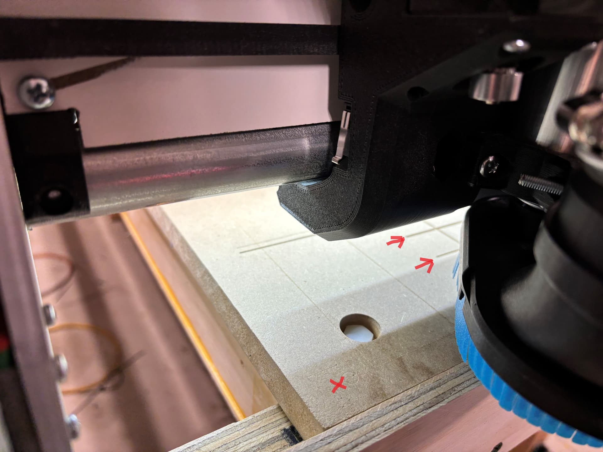
Ran a quick single line carve test 1" up from the bottom and 24" wide. the machine is starting the job well beyond that 4mm pull off point. not sure why it thinks x0y0 is so far off end stop in the X direction.
so this is the pic of the grid in Estlcam… I attempted to just carve one line along the X axis 1" from the Y min edge. I homed and it homed X and Y about where the red X is on the image.
and the work space is 1200 x 2438.40mm) and don’t have a problem with the Y as it is about 1/2" from either end of the 97" MDF.
then when I ran the job (which the 0,0 was the corner of the grid) it started the job where the arrow shows… way off the 0,0 actually 4-3/4" off what otherwise would be the edge of the min side.
and now I think that is why the core is hitting the max plate when trying to run 48" across as it is starting from a point other than 0,0 even though I home X,Y and Z before Z probe and job run.
@CesarH the distance between each of the aluminum plates is 54 3/4", the pulloff is whatever was default… verified it is set to 4mm
am I wrong thinking that the X0,Y0 is the origin and jobs should start from that point?
What is showing up un the x coordinate after you home the axis?
According to your estlcam origin it should start at x0
B I N G O
when I checked I noticed it was -100 when it homed… not sure how that happened, and I merely guessed at how to reset it. I had no idea that was even a button or what it would do but WTH, I clicked on it regardless. Then I saw it changed from -100 to 0, and once I did
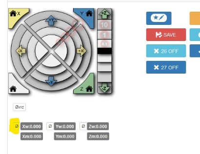
it carved the line in the correct location. LMAO. live and learn is the fun part of this for sure. but not knowing the right question to ask… as you did which prompted me to figure out what was out of whack.
thanks again… maybe I will puddy fill the screwy lines and redo this grid thing. ![]()
lol, it happened to me as well at the beginning, now enjoy making dust ( i mean, chips)
now to test a 48" line and see if it still slams against the max side plate fingers crossed!!!
Just ran the full 48" carve along the X… it fit fine.
now I will redo the entire grid after picking up the doggy from the vets…
will be making dusty chips tonight boys and girls. yah !!!
Excellent.