Oh something else I thought of, when I power it down, only one side drops down (X0). If I manually raise the low side by twisting the lead screw, I can get to a point where the other side will fall evenly with it. I’m not entirely sure what to do to get them to stay level and aligned.
Also I’m pretty sure when I homed Y after one of my tests, they were not even and Y-Max was last to hit its end stop. Y-Max end stop has the adjustment screw sticking out a decent amount, and Y-Min isn’t using a screw at all. After pulling off and re-homing, it was even and hit the switches at the same time again.
Sorry for the info dump, and thank you for the help!
This is normal. Assuming your core with the router is at X0 its that weight that pulls it down. Nothing to worry about. The machine is designed to allow for that. And when you start it back up and home it brings it right back level where it should be. If you power down and it doesn’t go down then its past time to lube your lead screws.
This most likely means that the Y max side had skipped steps at some point since you last homed. But once you homed it brought it back straight and that’s why they hit at the same time the second time you homed.
It was definitely too lose on my first circle test. I tightened it up like you’d described, the circles were a little bit better but not much.
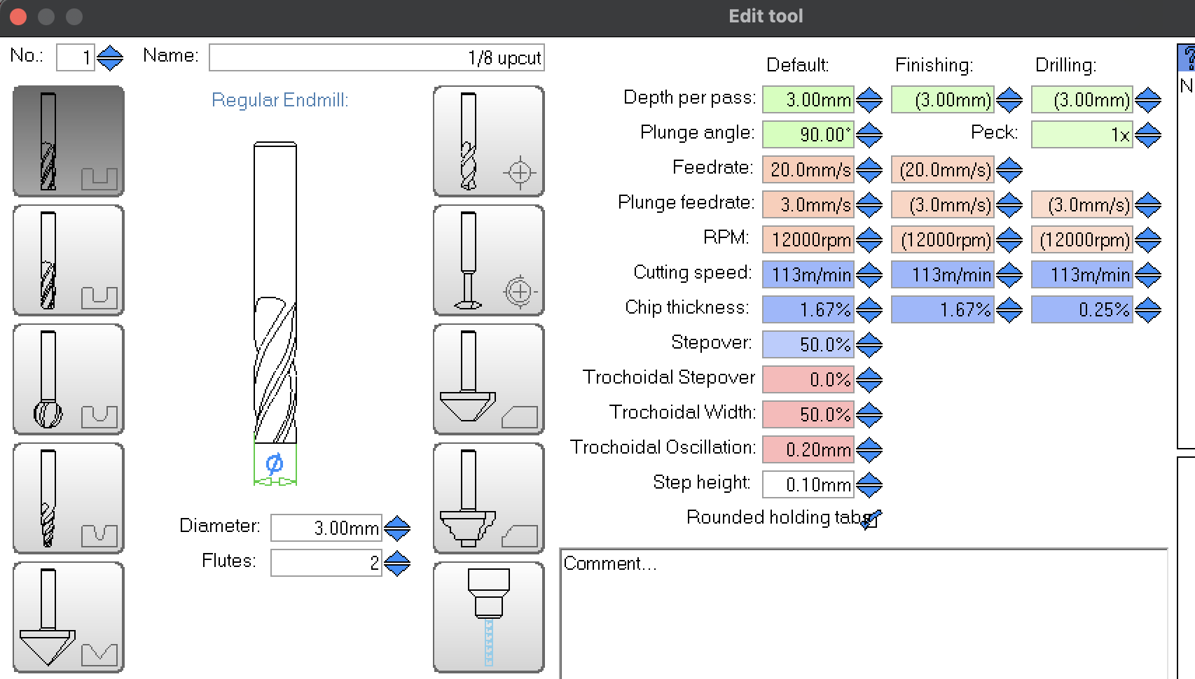
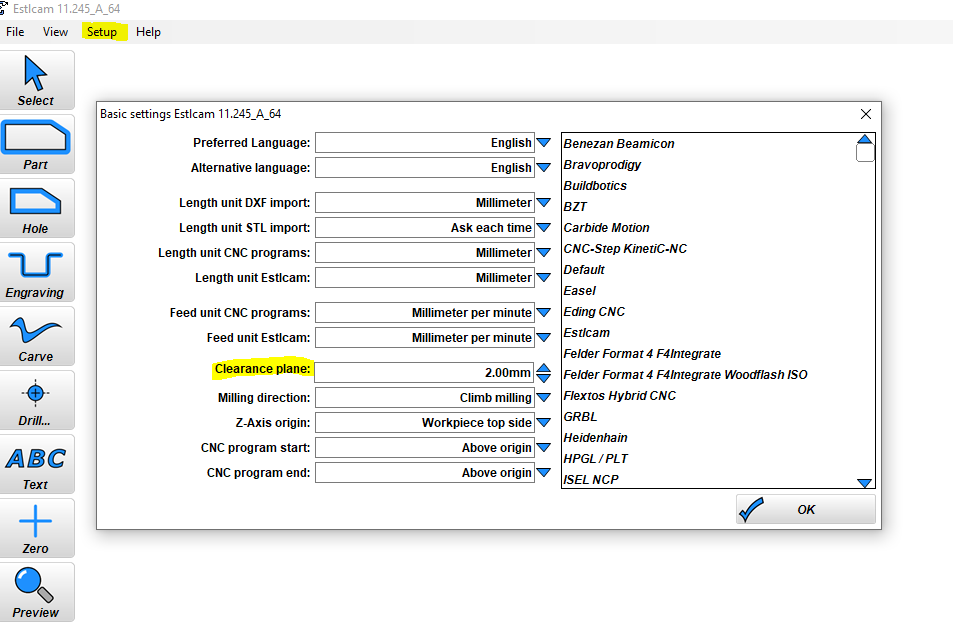
I have a feeling this is my problem, I’m using feed rates that were meant for testing my previous struts which should have been able to take it, but I doubt temp struts would perform well… I also was not cutting from X0, it was towards the outside of the temp strut, that could be the combo that’s killing me Screenshot below has federate at 20, but my “circle test” makes two circles at 10 mm/s, then 15 mm/s (as it was meant to see how my machine handled different speeds)
That makes sense, and makes me feel better knowing
Gotcha, and skipping steps sounds like it could be my problem when doing my hole test? What is the remedy for skipping steps/what causes it? I’m gonna guess that feed rates being too fast on temp struts, cutting away from X0 will do it? lol
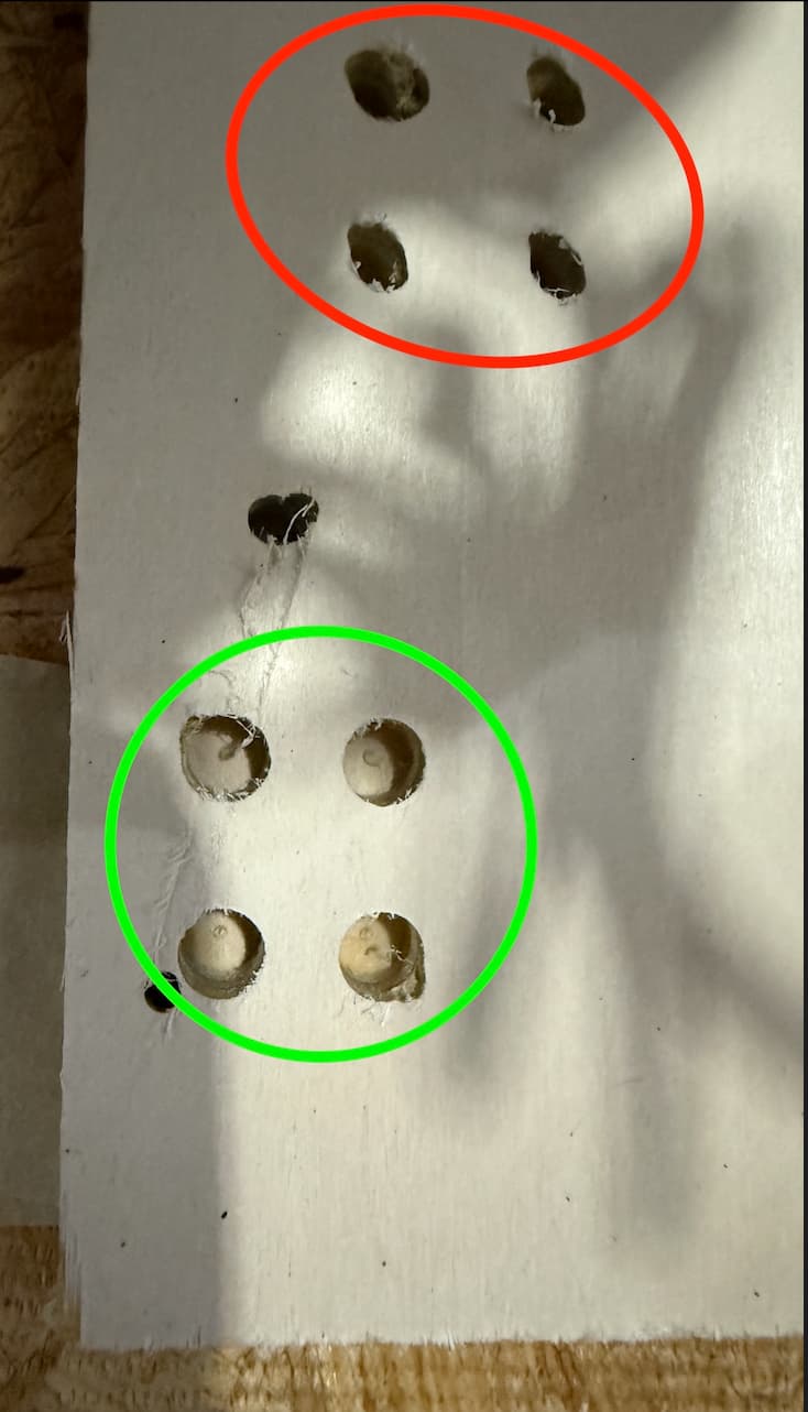
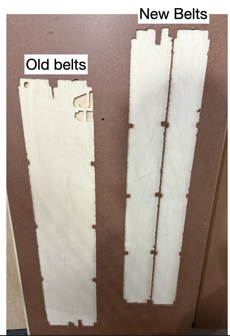
well, I think that might have been the solution! Two of them look about perfect, and the other two that have a little extra piece taken out, the little extra bit is only on the top layer of the ply. The ply is from the cheap offcuts pile at the local lumber yard, so I wouldn’t be surprised if it was just low quality wood unable to keep it together?
(first and worst attempt circled in red, that was with a loose core)
With the struts installed you “should” be able to run your original settings pretty well, but test cuts will prove that, and just more time running the machine. Those flimsy wooden struts make way more of a difference than you would ever think lol.
I spoke too soon boys (gender neutral)… somehow the braces are too tall to fit in the struts by a couple mm, the holes are not aligned with one another (though they are pretty circular), sharp right angles aren’t always cut right/they have a taper to them. Of course I didn’t realize this until I took the temp braces and core off…but I did some very much necessary wiring cleanup and got the temp struts back together. Got it all back together and realized my X motor got flipped around so I said to hell with it and took a late lunch break.
I’m wondering if I have stretched belts, either from accidentally over tightening, or from the machine crashing off the rails a time or two… I have a spare roll of belt, so I think I’ll replace them for good measure either way. It’s super easy if you (masking)tape the end of the new belt to the end of the old one, and just pull it through To start a new belt without one in there already, I’d tape a PETG filament piece to it and curve it hard, and use that as a lead-in device. Just a tip for those who didn’t know it yet. I’ll give this a shot in a bit and will report back.
A summary of all fixes and improvements (learnings) since removing the faulty braces:
Tightened the core properly, purple loctite on the grub screws, a few drops of silicone wd40 on the lead screw threads
Table is hella square, level, flat, and simplified
Fixing the X rail lengths allowed for heel-toe alignment. Alignment appears to still be easily lost (hence stretched belt suspicion)
Dialing the speeds down and keeping it tight to the braces allowed me to make almost perfect circles (stretched belts causing missing steps?)
Wiring game is now tight and tidy, per the docs
Replacing the belts now, will also make extra sure I’m using the correct strut brace svg
Removal of elevator plates remains an option if belts do not solve it
My overly logical mind is like “must. keep. going. there’s literally a finite number of things to fix, just keep checking them off the list” But it’s really the support from all of you keeping this thing going lol so again a sincere thank you to you all.
That is the best stuff to use on the lead screws. You should have gotten some with your kit, assuming you ordered from V1.
Do you have some pics of how the struts don’t fit? Something seems very off. Stretched belts is very unlikely. I have only ever done that once and it was super obvious in the section it happened. And that was outside forces that caused it, not the LR4. You will skip steps before you stretch a belt.
I am wondering if you used the wrong operation to cut your struts making them come out incorrect sized.
Ah, yeah I’m pretty sure I stretched a belt then The automated squaring test default move speeds are quite fast (IMO) and during one run, something happened and Y Max got pushed off it’s rail pretty far, and the belt had much more slack in it after that. I tightened the belt and it seemed like it was OK, the belt didn’t look distressed to me otherwise (not that I’d really know lol).
Anyways, I replaced all 3 belts and noted/fixed the following things:
Y Max pulleys were squeaky and hard to turn, lube fixed that issue
Y Min belt seemed OK, but replaced it anyways
X/Core was interesting… it had a hitch to it leaving shortly after leaving home, which turned out to be the tensioners being uneven/too tight. I slowly backed them off and slowly back in until whatever the bare minimum force was to keep it from rocking from a single finger on the bit. The grub screw on the motor’s spindle was also super loose, so I tightened it back in with purple loctite. X moves smoothly without the hitch now. While typing this I realize I didn’t check the Y motor grub screws so they could be a problem… adding that to tomorrow’s list.
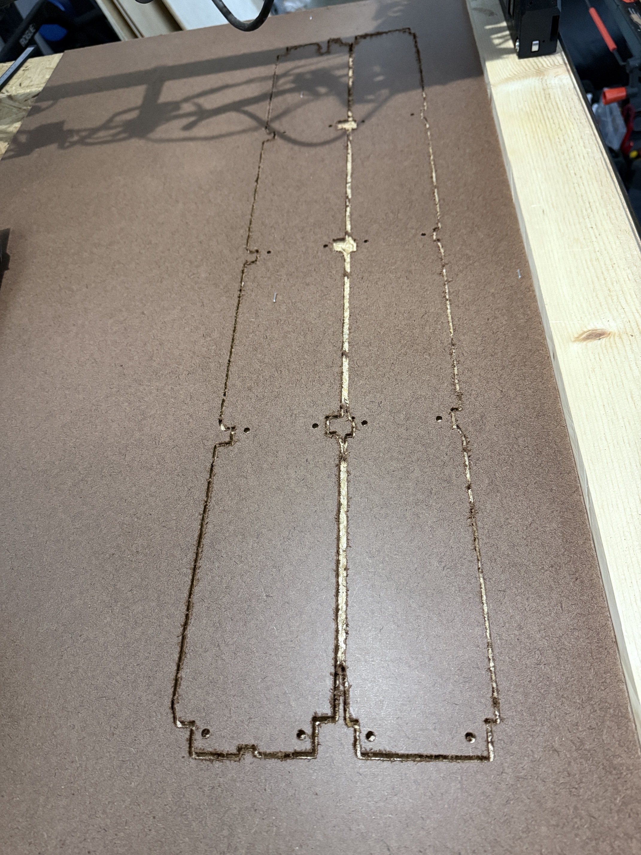
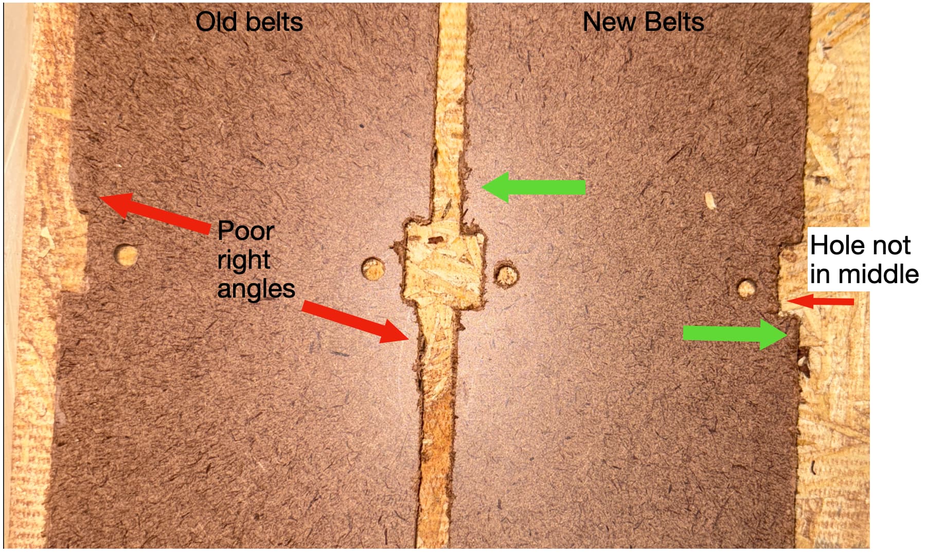
I re-cut the struts on the same material as before, same bit, same gcode, and the results are much improved but still some problems:
The lines are now straight
The braceheights are now consistent and correctly sized, ~2 mm smaller than before
Holes are perfect circle shapes IMO and consistent depths
The Problems
The holes are not aligned in their respective brace, and they seem to be differently positioned in each brace
Homing after the cuts showed Y Max taking longer to hit home, meaning steps were still skipped?
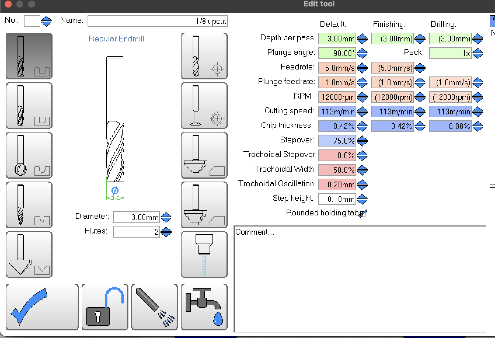
Bit: 3mm 2 flute upcut spetool, brand new and fully seated
Router: Makita router on dial setting #2
Major Settings: 5 mm/s Fx, 1 mm/s Fz, 3.75 mm cutting depth all in one pass (the hardboard is ~3.4 mm thick)
GCode made in Estlcam. Braces were CAMed via “Part” tool path button, holes were made with “Hole” tool path button
Pics:
Just comparing the braces that were closest to X0, since I realized that cutting the second brace to the right is likely too far out for the temp brace to handle
The edges seem to indicate that the stock may be lifting or moving during cutting. This can happen with thin MDF or hardboard.
I suggest to set up the cuts in EstlCAM to cut all of your screw holes first, followed by the parts. Then edit your g-code (w/ Notepad) to put a pause between the screw holes and the Parts. Once the screw holes are actually cut and the job is paused, then put a small wood screw into each hole. That will hold the MDF/hardboard to the spoilboard, with minimal movement during cutting.
Also I suggest you use a finishing pass (approx 10% of tool diameter), then VERY lightly sand the edges of struts after cutting.
You are skipping steps. That’s why its not lining up properly.
I agree with @Bartman to do your screw holes first, then you can put a screw through some of the holes and then do the part cut. That will help hold the material down better.
You might need to do 2 passes if you are still skipping steps. I wouldn’t think you would be with the settings you are running, but I never tried to cut struts with the temp braces so I am not sure how much weaker it is that way.
Thank you both for the tips! I’m about to test it with both suggestions: make the holes and pause, apply screws to the holes, and will do the cuts in two passes (2mm first pass and 1.75 mm second pass)
Y max grub screw was loose… I know one of my earlier messages I said that I verified the grub screws are fine, but I was only referring to the Z axis screws, I completely forgot that each belt motor also has a grub screw. Sorry about that… between the new belt and the tight grub screw though, we’re cooking with gas now!
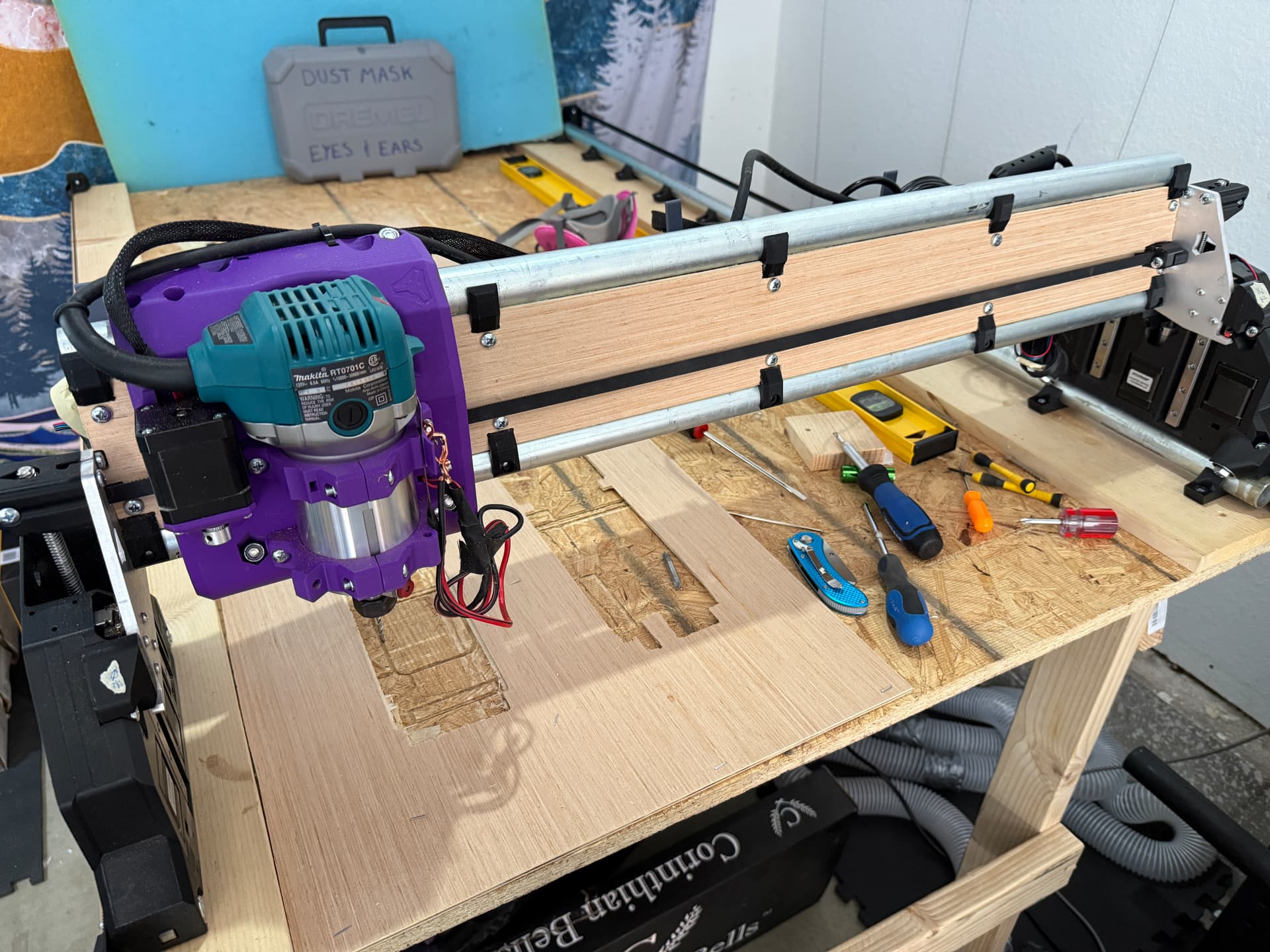
I first tried putting wood screws in the holes, but my wood screw was a little too big so I only used that first screw and then opted for staples between the other screw holes. It was looking great until my bit kissed the screw head and caused it to miss a couple steps, which was actually cathartic because the next right angle it cut was off like it used to be, so it totally verified the idea that I was skipping Y steps before.
That was my last piece of hardboard so I switched to plywood of similar thickness
I did not use the wood screws and stuck with the staples. Cut the front/top brace in two passes, everything lined up and looked good!
I installed that brace and made sure the heel toe is equal. Now I’m making the job for the second brace in estlCAM and will go and cut it shortly
I did not do a finishing pass on the first brace (I cleaned up the edges with a utility knife) but I’ll try and do the finishing pass on this one
Edit: will do a “final” tidying of the wires in a bit.. gonna reward myself with the Hercules HEPA dust extractor from Harbor Freight, so I still gotta run that hose and will ofc get the wiring squared away at that time
This is excellent advice and I appreciate it, in this case the head of the screw was too large in X/Y so it poked out a bit into the cutting path of the outline of the brace. My bad for not wording it better
Been bouncing between FreeCAD and F360, didn’t really like either and am now giving AutoCAD 2024 (Mac) a shot. So far it might be perfect for me, it seems to be a lovely mix of GUI and Terminal, meaning that to use tools, you can click on an icon like always, but if you wanna be a smooth operator, you simply type the first couple letters of the tool name and hit enter…and if you get good at that, you type name of tool, then type the parameters like how far you wanna move something in X and Y, and hit enter. So you can do most things without taking your hands off the keyboard (and there’s no holding shit/cmd hot keys, you just type!) which makes you mega efficient. This video may be 2 hours long, but the first 15 minutes got me further than weeks learning FreeCAD/360, he only uses keyboard shortcuts for tools so you only learn to be efficient, it’s great lol. https://youtu.be/jSZOcSagios?si=LmFAGRRmztAftl2I
Put more simply: AutoCAD is the first CAD with a measuring tool I could actually figure out how to use, and I’m pretty good with software
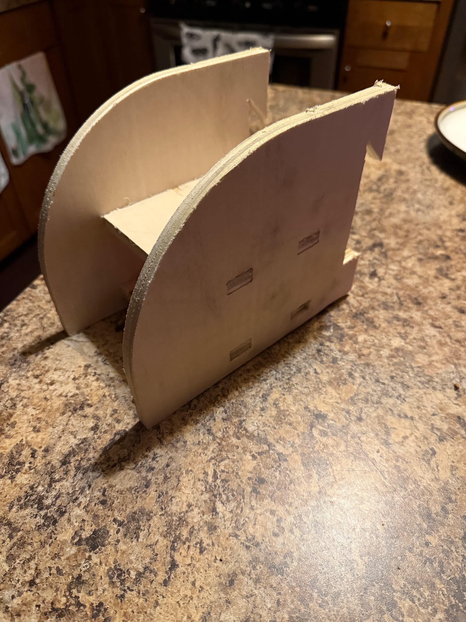
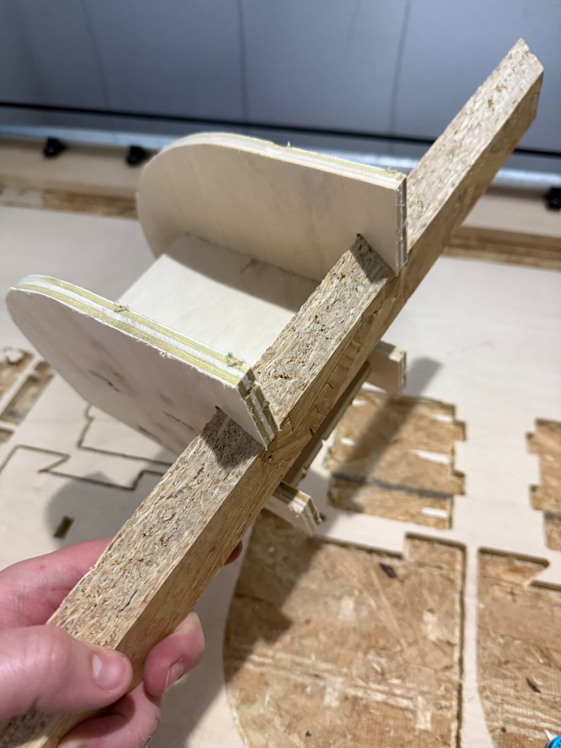
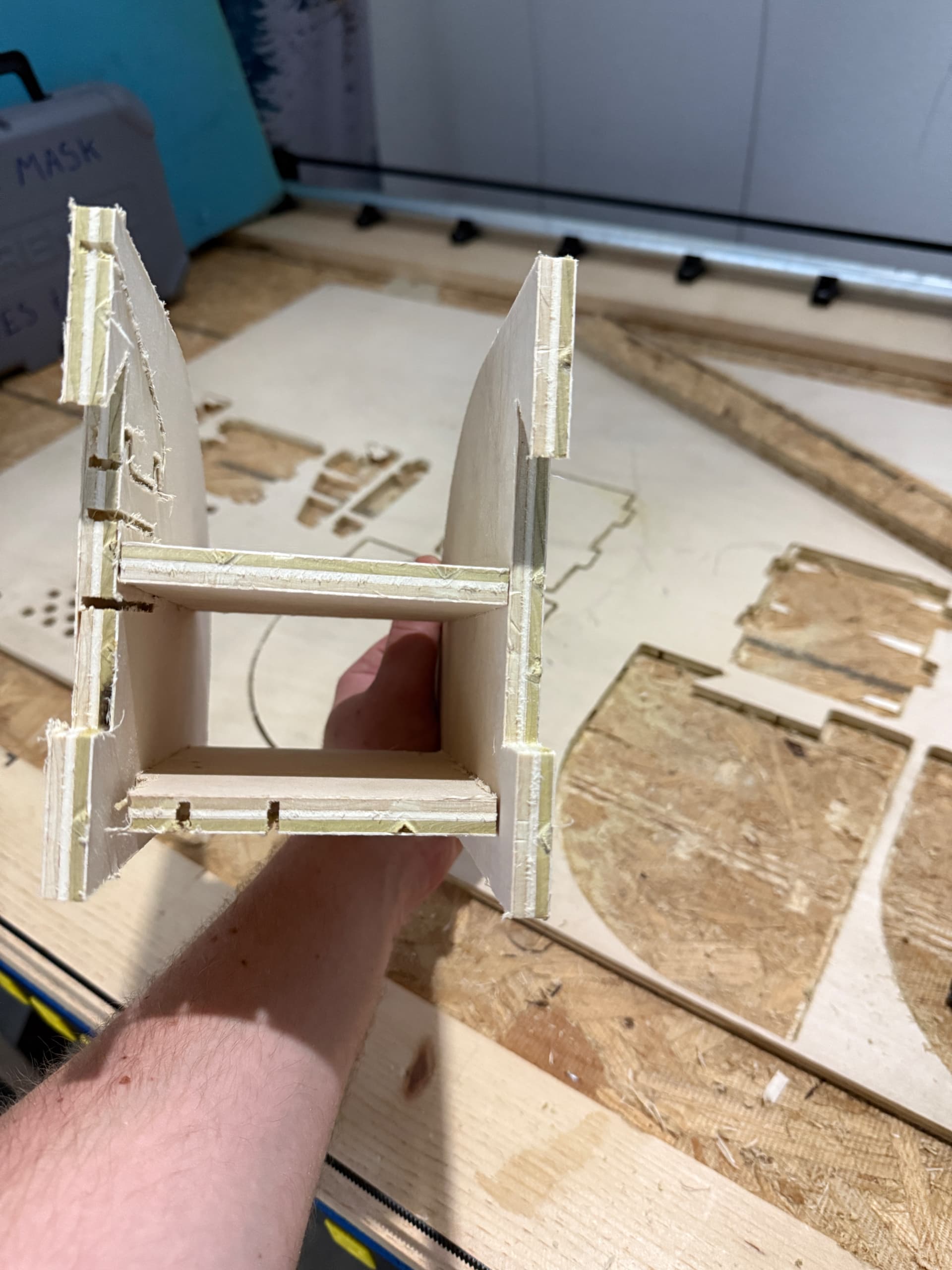
Anyways to cap off a successful weekend (thanks again yall!) I tried my hand at making a French cleat “unit” for my computer monitor to clamp onto… first ever thing I edited heavily in CAD (it’s based on @Tokoloshe ‘s cordless drill holder) and then made on the CNC! It ended up a little jank because it’s scrap wood that already had cuts in it, and the first attempt my Y Max grub screw came loose again so I loctited it back in and cut again. I went to press the pieces together and was like “uhh why it no fit? CNC must be broken again” and then the tab and the opening are the exact same size!! So I hit it with a mallet and it went together like a dream (minus the cracked and broken parts from the scrap wood lolll)
It’s damn beautiful and I’m so excited to bring it to work tomorrow and show the boys lol