LR4 build by a complete newbie

TL;DR: Totally new to 3D printing, CAD, and CNC. Strong background in geology and computer science (remote sensing) and I’m an avid DIYer (car maintenance etc). Decided to jump into the LR4. Every day is a new challenge. It’s a pain in the ass learning 3 new hobbies at once, but in the best way :wink:

Long winded intro post because everyone IRL is sick of me talking about “my CNC machine”:

Hey all, back in May/June I became obsessed with the idea of a CNC machine. A buddy started going to woodworking classes and they had a CNC machine, so he was telling me all about it and I was hooked right away! He made me a telecaster guitar body and ever since I’ve been obsessed with the idea of making every dream guitar out there, like to be able to have an exact replica of a Gibson SG for like $100 in material… and to be able to say you made it yourself?? Priceless.

To me this Lowrider CNC is a way out. A way out of financial anxiety; why buy what you can make? A way out of the mundane/a creative outlet; It’s like DIY on the computer, my two favorite things! I find myself spending hours every night reading about CNC, messing with the build, or learning CAD… it’s certainly a high challenge, high reward type of hobby, but that’s exactly what this ADHD brain craves!!

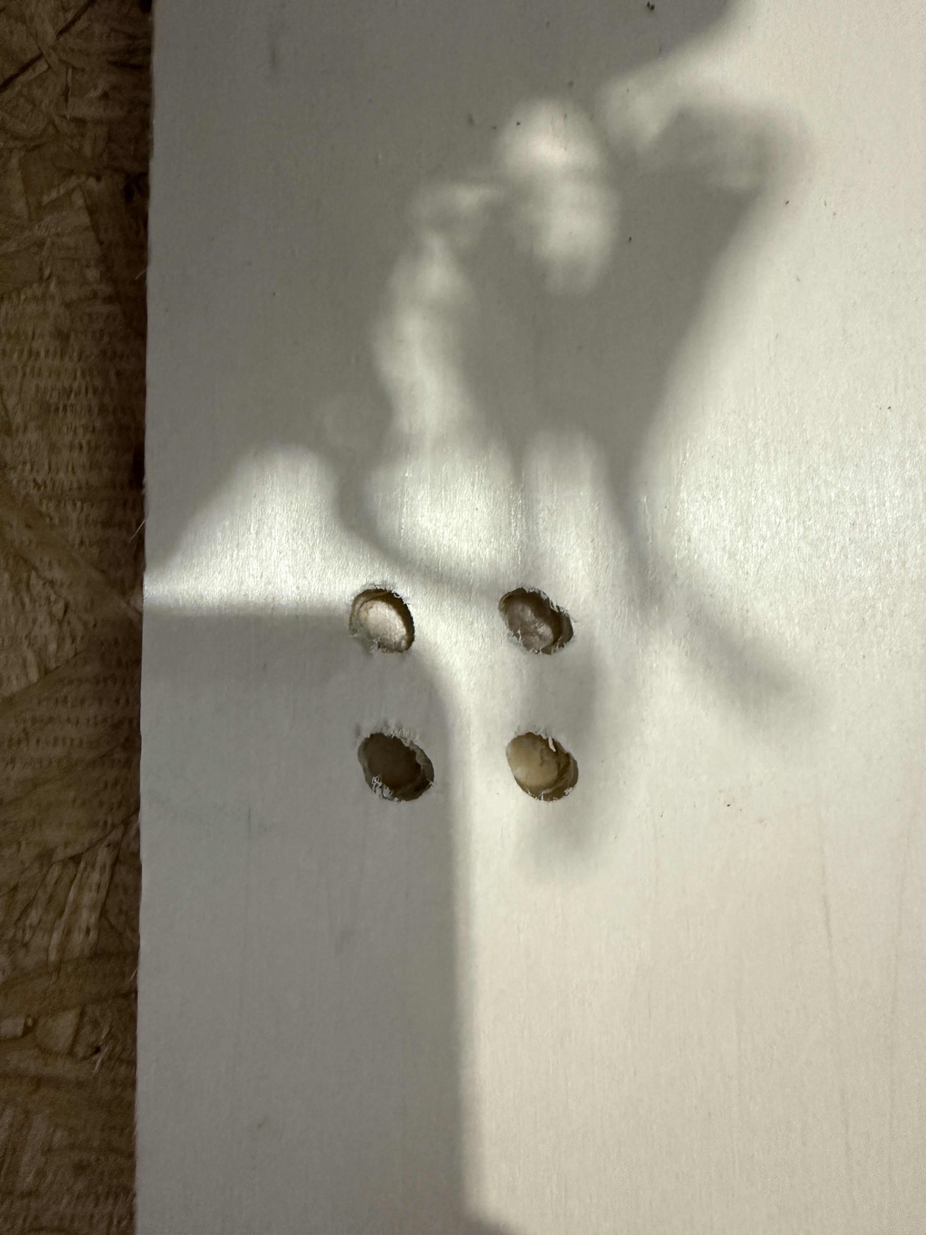
So I justified buying my first 3D printer because it was gonna build me a CNC machine, and my wife is cool as hell for going with it lol. I mistakenly printed all of my LR4 with supports, and then foolishly spent soooooo much time trying to rip out all the supports. Fast forward a couple months to now, and I’m still setting this thing up because I goofed up bad… I thought I was all done building and could finally cut stuff! But the circles I cut looked like ovals. Spent a whole day tweaking things and it kept getting better, but still ovals. Realized it was my strut plates, which were also cut poorly in retrospect.

What-had-happened-was I 2D printed (lol) the instructions so I could better focus on them and take notes in the margins (ADHD represent), but my dumbass didn’t check if I had printed the entire thing, so I didn’t do anyyy of the calibration or squaring :sob:.

I printed new temp struts and got ‘er situated, but then I tried to home Z before the squaring test, and it basically blew right past the limit switches so I cut the power… turns out the Z1 switch is broken (thank god for those little lights on the jackpot). I traced the wire and redid my janky wire work but no dice. No big deal I thought, I already have a 10 pack of micro switches because I broke one during assembly lol… but no friggin clue where they are!! So I’m channeling my daily CNC energy into my build/intro thread :slight_smile:

Many thanks to everyone for all the help and thoughtful words not just in my first thread asking for help, but in all of these threads- this community is special and I’m thankful to be a part of it! Now on to the cool stuff…

7 Likes

So prior to realizing my build wasn’t square, I knew the machine was way too loud to be used casually in our attached garage. And that’s a bummer because it’s my robot, and I want to use it casually lol.

I knew I wanted some kind of soundproof enclosure, but I also knew adding mass to the top of the table would be bad news, so I struggled for a while to think of something that’d work. But eventually it hit me…

I had some old curtains in my “diy scraps” box, and a giant baffle of rockwool insulation, so I essentially turned the curtains into pillows stuffed with 3” thick rockwool :smiley: To drape them over my table without adding too much wobble inducing mass, I attached QTY4 2x4s along Y0 sticking up vertically (plenty tall to clear the machine). Y1 is along the wall, where I mounted QTY4 steel eyes into the studs, parallel to the 2x4s. I then connected steel cable (that stuff is so cheap wtf) from the 2x4 to the respective eye-in-stud, so it’s kinda like a suspension bridge?

Anyways, I draped the heavy ass “sound proof curtain” over top of it, and holy crap does it work!! I mean it’s far from perfect, but for a “hey let’s see if this works”? It definitely works!

…it just looks stupid :rofl:

I don’t have dB numbers yet, haven’t bothered since it has obvious improvements to be made as the back and Y1 wall are totally exposed and free to echo. I need to stuff rockwool under the table too, luckily I still have more lol. Will share an update when I have it better sorted out

6 Likes

That’s the great thing about this forum - we never get sick of you talking about your CNC machine

This was totally me a couple of years ago!

Also me a couple of years ago.

Looking forward to seeing your build progress!

4 Likes

I’ve said on these forums before that every adult gets to choose their own risk tolerance, but because you’re a self-identified newbie to CNC and 3D printing I feel the need to say be really careful running the CNC when you can’t see what’s going on under the blanket. Cavemen started fires with friction around tinder/sawdust, and the basic physics behind that approach are still valid. A tool spinning 20-30k rpms will ignite in a literal second if things get stuck and start rubbing the wrong way. There are more than just a couple of examples online of folks who have burned down their machines, shops, or whole houses through a very short period of inattention.

This gets extra dangerous when you’re new to both hobbies because 3D printing is so much more protected from inadvertant flame-ups, and it is safer (not saying 100% safe, but safer) to let a print job run unattended. It’s easy to see the machines as largely similar, but the fire risk is not at all comparable.

4 Likes

Oh absolutely agree with all of that! And I’m glad you bring it up because I (and I’m sure many others) assumed you could just let it work like you would a 3DP.

A crucial detail missing in my sound proofing post is that I can easily lift up any part of the curtain and take a peek at what it’s doing, so it’s not flying blind :). I either stare at it in awe the entire time, or watch it get started and then stand right next to it and periodically (every few seconds) check in by peeking thru the curtains. I also keep a fire extinguisher on hand at all times just in case.

But yes safety is always #1 and again I appreciate you talking about it!

3 Likes

Welcome to the V1 community forums. You’ll fit in well here.

As others have said, we won’t get tired of talking about your machine!

I’m looking forward to seeing your build thread and knowing more aobut how you use your machine.

Again, welcome!

And then…

I’m putting my safety hat on. Please never leave your machine in operation outside of your direct line of sight for even a few seconds. These things are kilowatt class fire starters, limb removers, and murder robots. If you let them run amok, they could kill you or burn your house down.

Now that I’ve been dramatic for emphasis… back to it.

4 Likes

Lots of progress today and a question for the gurus:

  1. I replaced my Z1 limit switch successfully
  2. I tried the automated squaring test using G-Code Test Pattern Generator
    - This took a few attempts to get running properly, but I got it to do its thing and make the 4 corner markings
  3. After measuring my diagonals, it appears they are off by 15 mm, which sounds like a huge number to me?

My question(s): The build guide says to adjust Y axis pull-off… I found the config settings in FluidNC (Jackpot) webUI, but I’m not sure what exactly I should do to apply the adjustment. Like if my difference is 15 mm, which Y motor do I apply 15 mm of pull-off to? Using Y0 just for examples sake, it currently has 4 mm pull off like all other limit switches, so would I make it 19 mm? Something tells me 15 mm is a lot and that I might have other issues, but I also don’t know shit lol.

1 Like

15mm is a LOT. More than you should be correcting with settings (IMO)

I would guess that your endstops (the part that the Y limit switches touch against) aren’t attached to the table squarely. I think that you should be able to use the small screws on the endstops to get within a few mm, without using the offset, but you may need to reposition the endstops first. (I have an LR3, not an LR4, so maybe someone else can chime in here if I’m out to lunch…)

Maybe post some pictures of your table, with the endstops clearly shown.

2 Likes

Ooo yeah good call on the endstops, I’ll investigate those right now as best as I can… Earlier when I thought my setup was good to go, I moved the table to the back corner of my garage and it’ll be a royal PITA to pull it back out… I mean I’ll do it if I have to, but not tonight lol.

1 Like

I would suggest that you do all of your setup and calibration first (including both a test crown, and a test cut) before you jam everything into a hard to reach corner. Things like leveling the gantry, tramming, surfacing (if needed), etc. are much easier to do in an accessible area. It may save you several times of having to dig it back out to make changes.

3 Likes

Yeah for sure. I went out and basically determined that my table is just poorly made, not shocking since it was my first ever table lol. I swear it was all even and level when I built it but it’s certainly not now, so I’m sure I was just trippin when I first put it together. It’s all good, I’ve been wanting to blow it up and start fresh anyways…

I think I want to do a floor build and have the floor machine make its own table, and just do it the right way. I’d love to do a full sheet but it’d have to collapse or be wall mounted some how so I could still work on the cars when needed, and that sounds like a lot of added complexity to me…I’ve seen some awesome solutions from people here, but I don’t think I need to make this even harder than it is lol.

Is there a preferred “CNC your own” table design? I’ve seen a few threads of people talking about the designs, but I don’t recall any being referred to as like “the standard bootstrap table that everyone uses” kind of thing. I’ll keep reading though

1 Like

Anything flat (including the garage floor) is good enough.

Ryan has a basic parametric table.

Doug Joseph has a torsion box table that is pretty nice, although probably more than you really need.

2 Likes

Thanks for the link (and the help ofc), reading that thread makes me think my table is OK and I just need to look at the end stop placement/alignment, like you first suggested. Will report back hopefully tomorrow

2 Likes

Garage floors are often designed to slope toward the door and possibly toward the center. If your table started out flat and now it isn’t, I’d suggest adding some way to re-level things when you move them, or mark the floor so you’re sure of getting things back in the same place once they’ve been moved.

Levelling feet can be as simple as a t-nut and carriage bolt in the bottom of the table leg, or you can get a number of bolt-on solutions. Simple wedges for shims can work well too, especially if you’re only moving between a couple of preferred locations.

I built a twist into a stitch-and-glue sailboat hull because I didn’t take the complex slope into account when setting thing up. By the time I’d glassed the seams it was too late to true things back up.

1 Like

I pulled my table out from the corner and did some things, took some measurements, would love a diagnosis:

  • I removed my sound dampening curtain and the 2x4’s holding it up, turning it into a more basic table
  • Surprisingly, my end stop width only differed by ~0.75 mm (0.75 mm wider in the back/YMax)
  • My table is level now, I raised the front like 1.5"… the garage floor tilt is no joke!
  • I made sure my grub screws are solid with purple loctite, my X rails aren’t touching the XY plates, my Z screws are lubed
  • Now on to what my problems most definitely are:
  • My heel toe is off by 3 mm, wider up front. I have messed with this so many times and I can get them even, but it seems they get pulled out of whack. I checked all the screws and they’re tight but not too tight I don’t think (temp struts)
  • When I run the automated squareness test, it cuts ~2.5 mm deeper at X Max than X Min, for both Y Max and Y Min
  • I saw a bunch of stuff about drop tables and was always like “why wouldn’t you want some extra cutting depth?” so I made mine with whatever I had on hand, which was like a 1"x12" pine board that I ripped into strips to elevate my rails. Tomorrow I’m gonna try removing them and just building flat on the table…my table top is OSB though so I’ll probably need to grab some MDF.

Post two pictures, one of each side of your X axis (Gantry). We want to see where the EMT sits in the end brace. Each tube should be slightly inset from the brace. If any of the tubing is sticking out beyond the brace, this is an issue to work.

If you made elevator plates, then you can always take them off for testing.
The MDF I made my elevator plates out of is very consitent thickness.

Get a large straightedge (a metal level is usually a good candidate), and sweep it around your table. We want to find out if you have high or low spots and/or a crown in the center.

1 Like

Thank you! I couldn’t get a good pic of the X rails but I can confirm they are part of the problem, I could only slide a piece of paper between one side and not the other on the bottom. On the top rail I’m like RIGHT on the edge of the braces, so I’ll definitely file them down! Doing the paper test was crucial cuz it looks like it’s not touching, but an unseen part was and the paper found it for me…

Taking the elevator plates off will have to wait for tomorrow/weekend, will update once complete.

I passed a 4’ alu level (brand new nice and straight) and it was pretty much flat throughout. There was a small peak detected in the middle, but only perceptible at /just/ the right spot and angle of the level, and even then it was .5 mm or less

Trimmed 2-3 mm off my X tubes this morning before work (this thing is a real addiction haha), now they sure as shit don’t rub! I ran out of time to do anything more than trim and roughly put them back in place, will focus on getting the heel-toe situated this evening. Pics of the rough tube placement below, they aren’t perfectly aligned left to right yet, but you can definitely see that they won’t be rubbing… hopefully I didn’t trim off too much of it tho lol not end of world if I did, I have extra conduit I can cut up :slight_smile: anyways:

At a bit of a loss guys, I was able to square it up (heel toe identical) and I did the automated squaring test and it looked like it worked as intended. My diagonal measurements came out within 1 mm, and I was so encouraged! Then I had it cut four small circles, and they came out as ovals again man… and I measured heel toe after that and it was again back to being 3 mm wider at the toe. I figured maybe I had the temp struts loose, many screws were loose so I evened it back up and tightened the screws. I also swapped the bit for a fresh spetool 1/8” upcut (which is what was set in estlcam). I ran the circle test again, and again they were ovals, and again the heel toe was out 3mm to the front.

Only thing I haven’t tried is removing the elevator plates, but I rrrrreally don’t want to and they seem pretty flat and smooth to me… but I will if I have to. Could really use some guidance as always, it’s so close to being good man I can feel it :slight_smile:

1 Like

Is your core “snug” to the rails? If it can rock at all that can cause some issues. If it is loose tighten it VERY SLOWLY. no more than 1/16 turn at a time just until the bearings cant come off the EMT any longer.

What are you settings in estlcam for that cut? On temp struts you will want to go real light and slow with your cut. Also make sure you are cutting as close to X min as you can since that is where the temp strut is

2 Likes