Oh that is not sketchy, you even have pocket screws!!!
Oops sorry, philipp, lmao
Oh that is not sketchy, you even have pocket screws!!!
Oops sorry, philipp, lmao
Ok quick update. Well we got a bit of winter show up which definitely slowed me down the last few days, but i did learn a bit about estlcam and got my LR4 to draw me a picture.
I then went on a several hour read and youtube video watch to learn how to use estlcam a bit better to do cutting and started the struts. The biggest thing i learned, my garage floor is definitely NOT as flat as i thought and I should have had the clearance set higher as my first attempt dragged the endmill when drilling holes on the second strut. I’m also wondering if things have shifted a bit since i originally put it down on the garage floor when it was +15C outside to now -10C outside…and oh so much snow). But we learn from our mistakes right?! ![]() .
.
so then i recut just the front strut, setting up the cam file again. Ooof, this did not go well! Not sure what happened here but none of the hold downs came through in the print, the chip kept stopping the print and giving me warnings of low memory and with all that… it didn’t cut deep enough. So I will try again tomorrow (after more research!).
But she looks pretty!!
Also still need to learn how to set the depth of material too, i stupidly didn’t buy the touch plate originally but have it on order now too. But a good little project to start and learn with!
Also!!! All was not lost! When i came in from the shop, a little surprise showed up for me:
Looks like it might have been an issue with estlcam possibly as a new version was released that printed absolutely perfect last night. Couldnt be happier! So pumped I decided to attempt this. Will be on vacation for the next week so these will sit as is until I’m back. Then I begin the table build to get this off the floor.
I was thinking the garage floor was a pretty clever way to boot strap the process. Though the flatness problem is understandable. I think if a guy was in need of an emergency 4x8 on a budget the concept is sound. I think my version Would be 2 sheets of OSB, rails of something flat and straight. for the cut area maybe 1/2" (might have to go thicker depending on how flat the floor is) blue foam taped down to the OSB. with a facing bit you should be able to get it flat enough.
I don’t see it lasting long but it should be enough for the table build
What a week of vacation with too much food and whiskey followed by an absolute week of down right sickness.
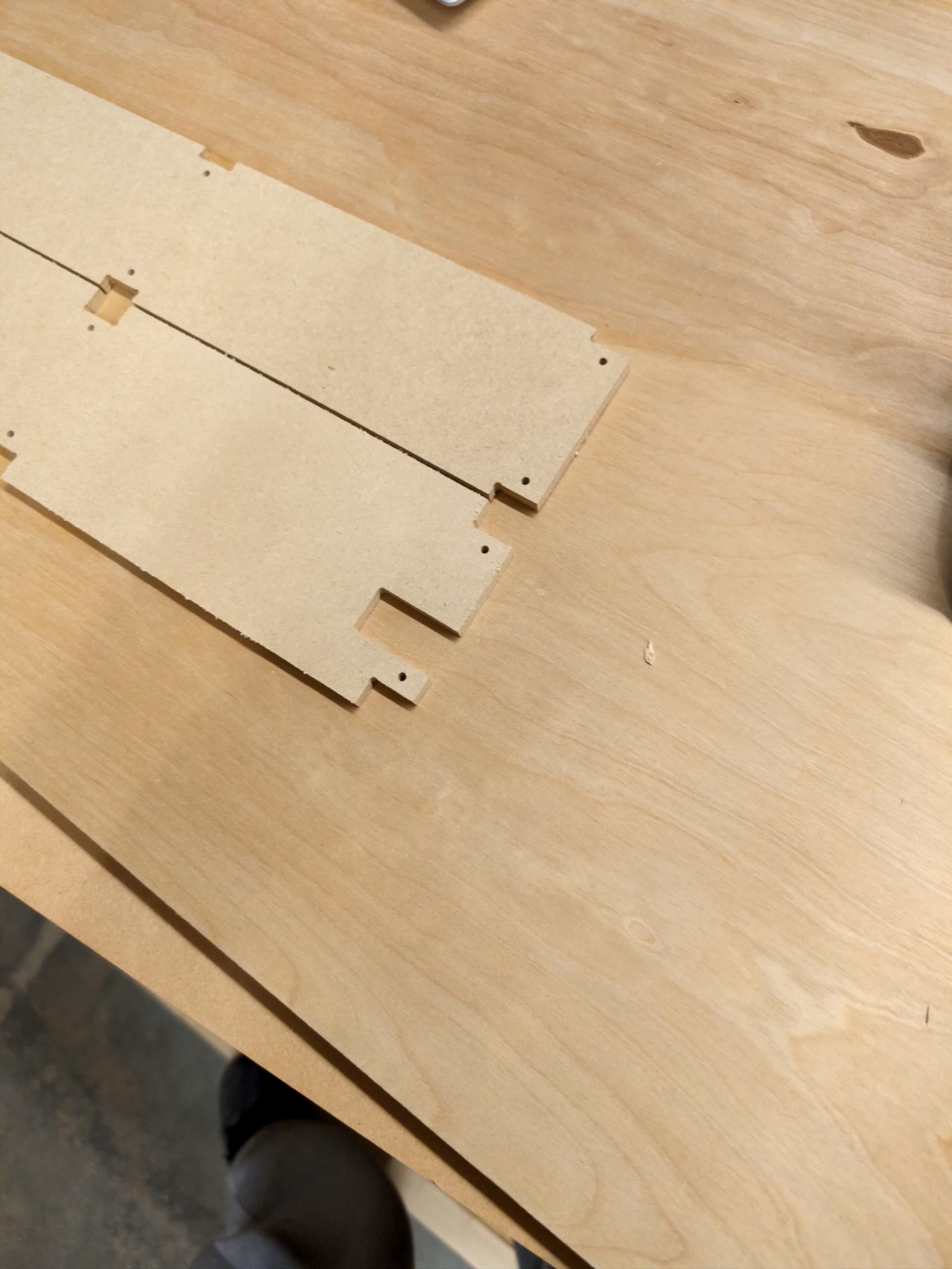
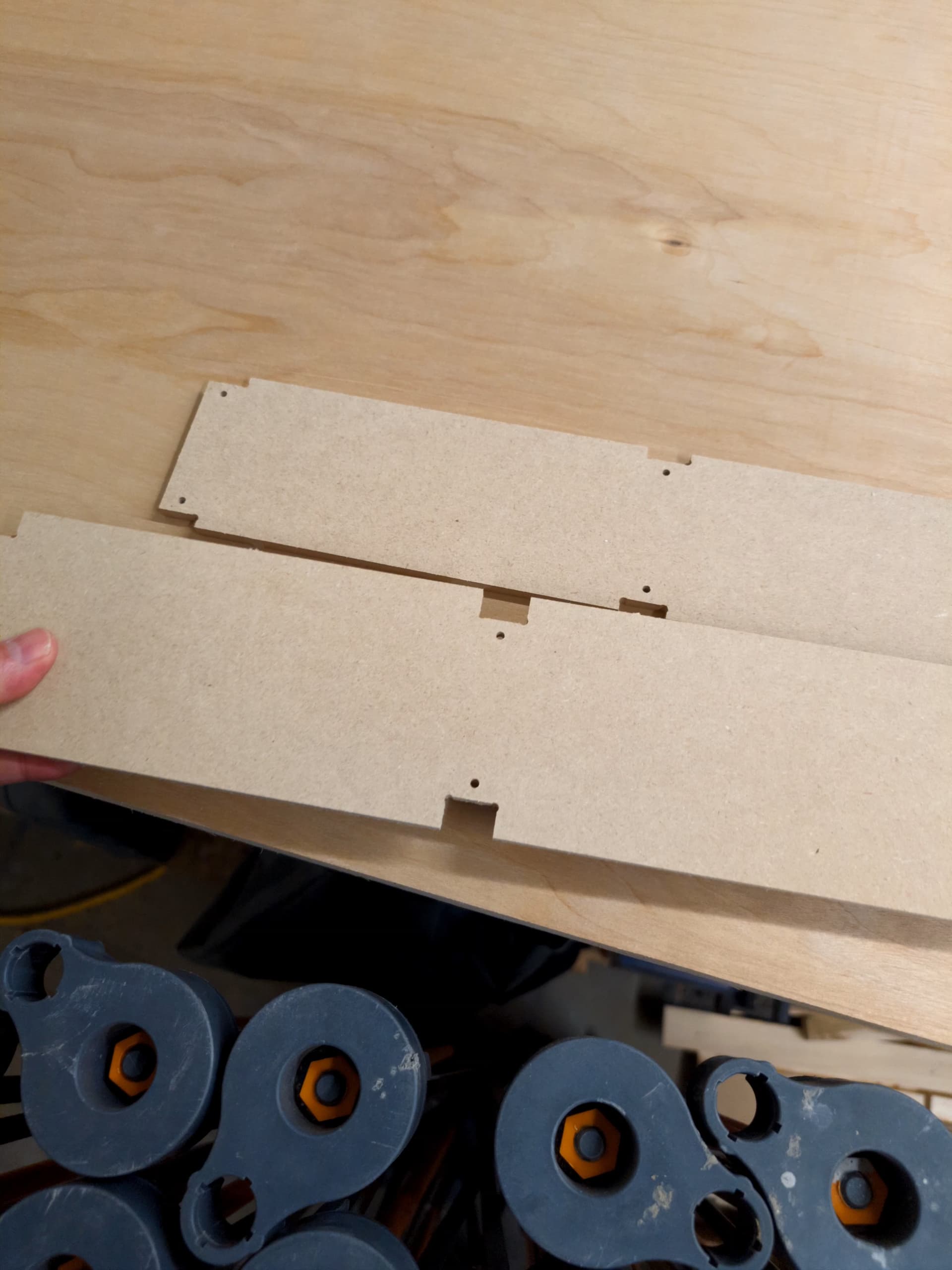
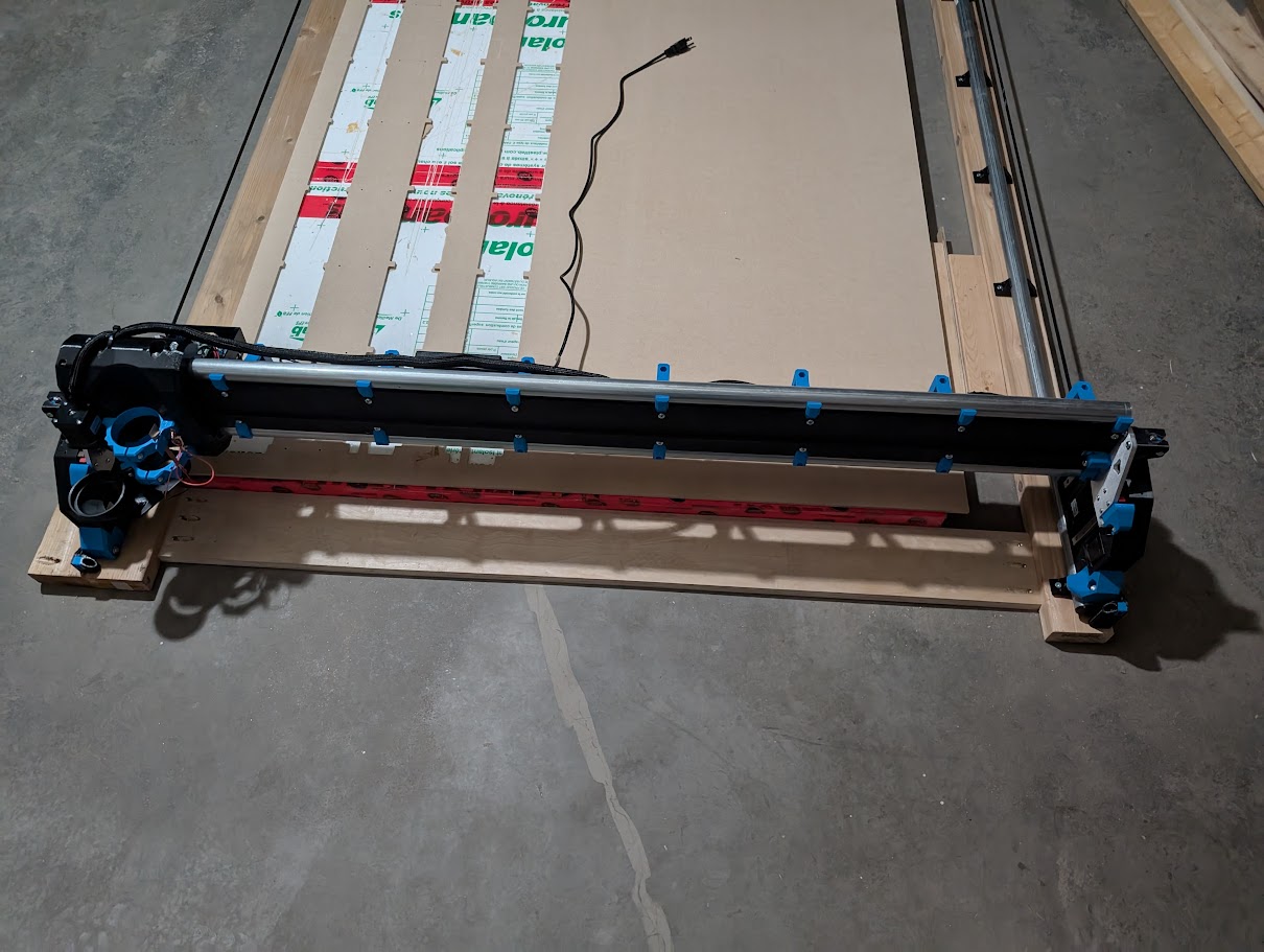
But I’m finally back at looking at my LR4. Last we left off i got the strut plates cut. So I got those lightly sanded and painted. Gantry completely stripped down, rebuilt with new struts, completely re-wired to allow for some future modding and the core now has a touchplate.
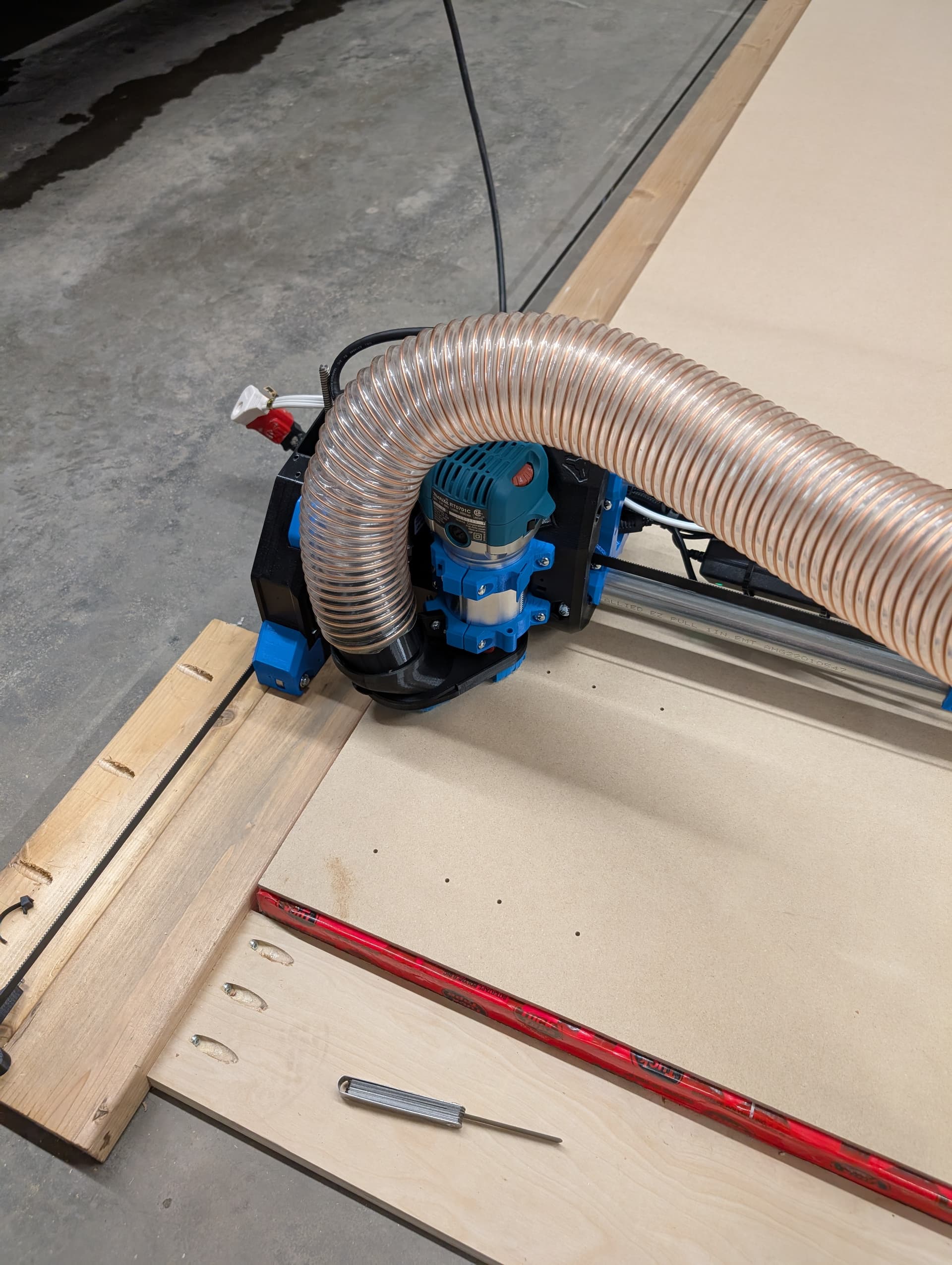
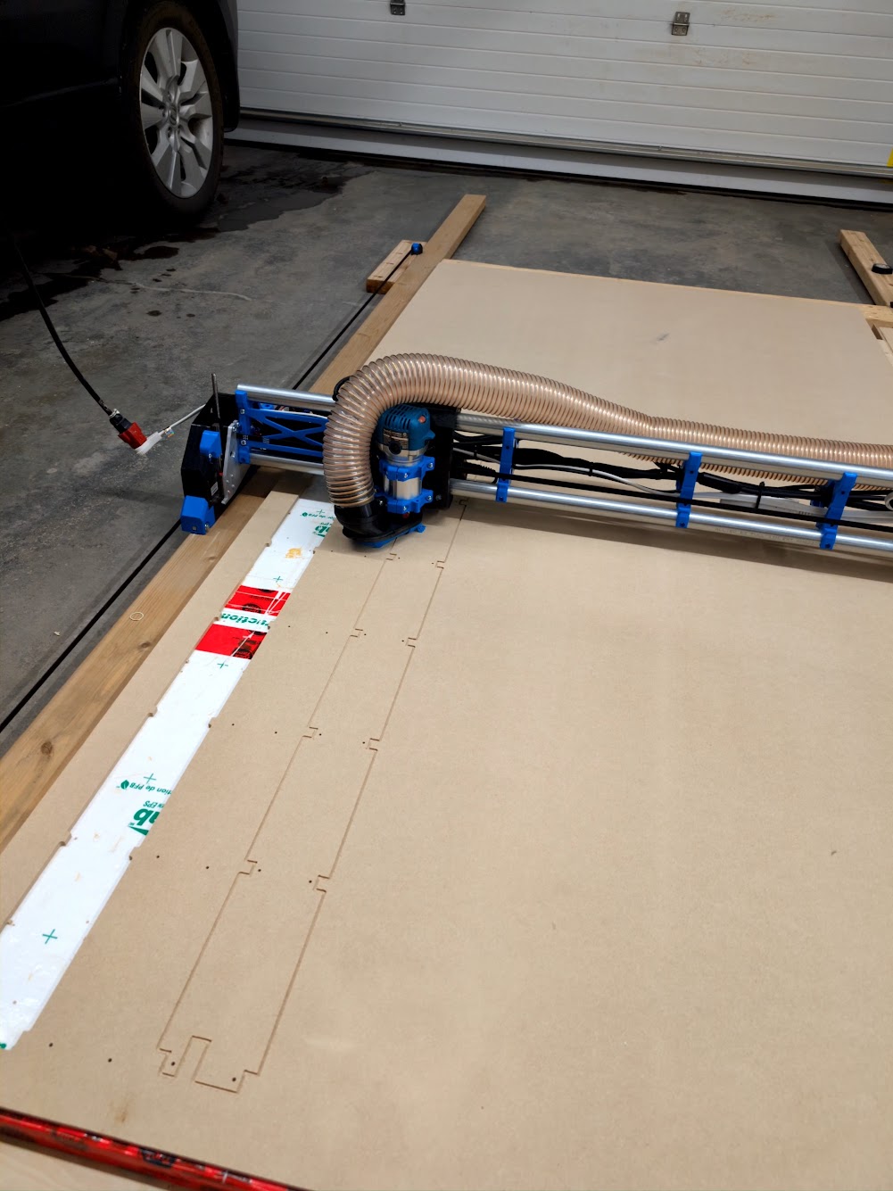
Its now re-installed onto my garage floor, and running again. I seriously need to get the table together and get my parking spot in the garage back. I’m tired of scraping frost off my windshield every morning!
That’s fairly close to what i have going on, just have a softer white foam board I use for my track saw with my centipede table to rip sheets. Its was definitely only a temp flat surface with two goals, cut the struts and then cut the torsion box out out of 3/4" shop grade birch ply. If it was more permanent yes, definitely would have used the two sheets of 1/2" MDF i have sitting on my sheet cart that will likely end up as soil board in the future.
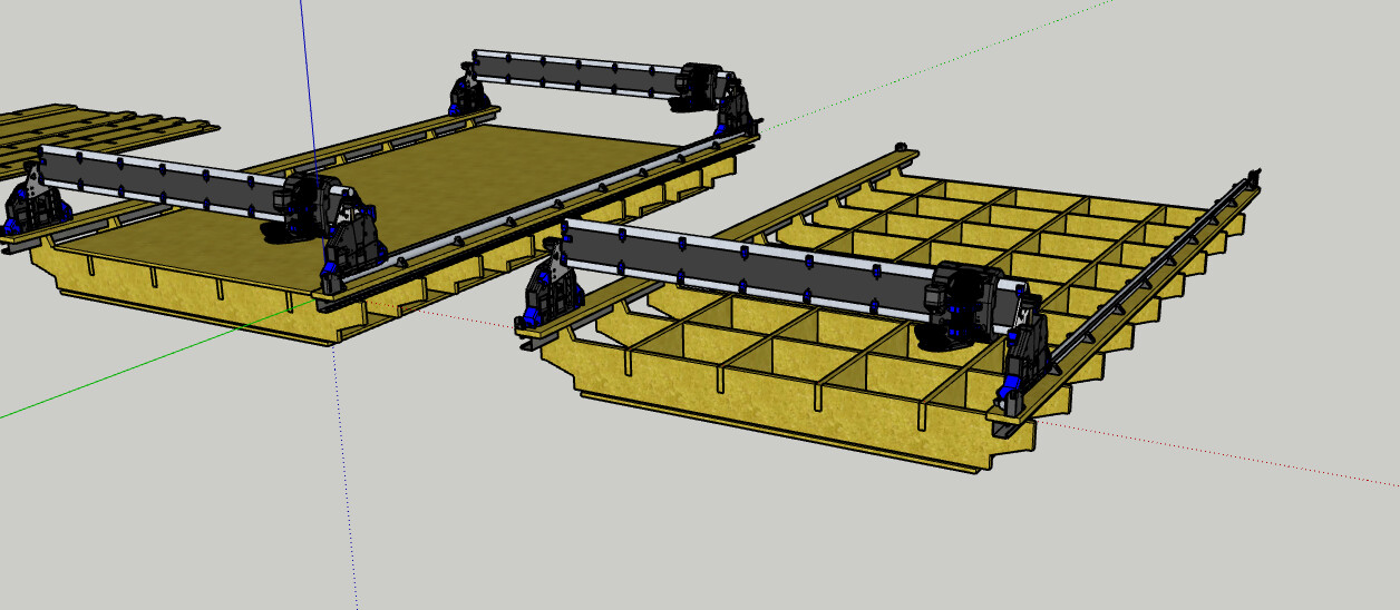
Current draft rendering plans for drop table (thanks Doug for some great ideas along the way)
Open for any feedback anyone has to offer. I think its overkill right now and might take it down to 3 Y-rails and drop 2 or 3 of the X-rails.
Once i move it to the permanent table, i have some additional electrical upgrades, better 24V DC distribution, might replace 24V brick with a 24V 3D printer power supply, looking to also add undermount LED lighting i found on ali express (will also be adding these to my shop cabinets). I’m currently 3D printing some clips for the lighting to ensure the double sided table never lets go and gets caught in the spindle.
The rest of the table will need to be build and will likely integrate some storage drawers for spare parts and pieces and tools.
The shop itself is in a 2 year long dust collection system overhaul where I’ve had all the parts and none of the will to get my single stage dust collection converted to a two stage dust collection system. Its only 2 years long because i’ve lacked the motivation to complete it, probably a Christmas time project (again thanks Doug for your posts inspiring me to finish the plan and get that done). For the dust collection on the CNC, I think i’ll feed the 2.5" from a 4" line above the table. I printed a 4" to 2.5" movable coupler than seems to move about 30 degrees while allowing for full 360 degree rotation. Still have to try it under vacuum to see how it moves. Anyways off to work, looking forward to any suggestions or ideas.
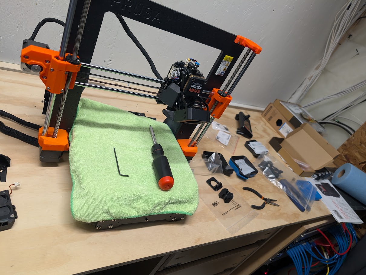
And for the fanboys, while I was sick, I got this upgrade completed! And will likely get the MMU3 reinstalled over the Christmas break too. NOTE: MK4S upgrade LCD kit is NOT compatible with the prusa enclousre. Working on solutions there to find or design a drop plate to allow the doors to close.
Looks great so far. ![]()
There’s no drop in your table though. ![]()
It most definitely should be, I think I read the instructions for the installation before. Might be wrong though.
Looking good! Thanks for keeping us updated!
My solution is still a year off I suspect - the Core One upgrade! ![]()
Meh, mine took more than thirty years, then I solved the problem by sticking the single stage collector in a lean-to outside! ![]()
I’m really loving watching progress by the way.
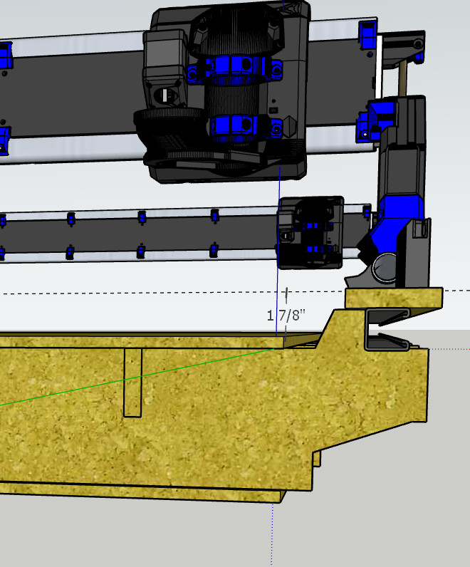
Phillip am i miss understanding the concept of drop? i have almost a 2" drop from the spoil board to the top of the Y rails?
Was planning to put final touches to the drafting today and start the cutting tomorrow. If i have completely missed the mark please let me know!
A drop table is usually a table where you can lower the spoilboard, the other option is to stack several boards and then remove them if you need the height. Yours looks like the second kind? This might not be too accurate though if you don’t plane the lowest level before stacking the boards.
The way it is now the collet is not going to reach the spoilboard if it’s on the lowest level, so cutting with 3.175mm endmills is not really possible (if you want cut something through that is).
Was that understandable? I kind of feel I am not explaining myself well. ![]()
Very much! Thank you. Definitely was planned for the second option. Will play some more and delay my plans! Thanks Phillip.
That could work if you put one board at the lowest level, take a long endmill and plane it. Then stack the other boards, they should match the lowest board now and you can just take them off if needed. This option needs a lot of stacked boards though. For a full scale LowRider I don’t have a better idea regrettably. ![]()
Or you can get very long endmills to reach the lowest board if you want to cut through (if you want to engrave a 4’’ piece of wood it would not matter), sacrificing rigidity then though.
It’s really a tough call.
The plan was to start with a couple sheets but you have definitely given me a great ah ha moment. I think I’ll change my plan for now and do something more straight forward then modify/build something new in the future.
I’d just leave the “riser” for now. You can always add strips of wood later to make it heigher. ![]()
I’m using a bambu x1 most of the time but I keep the prusa going for backup and my kid likes to have their own 3d printer.
Anyway I upgraded to mk4s and found these mounts were the simplest to deal with lcd blocking the enclosure doors.
Thanks Travis. Ive got a mount now that drops it. I actually printed the exact ones you linked there first but couldn’t get the square nut into the part (tolerances are too tight or the designer has narrower nuts) and I didn’t feel like tinkering so ended up printing this one:
Haven’t installed it as I still have to take apart everything again to get the mmu3 back working with the upgrade. But it dry fits and seems to work and allow enough clearance for the doors to close.
Might just leave the LCD attached to the printer inside the enclosure since prusa connect has gotten so much better. Save some space in the inside office and not catch myself on the LCD case all the time.
I guess my nuts are narrow, they fit nicely.
I actually use Prusa Link for most prints - it works really seamlessly, but I find it easier to remove the USB stick occasionally to batch delete stuff. My LCD has been in the enclosure since the Mk3 but I rarely print with it at high temps (more than 40 degrees).
Alright been a long while since an update. After getting over the last cold, I somehow picked up COVID right before christmas and only just starting to feel human again.
So update, I’ve abandoned my table plan for now and done the standard 97x47 LR3 table. Got everything cut out, and boy was that a learning curve on the software, the machine and now have pre-flight checklist before all cuts now to ensure a few things. I’d say the biggest lesson learned is the cut height on Ryan’s 1/8" endmill is only about 13-14mm and trying to do a finishing pass at full 18mm doesn’t work haha. oh boy that left some frustrations but good learnings!
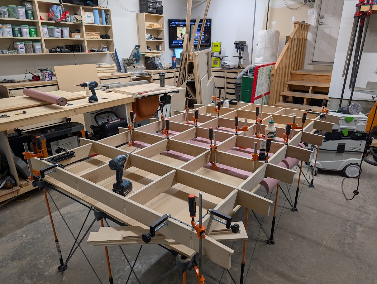
Here is where the table current sits in partial glue up mode. Not enough clamps… never enough clamps!!!
And yes there are so many not finished projects along the way. But so happy to have my LR4 off the garage floor, its -20C outside and I’d sure love my parking spot back!
Thanks again to all those who have helped along the way. So excited to almost have this fully functional!
You must be using this one…
Next time you order some bits from him, try these…
They work much better for me. I am quite often cutting 3/4" plywood with them