Hi all.
I’ve got the Dual Endstop firmware and am using an endstop per motor (as shown in the v1 build doc) as well as the touch probe.
When I connect everything on the bench (prepping before final build) I see “odd” behaviour i just wanted to check whether is right or not.
The SKR Pro has a a red light for each motor (next to the pin header connection) that comes on when a limit switch for each x / y / z axis is triggered. if you have dual endstop firmware, then you also get a red light trigger when y2 or z2 is triggered.
ok so far, all making sense and normal…
So on to the perceived issue and question…
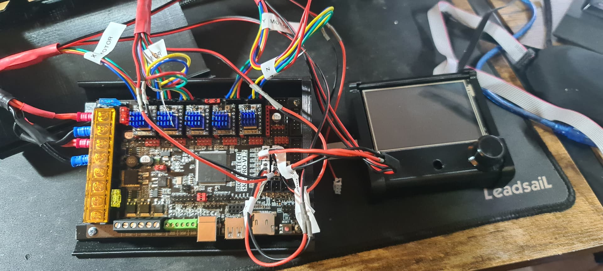
The skr pro has a driver that has 2 red jumpers in the pin header, The pin header is the 4th pin header from the motor power wiring from the Power supply connections.
Now when i connect all my limit switches and trigger them one by one, the 2nd Z switch triggers a red light on the 4th pin header, the one with the 2 red jumpers from the factory. (see image with header circled)
the question? isn’t it supposed to trigger the 6th pin header which would be Z2?
i’m going to check the marlin config / pins.h & skr_pro_common.h but… would assume the pin headers are (starting from the PSU input side)
X, Y, Z, 2xred jumpers, Y2, Z2, unused (see image)
lastly, for the Low Rider 3 build, using the SKR v1.2 Pro with dual endstop firmware, could you please confirm limit switch and touch probe pin headers? I’ve included what i think they are (see pic) Just want to make double check as they don’t seem to correspond to the build doc… (although, to be entirely fair… it’s entirely like me to have gotten myself confused, so may well be me doing something daft, hence asking for the clarity 

thanks in advance,