Pick up a diamond blade made for the stuff, and your circ saw will glide through it no sweat. It’s great for certain uses, but this is not one of them.
1 Like
Hardibacker is cut on site using a box cutter- score the line, and snap. It’s easier than drywall
I learned that after my construction company owner neighbour watched me ruin two circular saw blades on a single cut. He came over, scored a line using a drywall square as reference and snapped it in 20 seconds. Laughing while he did it
3 Likes
Hey, on this page:
https://docs.v1engineering.com/lowrider/#strut-plates
…I just now I tried to click into the “CAD / Fusion 360” link for the 4’ strut, and Fusion 360 said “Model is empty” (said there was no geometry, nothing to show).
By contrast, the link for the 2’ version works fine.
Broken one (4’):
One that works (2’):
Okay Learned something new there. I had the model rolled back to the first sketch. So there was no geometry yet, just a sketch. I saved it rolled forward now, same link.
1 Like
That’s what happened when I tried to share my parameterized model, too. With just the sketch, Fusion doesn’t share anything.
2 Likes
Hey, how are you all doing the attaching of wires to the end stops? Push on? Crimping? Solder? If crimping or push on, what type of crimp or push sleeve? Link?
Hi Doug - the connectors elsewhere are called Dupont Connectors they are tiny and require a bit of care to crimp - but you soon get in the swing of things with them. The link is for a random box and crimping tool - I bought something similar for the LR2 so I could shorten all the looms and make things really tidy, and have enough left over to last me till the LR800 comes out.
1 Like
Hey I think you might’ve misunderstood me. The wiring approaching the end stop has Dupont connectors. I have a batch of those and the right crimping tool for that. The problem is the lead coming off of the end stop is not the pin made for a Dupont connector. It is a much wider strip of metal with a hole in it. It’s the kind of hole that’s made to put wire through when you are about to solder a wire onto the lead. I definitely can do some soldering, but for usage such as 3D printers and CNC machines where there can be heat involved, I think I read that solder is not the best solution as it could become hot and soften.
I should add that I’m using end stops purchased from V1. I imagine there might be other end stops that do have pins coming out of them that are suitable for Dupont connectors. These are not.
1 Like
Perhaps it’s more explanatory if I ask this another way.
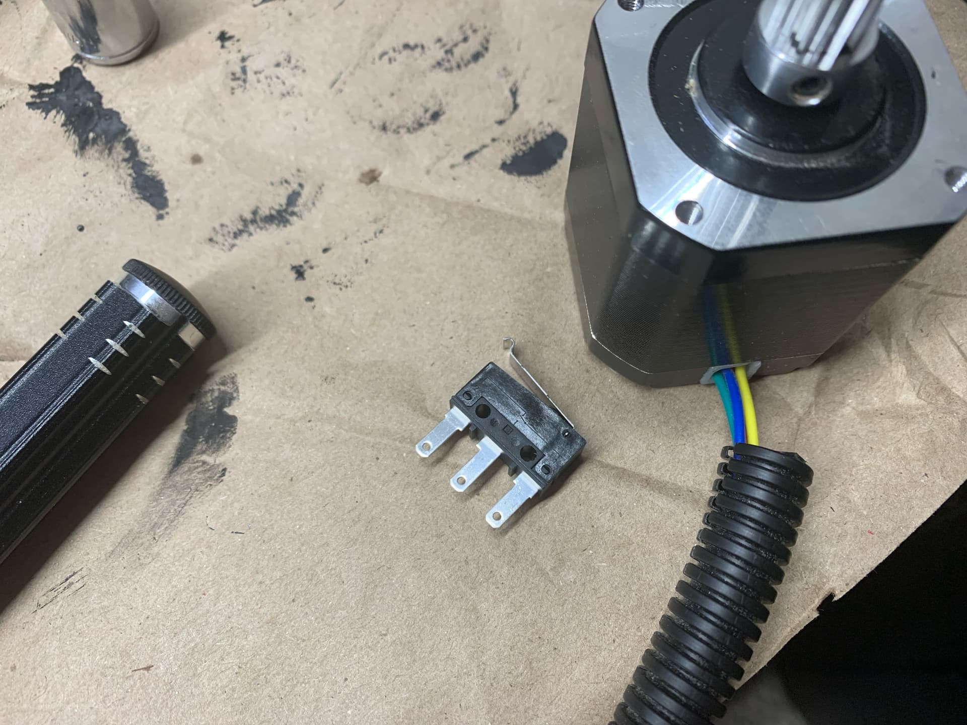
What kind of connector is shown in this photo, connecting the wires to the end stop?
.jpg)
It looks somewhat like what is shown in this amazon listing as a “female bullet” — Amazon.com
If that’s what it is, I’m wondering… is there a male bullet hidden from view? Or did Ryan just press/slide a female bullet onto the lead? Or did he crimp a female bullet onto the lead?
More likely Female Spade from that listing, with a better (or more thorough) insulating shroud. If you squint you can see that the middle contact in the end stop is a male spade style tipped mostly edge-on toward the camera.
2 Likes
@billnye Thank you! Will go shopping.
You can get them at auto parts stores, in case you want to make sure you have the right size.
2 Likes
Couple more tidbits. The “spades” on mine are turned 90 degrees from the ones in the above photo. My end stop’s spades are 0.5mm thick x 2.8 mm wide. See pic:
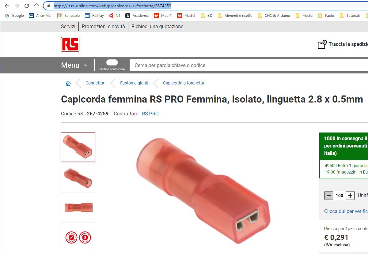
I don’t know if this can help you. In Italy we find these: https://it.rs-online.com/web/p/capicorda-a-forchetta/2674259
2 Likes
If you have the ability, I would solder them on (the smallest connection and stongest). If you want, these are the female spade connectors from that picture, https://amzn.to/3MWGgcO.
3 Likes
Possible typo. I could be mistaken, but I think the photo here:
.jpg)
… shows nuts in, bolt heads out.
Yet the page here:
https://docs.v1engineering.com/lowrider/#wheels
…says “Wheels installed, Heads in Nuts out.”
Am I looking at it wrong? Doesn’t the XZ plate face inward?
Another possible typo.
On this page:
https://docs.v1engineering.com/lowrider/#printed-parts
…the printed parts list says:
| 1 | Bearing Wheel Bracket Front | 30% | * See note below - Optional Version | Link |
|---|---|---|---|---|
| 1 | Bearing Wheel Bracket Rear | 30% | * See note below - Optional Version | Link |
…But wouldn’t there need to be 2 of each, instead of 1 of each? Two fronts, one for each side, and same for rear?
That is meant to be screw heads in on the wheel brackets.
No, I don’t think so. The bearing brackets you need one of each, for the wheel brackets you need 2 since they are the same. Still using a rail on the other side.
1 Like
Ah yes, no bearing wheels on the rail side. Duh.