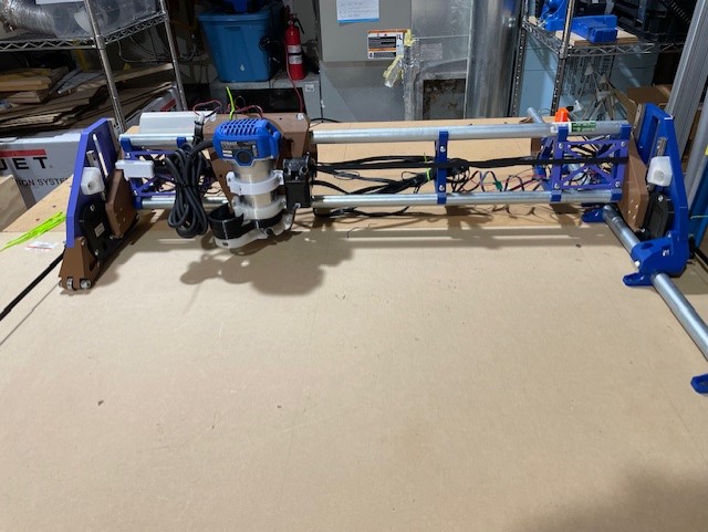
Well, here’s my go at it. The worktable is 6’x4’ roughly, but I’m only using 4’x4’.
My assembly went together fairly easily, other than having the wrong pulley on one of the y-axis motors initially.
I will square it up in this configuration, then worry about cable management after I crown and cut my struts.
One of my goals is to utilize the 8020 extrusion that rims my worktable, so probably designing some timing belt holders and pipe brackets for that purpose.
I’m using a jackpot board, while I’m just jogging around on my phone. I love how quiet that thing is.
Looking good, I’m at the squaring portion of my build too, tried to do it on the floor but my floor is way too unlevel so I built a table and it’s all assembled now!
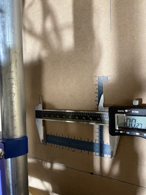
Great start! I notice that some of the strut brackets seems to be spaced a little further apart than the recommended 8", but presumably that is because of the temporary struts. If you keep them for a while, you may want to print another bracket, but for just cutting the permanent struts it should be fine.
Looking forward to more pics as your build progresses!
Yah, I printed two more, then thought, ‘meh, I can wait’. So, I’ll put one more in when I do the strut thing.
I also have aluminum and MDF plates waiting on the side. I figured I’d go with the printed stuff first, and see how it goes. I might end up just making two machines.
Looks good. I’m at about the same point just an hour away in Duvall. I’ve been debating some extrusion based table also. Will be curios to see how yours goes.
I’ve managed to get the homing of all axii going. I took a slight detour as I had wired up the Jackpot as if for the MPCNC (just for the end stops), which of course doesn’t work. After looking at the second picture on the controller board page, I got that sorted, and all of them home the correct way.
My work envelope is roughly 3’x2’ at the moment.
I did some ‘drawing’ by jogging, and got a pen to roughly sketch out some boundaries. I think it’s time for my crown test.
just for shits and grins, I’m using “the new technology” to help me generate gcode. So, I gave ChatGPT this prompt:
You
draw a circle of radius 50 starting at absolute position 200 200 using fluidnc. Raise the z-axis by 10mm before moving to the starting point, then lower the z-axis by 10mm to start. When finished, raise by 20mm.
and it generated:
G17 ; Select XY plane
G21 ; Set units to millimeters
G90 ; Absolute positioning
; Raise Z-axis by 10mm
G0 Z10
; Move to the starting point of the circle
G0 X200 Y200
; Lower Z-axis by 10mm to start cutting
G1 Z0 F500 ; Assuming F500 as a safe feed rate for Z-axis movement
; Draw a full circle with a radius of 50 units
; Assuming the center is at (250, 200) relative to the starting point (200, 200)
G2 X200 Y200 I50 J0 F1000 ; Assuming F1000 as a safe feed rate for the XY-plane movement
; Raise Z-axis by 20mm after finishing
G0 Z20
That seems reasonable enough. I’ll add in the pre/post processing stuff, and it should be good. This is another way to go for simple stuff.
before that, I asked if it knew about fluidnc, which it did. So, I think I can train up a GPT that knows fluidnc, and have it help me generate various gcodes.
the biggest challenge with it right now is that I’ve created “CNC Buddy”, which is a specialized GPT for configuring things with fluidnc firmware, but OpenAI is a walled garden. Although I pay a subscription, YOU can’t play with my expert unless you also have a subscription… They make money off this arrangement, but those who create the ‘expert’ don’t. That’s a business model worse than YouTube.
On the plus side, I was able to demonstrate to my sister that she could control my Lowrider from her cell phone, and she’s neither a techy, nor a CNC enthusiast.
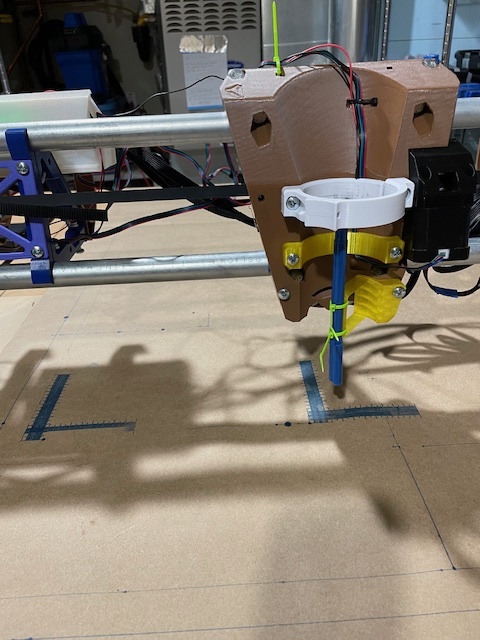
I finally got around to printing the pend holder, instead of zip tying to the hose holder. That’s a much better way to go.
I had a problem with my two z-axis motors being out of adjustment. The screws were not seated in the couplings exactly the same on both sides, which caused one side to be higher than the other.
that’s all sorted. I guess I’ll try a crown tomorrow.
Jogging around, drawing with a pen is fu and all, but let’s get serious… The biggest challenge I had was unmounting that pen setup, and remounting the tool holder. The smallest nuts in the most hidden place (behind roller bearings on the rail) made it necessary for me to take the whole x-axis off the rail to sort stuff out, get the nuts back in position.
Note to self, definitely CA glue, or otherwise lock those nuts into place.
Other note to self: come up with a better tool mounting mechanism that doesn’t require ever having to take these nuts out again.
Got it all sorted, ready for more spinning tool of death.
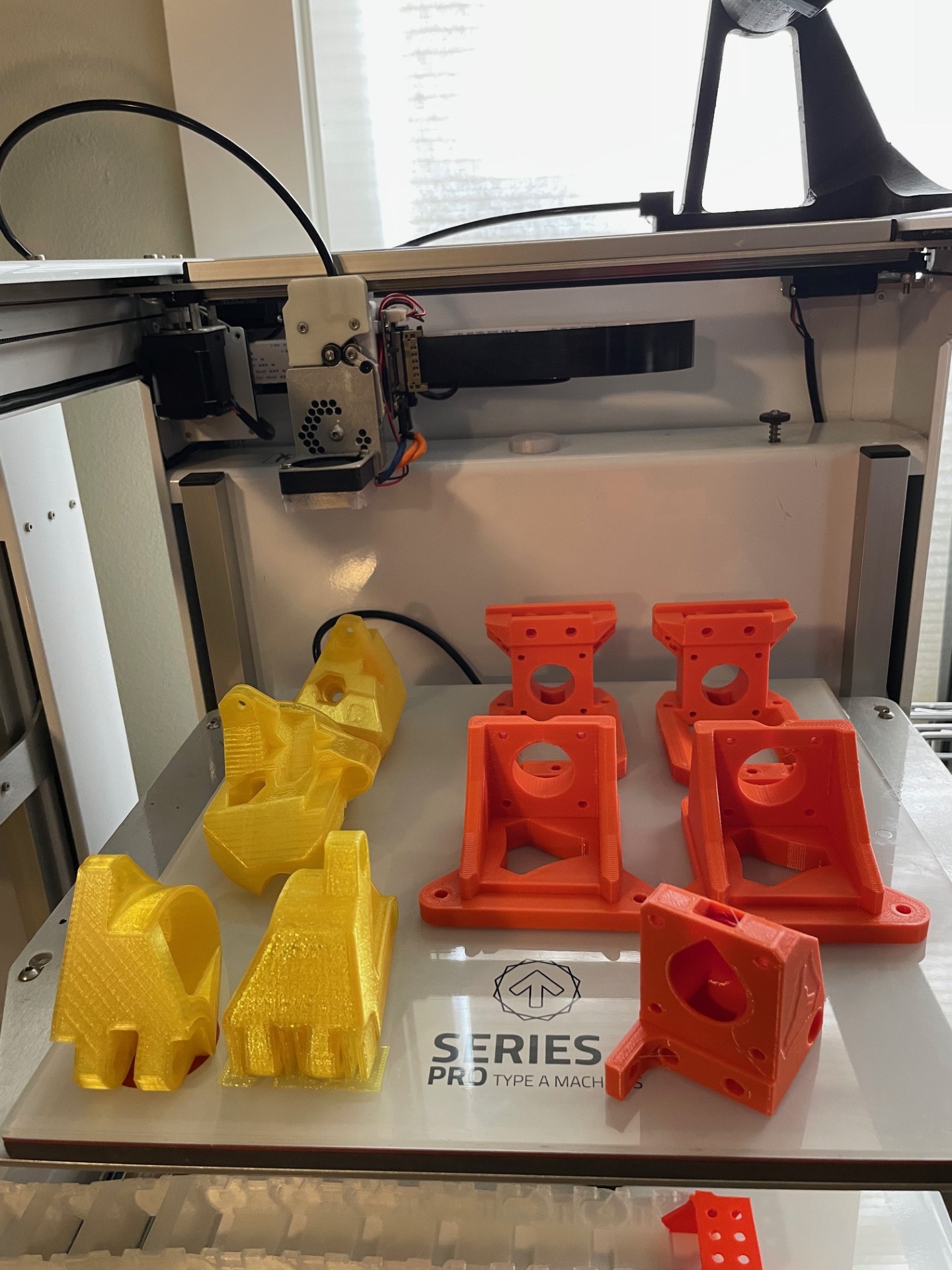
In the meanwhile, since I’m building the Lowerrider not strictly for production, but for experimentation, I thought it prudent to print off another set of parts.
These, plus a core (not not in picture), are all done in various forms of PETG (HatchBox, Prusament, eSun PETG).
I know PLA is the preferred material, but that’s what the experimentation is for. I think the PETG will be a good usage on the Core because it’s supposed to flex a bit to join the pipe.
We’ll see how it goes. I’d really like to try some Prusa PC blend, but that stuff’s really expensive in comparison.
At any rate, now I will have the option of two gantries to play with, so when one is down, I can swap in the other one.
Put the spinning tool of death into the tool holder.
Put the 1/8" collet in (Kobalt router)
Confirmed the probe actually works for the first time
Notes to self:
Take note in the instructions, when you generate your crown g-code, make sure the gcode for probe detection isn’t in the preamble, or you’ll be slamming pen into surface, and grinding motors.
I have some nice carving bits from a previous life, so now I get to carve
dust has been generated in anger…
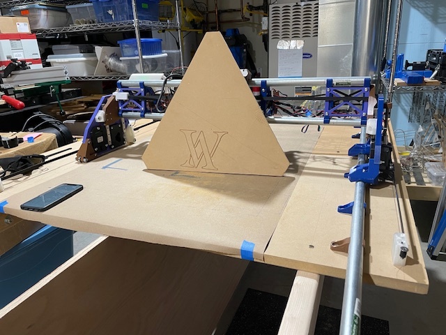
This is my “crown”, my company logo.
The flaw there came from the work “holding” being loose at the beginning.
1/8" 45 degree carving bit. 2.5mm depth of cut. No real problem. I did notice the cobalt router doing its random speed adjustment while it was sitting there, but the whole thing just worked out correctly, including the initial probe sensing and whatnot.
Concept has been proven, now I need to build the real deal. Table needs to be extended to full size (8’x4’), spoil board, work holding, etc. That’s all a project in and of itself, but we’re headed in the right direction.
I’ll throw the 1/4" cutting bit in there and try to cut out something, like the yz plate, to make sure I can do more than just carve.