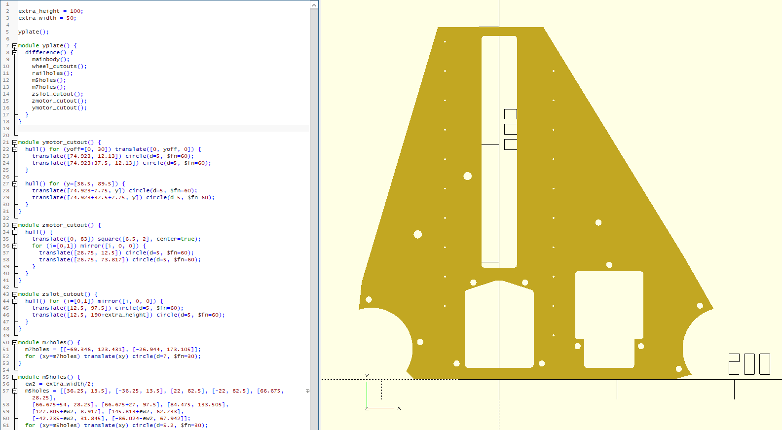
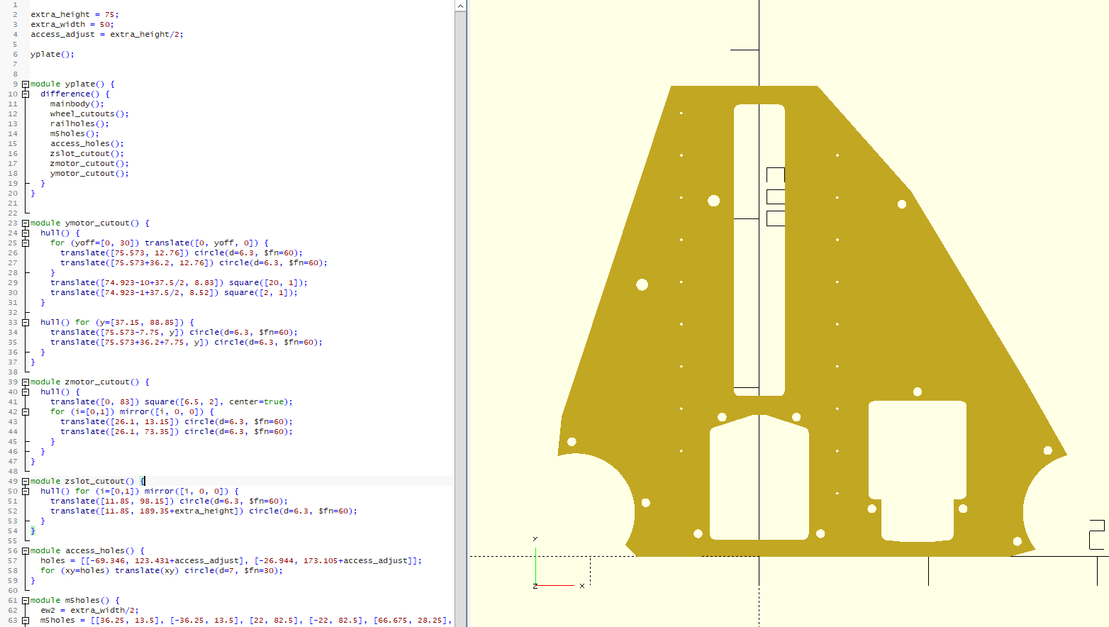
With mine, I found that moving the screw access holes on the left of that drawing up was also a good idea. I didn’t with my first draft, and it was awkward to get to the screws. Still possible, but moving the access holes upwards was a big help.
Edit: Oh, you’ll also need to have the Z endstop mount moved, unless you are running without.
Good call on the Z mount. Looks like the plate perimeter needs to adjust for that too.
How much should the screw access holes move? I’ll make that a variable, but I’ll take suggestions for the default height (which can be dependent on extra height or not).
I tried to strongly emphasize that this is intended for lightweight materials, so hopefully people won’t try to mill tall pieces of lumber and have a bad time.
I increased the height of mine by 50mm, so I moved the screw holes up by 50mm and the Z stop mount the same. This makes all 3 beam screws available near the top of travel. My first shot, I left them alone and it’s still doable, but you can’t reach the top screw at the same time as the other 2, so I needed to move it all the way to the top for the one screw, then lower it until I could get the other 2. Yes, I needed to adjust the perimeter shape. Kind of a shame, it means that the toe wheel/rollers don’t line up perfectly with the milled piece any more, but it still seems OK to me. I played with one for 300mm rails, but it looks ungainly at that height. I thought that the 200mm rail version was good enough, You can kind of see where I decided to make my changes. (The small holes here are 2.5mm because I thought I might get it laser cut from 12mm acrylic, and then I can tap the holes for 3mm threads.) TallYZPlate.zip (3.1 KB)
It’s going to depend on what you’re going to use it for. Going too high might make it tippy. But! If you put it up on risers, say something like a flattened 2x4 on edge, that should be alright.
My guess is that a bigger Z axis would still be close to the same at low Z heights. But no matter how you edit it, when you have the gantry up 10", it will be less stable. If you are cutting foam, it might be ok. But we won’t know until someone tries it. I am guessing it will be at least an order of magnitude less rigid at that height. But who knows for sure?
25cm/10" is huge, and I also worry about the whole thing tipping over at that point, or at least lifting a toe.
It’s definitely in the “experimental machine” realm. I wouldn’t say it wouldn’t work though. Stay safe.
If you wanted to carve a parabolic dish that’s 3 feet wide and 10 inches deep you don’t have a problem with the router or collet colliding with the workpiece, but on LR3 you do have the issue of the gantry. So while a large Primo might not need a long endmill to cut a deep bowl, the constraint is different for LR3 and a long endmill would be mandatory.
In the end there are fewer use-cases for a large range of motion on LR3. For operating on the top of tall workpieces you really need a drop table instead. The one exception might be foam.
When I first started reading on this forum, there came through a common understanding about how things such as Z height impacted cutting, and the impact of mass at the core. The longer I follow this forum, the less certain I am about this common “wisdom.”
For example, on Z height, I ran across this video of a Burly.
Look at the height of this machine, and I guess he is happily cutting guitar bodies.
Or take a look at Steve’s water cooled, 2.2KW spindle here. That spindle has to weigh a ton, and according to his later posts, he is getting great speed out of his machine. He is using some special electronics to achieve those speeds, but he is making it work.
My thoughts:
Never rule against one of these machines even with experimental features.
I expect we don’t often see the failure machines on this forum. People are more motivated to post their successes than their failures.
There are no apples to apples comparison of the impacts of things like XY working area, Z height, and core mass.
Mine is 128mm Z travel with the 200mm rails. To get 250mm, you’d need 325mm rails, that’s getting seriously tall. I think mine is pretty reasonable as an increase, but another 100mm or more and I’d be kind of worried about trying to cut anything more substantial than foam.
Now, that said, I’ve had my machine up pretty high with a long mill installed and it ran like a champ. (The DC doesn’t work well like that though)
Yeah, I worried that it would be too much. My current LR’s leadscrew is 40cm.
Haven’t used the full length, but it is comforting to have some additional space to ride above a workpiece.
I recognize I would need at least 10cm height (for a mold shape made from multiplex), 5cm for an object made in the shapeand some space to move above this. So I understand that I’d land around 250mm rails?
Dan, I decided to go with the 200mm variant as this seems to be the rail I’ll be able to order easily (without overpaying import taxes - otherwise I’d order immediately at V1, they are fairly priced imo).
Is there anything I need to keep in mind using your design, other then the shape of those wheel rollers?
My Y plates are really close to the originals, but were based off of a slightly older edit of them. There is a tiny arch in the bottom of the Y drive holder that I don’t have. This does not affect my build at all, and seems to be there to allow just a bit more wiggle room if your motor shafts are a bit longer.
Other than that, mine build just like the standard ones, just with a few more holes for the rail screws.
Great, then I’ll insert your version in the laser cutter!
The only downside I seem to have is that I will not be able to cut the small holes for the linear rails, only mark them, so those I’ll need to drill manually.
I might go for a bigger hole, probably 3 or 4mm to have some room for errors.
The linear rails holes are bigger so you have room to adjust but only if your holes in the plates are smaller and your screws are smaller. If you make the holes bigger you’d need bigger screws and you’d have less room to adjust.
Hi Doug,
In the end I managed to laser cut the holes (in 6mm Alu) as defined by Dan. Unfortunately, after tapping 5 threads my bit broke, probably because I didn’t align perfectly square as I notice the M3’s are a bit loose in those. I even think in some an M3.5 or M4 might fit.
As I will install nylocs I am not to worried about it, it will give me some more wiggle room to fit them. Although I confess that I bought a new bit and tapped the rest with a tighter fit. Not sure if I would recommend someone to tap that many threads in Alu as it takes some time to do so:)
It took me some months before starting to put things together:D
As an fyi for anyone willing to use this template.
I noticed the 2 holes, for being able to fit screws in the bracket, are a bit misaligned. The hole should be a mm or 2 more to the right for your screwdriver to fit properly.
As I was using torx I managed to fit them in, but for disassembly I will probably need to make the holes larger first.