Looking pretty darn good so far I am organized but I would like to shut some doors to not see stuff sometimes. It is going to look amazing with the doors on.
2 Likes
Way more organized than my workshop and garage! I’m so far behind I feel I’ll never catch up.
1 Like
Well there’s no point in having anything finished around my place. What would there be to look forward to tomorrow if there was?
An hour or so worth of fiddling with the LowRider can’t hurt anyone.
This is why as a rule I don’t upload models (including the “fenders”… they are coming!) without testing them myself.
I apologise to the half dozen or so who’ve already downloaded these and had to figure this out for themselves.
The bottom front “encapsulator” probably doesn’t need to be glued in place, as long as one of the two bolts have nuts on them they will stay happily in place, but I will eventually use a tiny drop of superglue just to stick it there, and perhaps a small drizzle of epoxy on the bottom nut.
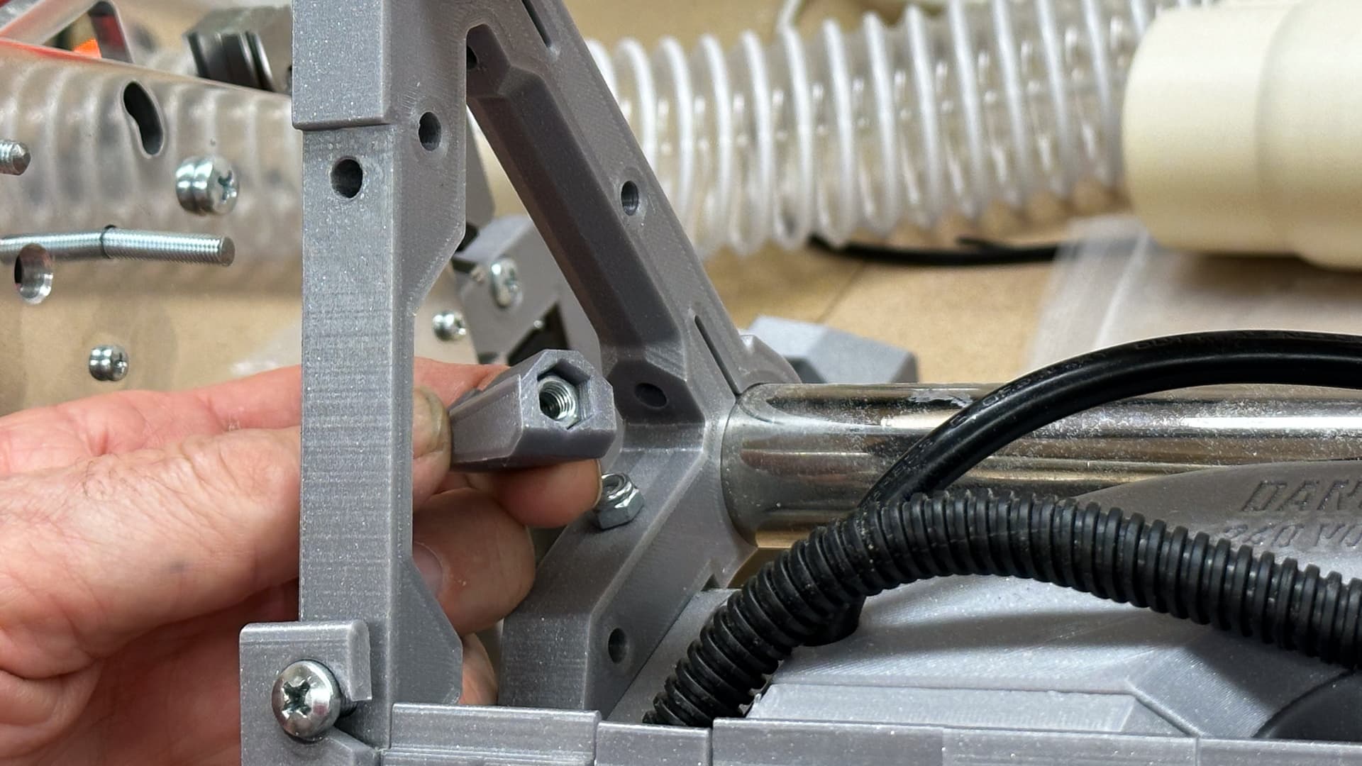
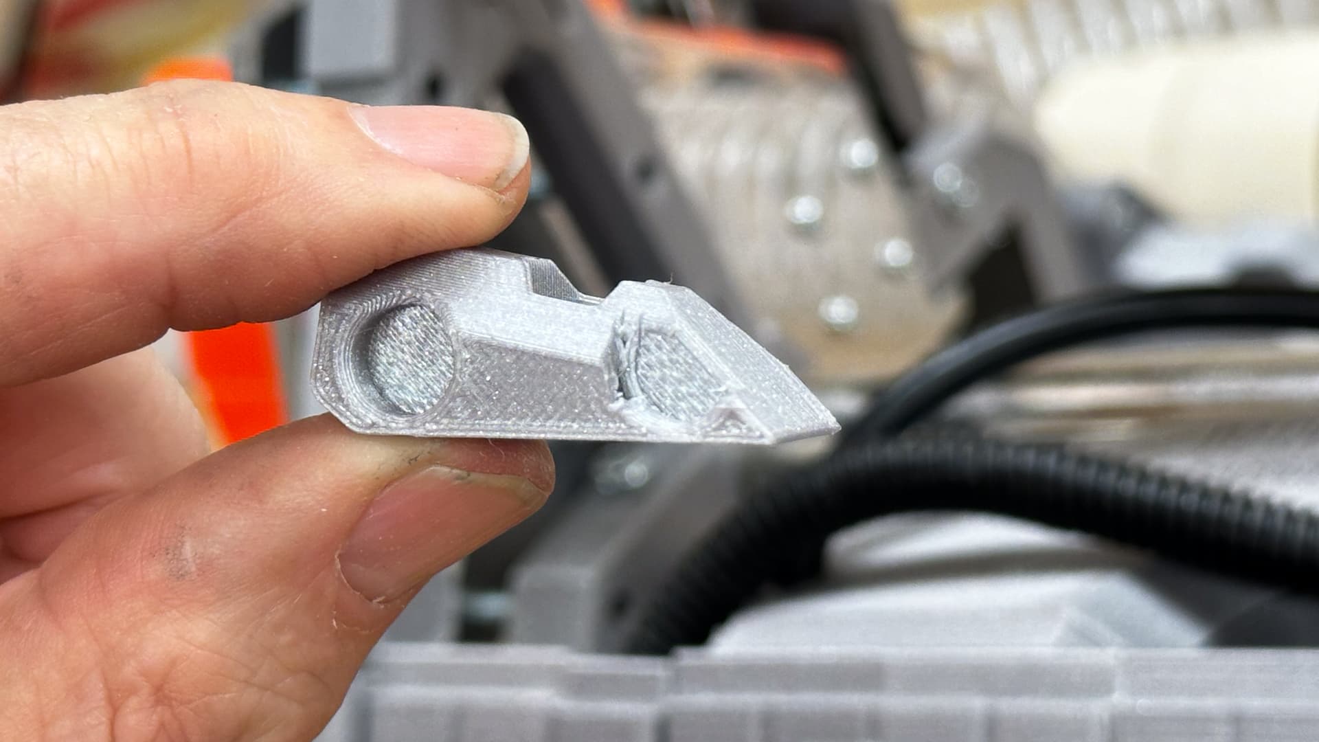
Sadly the cutout I put in place to allow for the screws missed by about half a millimetre. I’ll have that amended and uploaded later tonight.
In the meantime a tiny slice with a sharp knife will fix.
Since the router and vac mounts are likely to be in line for quite a bit of modification down the track, I’ve added a little epoxy to hold the nuts in place. This photo is really just to demonstrate how little - a tiny smear in one or two of the corners is more than enough. It’s not there to actually do any work, just to hold the nuts in place long enough to undo and replace bolts as necessary.

3 Likes
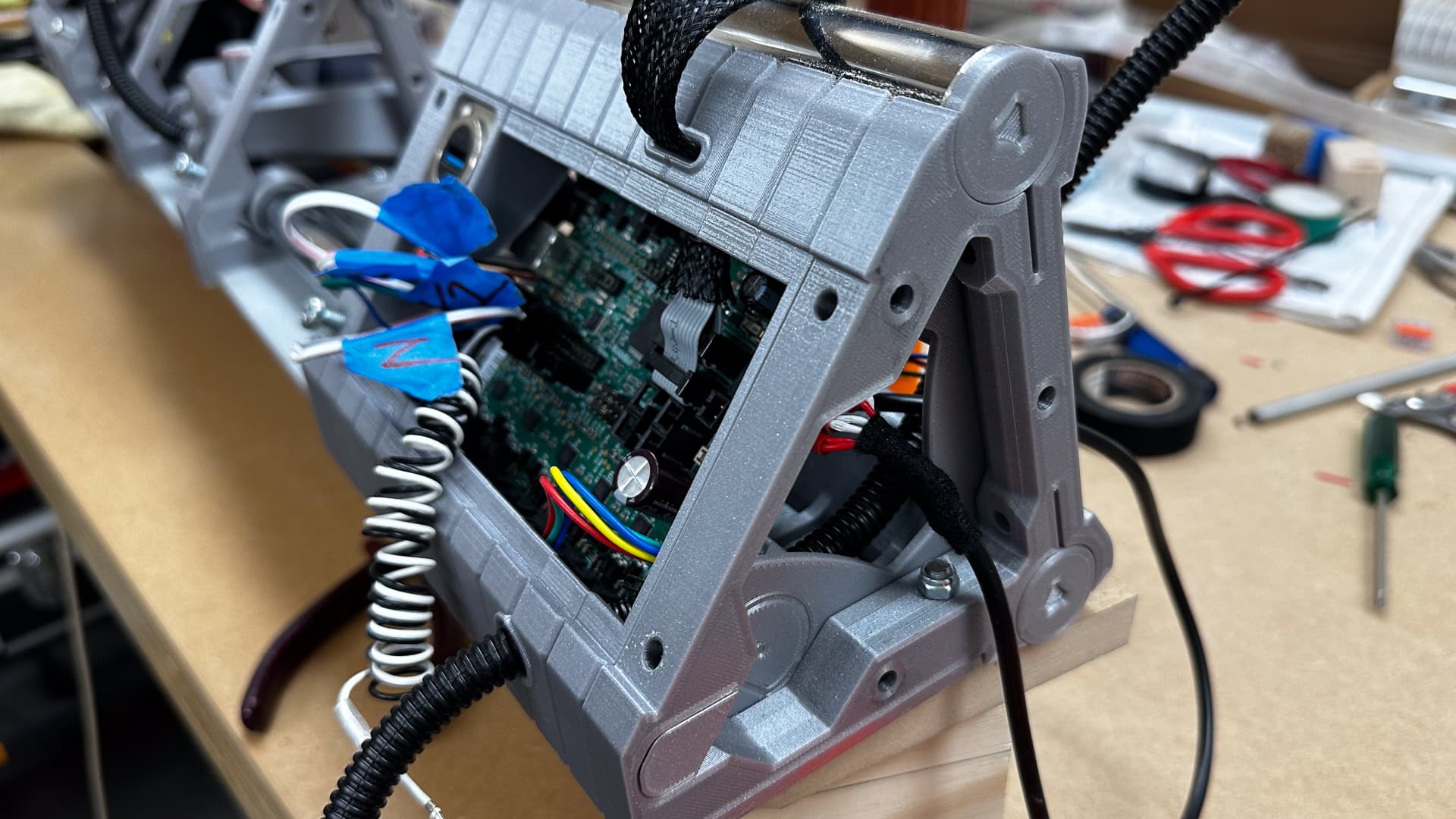
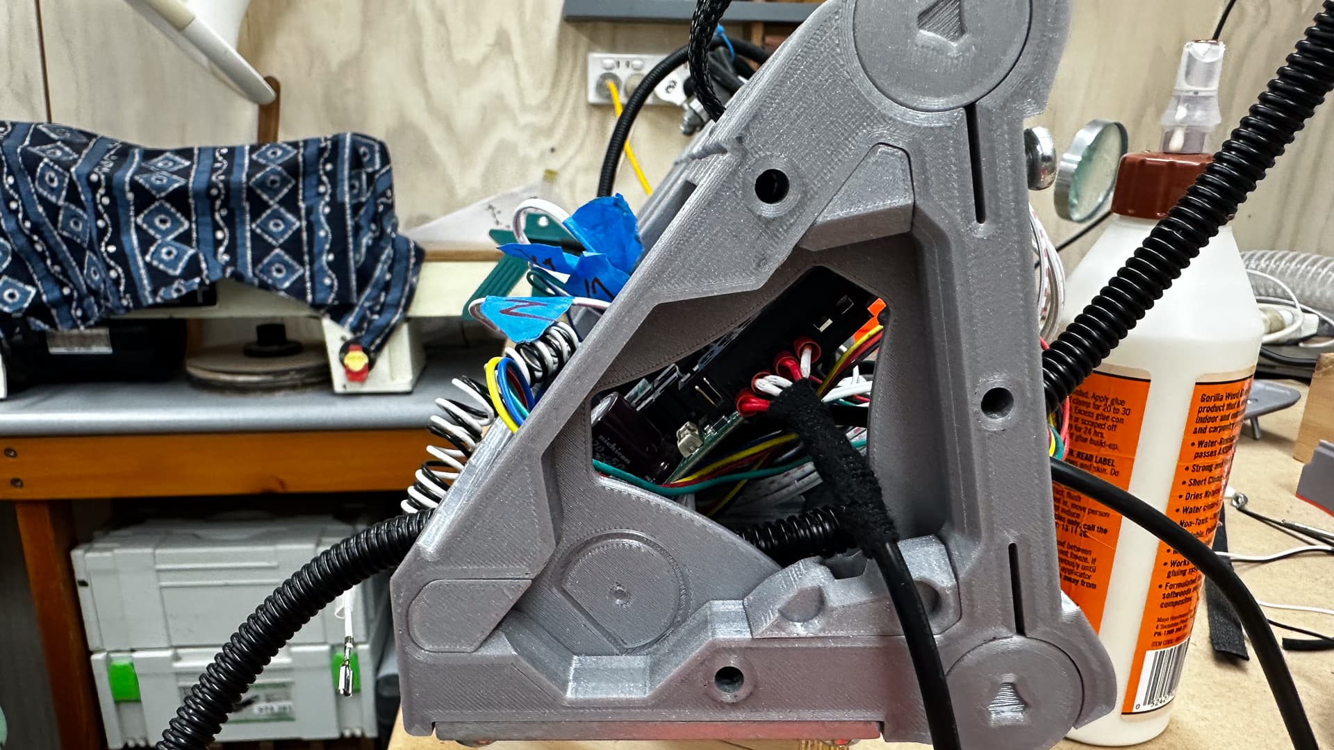
It started out as a good idea - fit the board into the strut, what could be hard about that?
Pretty much everything as it turns out.
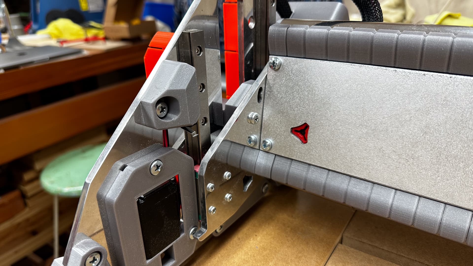
The end plates with the the board mounting brackets worked out well, but they made it impossible to access nuts after assembly. The space was just a little too squeezy to fit the USB cable so I made a vent hole and then had to extend it to cover the cable.
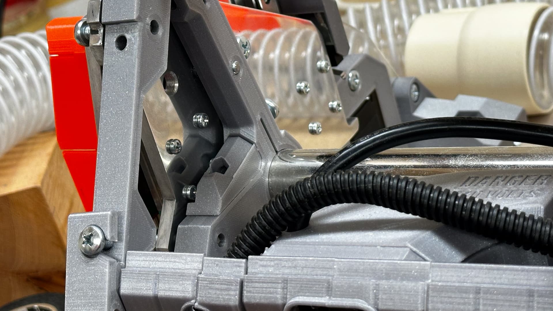
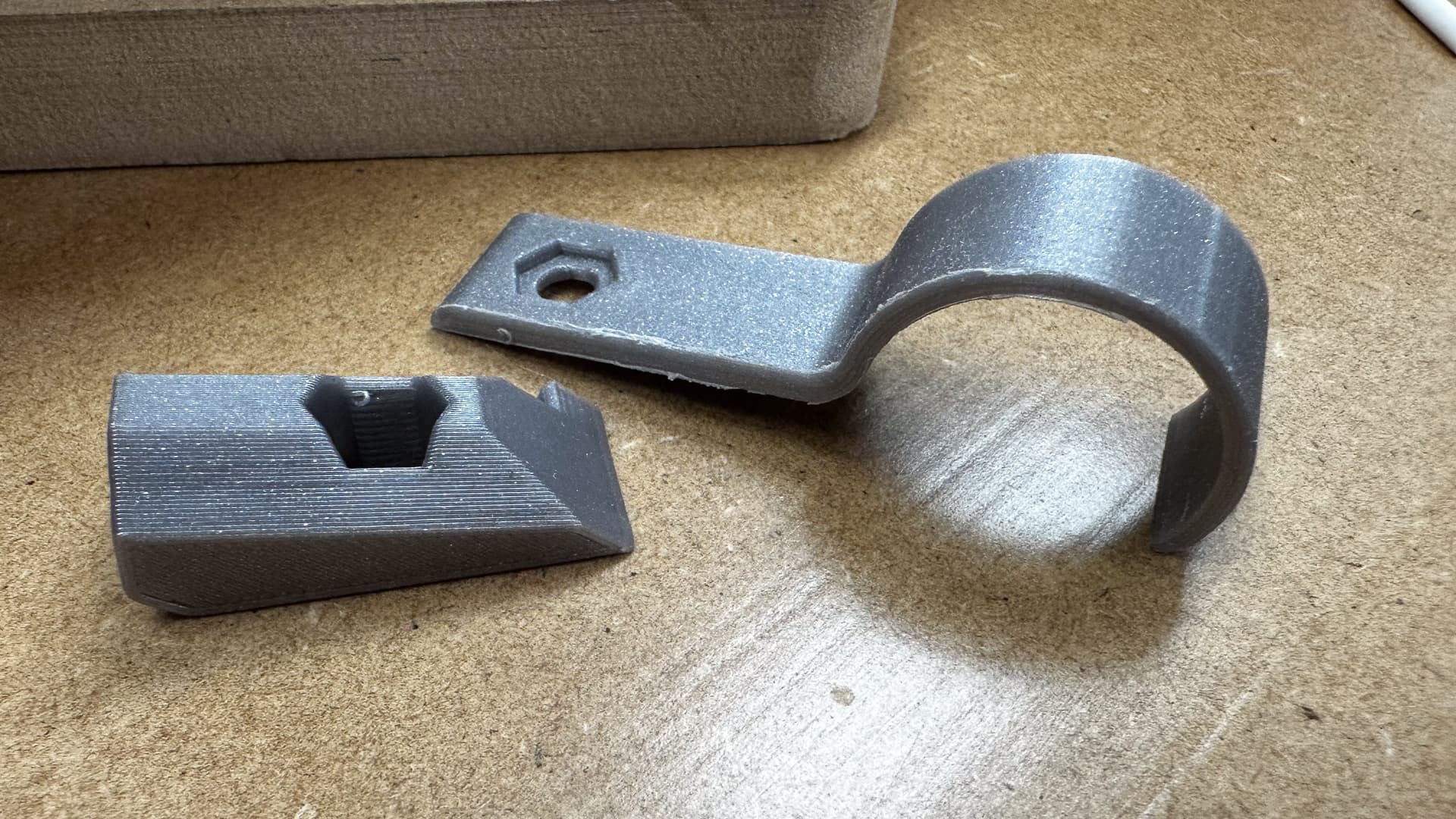
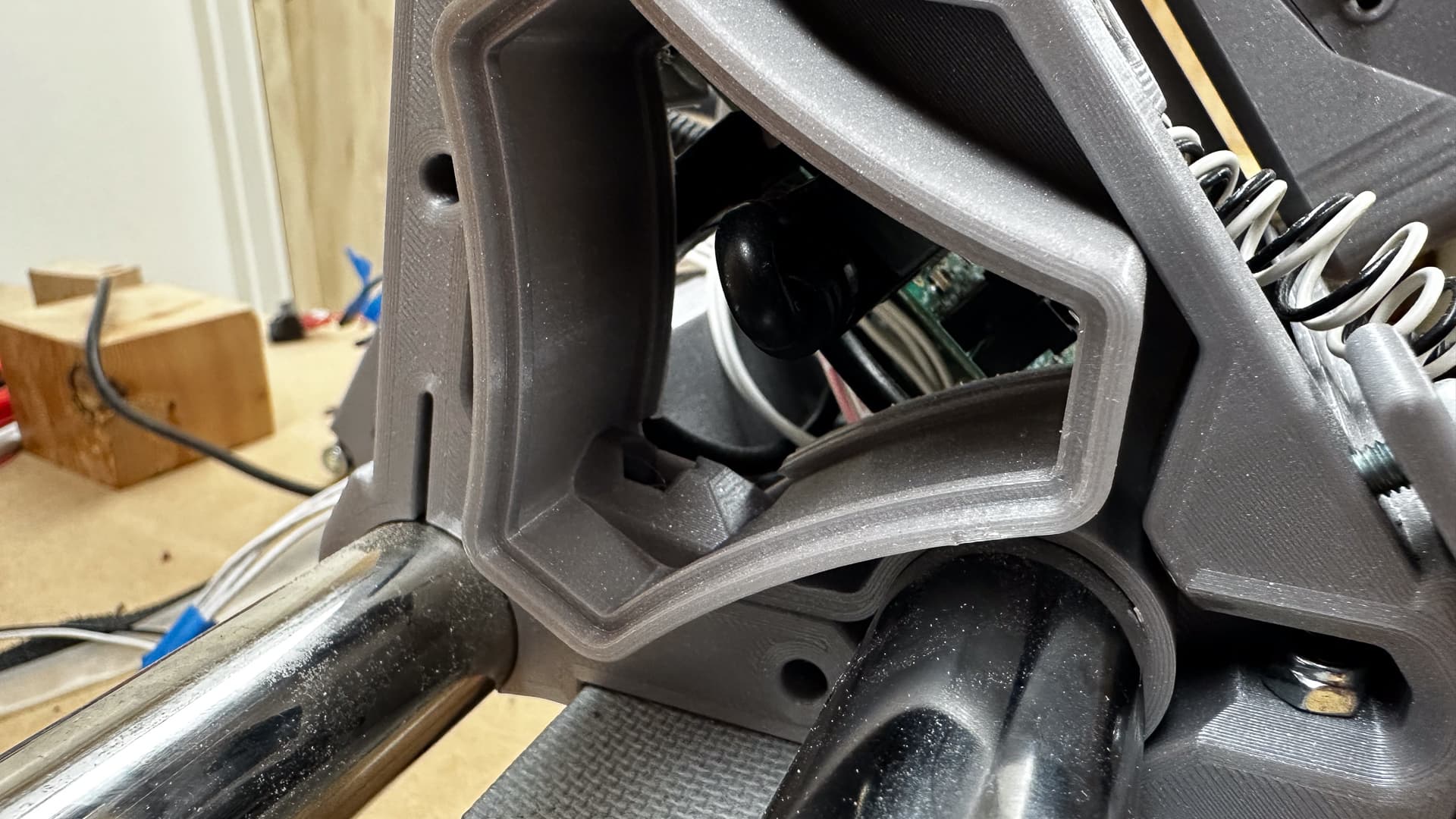
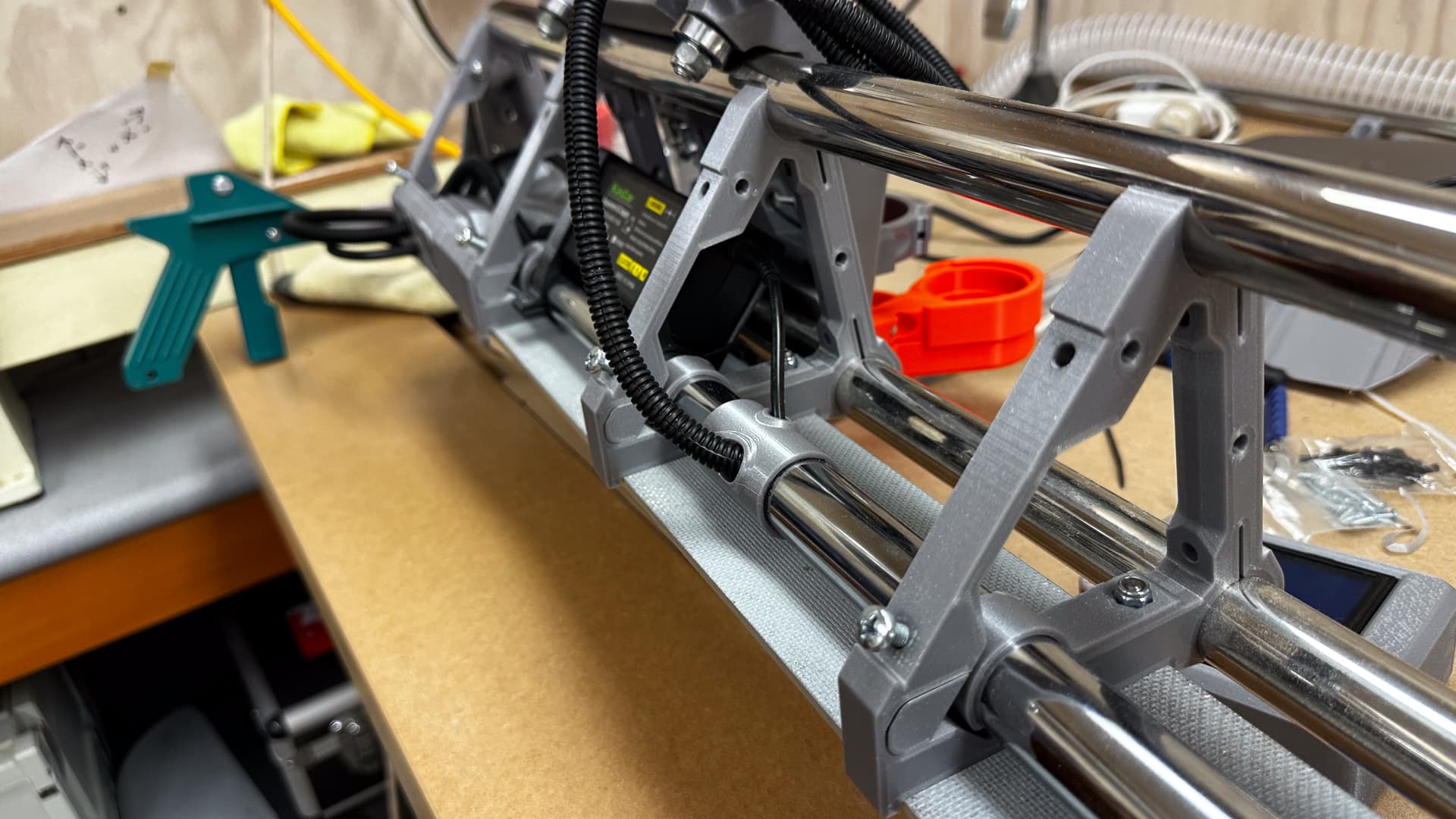
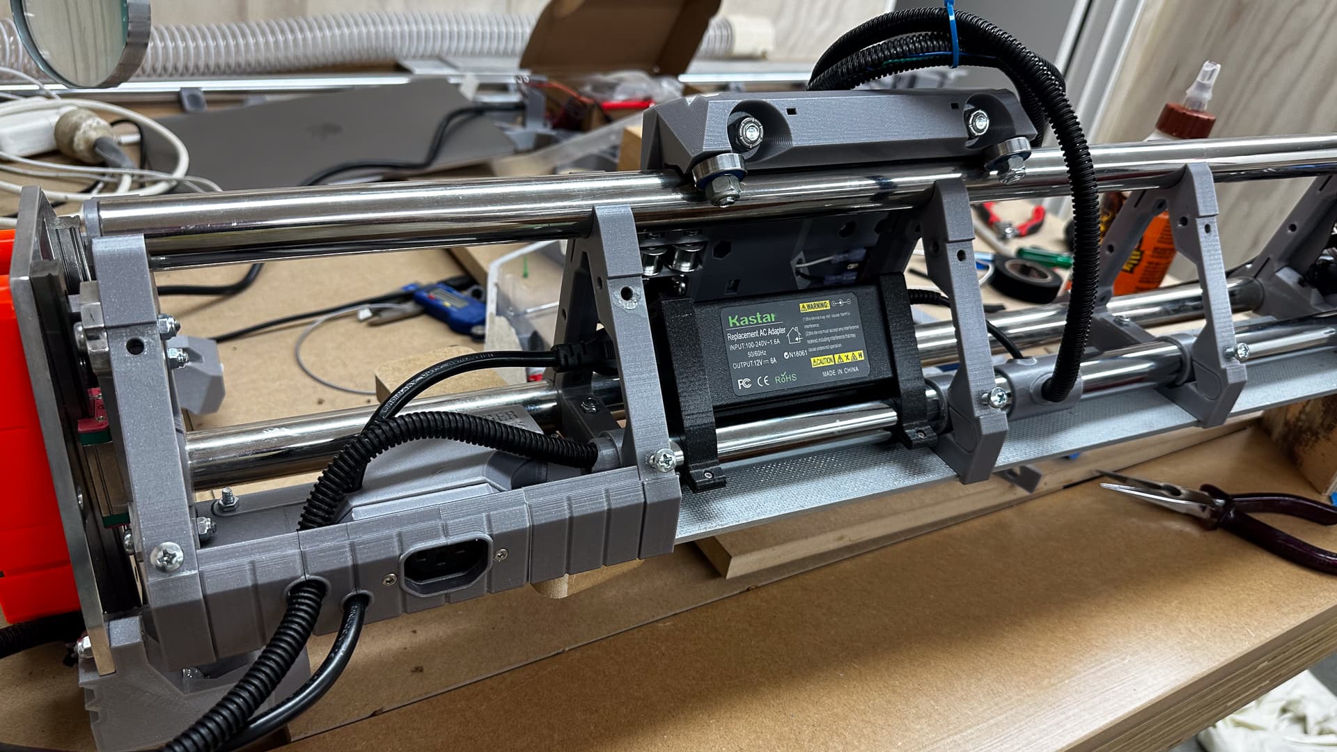
So I made some “encapsulators”, and while I was at it a clamp to hold my completely unnecessary but very shiny conduit in place.
Except that the two didn’t talk to each other so I had to combine them into yet another bespoke part which looks completely at one with the structure.
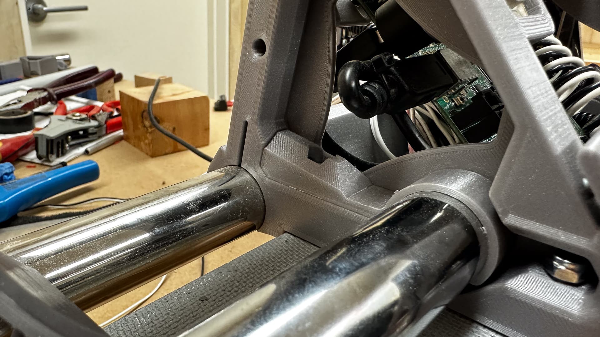
Except that they encroached on that little vent hole extension, but in the end it all fits like a glove, albeit one designed by a madman. Perhaps I could have made that vent a little smaller, but I’m hoping not to need a fan. No, the V1 logo wasn’t really an accident - it’s a very purposeful way of avoiding the conduit!
That’s yesterday’s roundup complete. It’s 5:00 am and I think I might even get some more assembly done today!
6 Likes
I want that on everything that I design. ![]()
5 Likes
I’m adding a heap of photos today which are going to seem like repeats to some, but it was quite a long day with not much to show but a lot of progress and I know how I like to pore over the finer detail in other people’s projects so either enjoy or ignore them!
Thanks for fixing the photo issue @vicious1 (and the browser version is working well too).
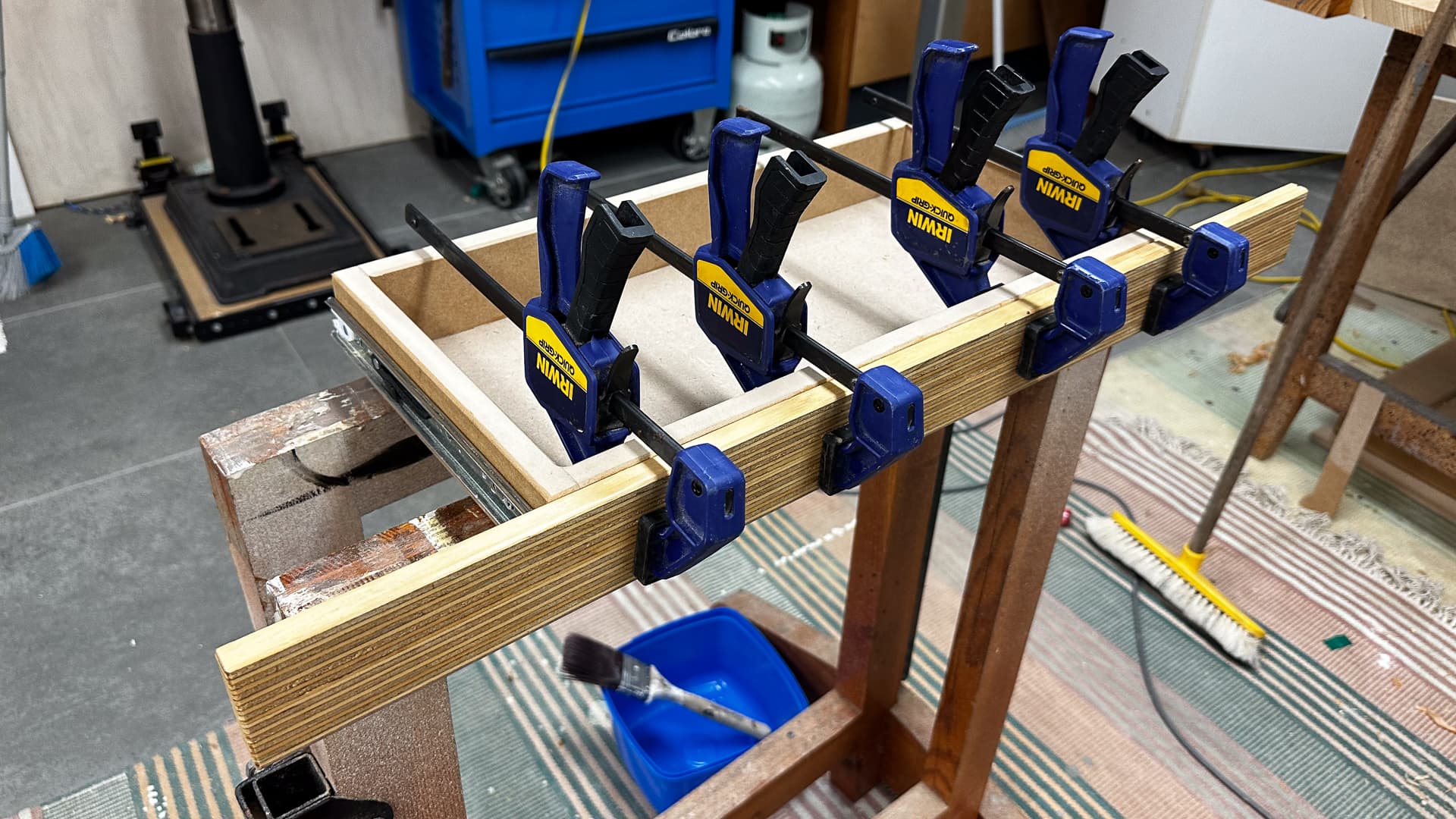
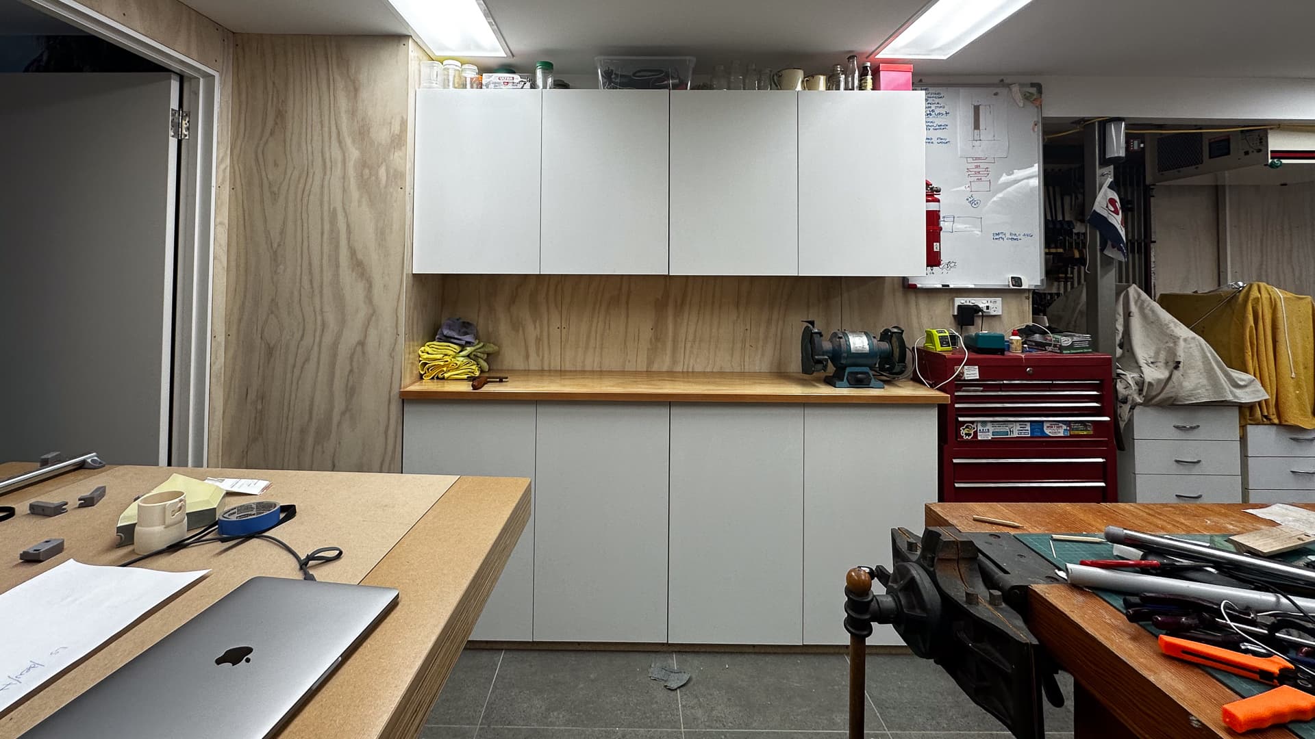
A bit of cabinet work to begin.
I rebuilt the drawer for the table - the first one was strangely out of square and it just seemed easier than trying to repair it. Glued the face on and it I’ll do the final adjustments tomorrow.
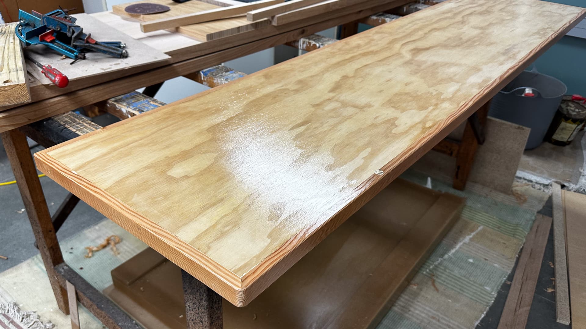
In the meantime, I’ve finished the benchtop for the other cupboard, got the doors on the tool one, and still have to empty the paint one to level it a little better before fitting the top.
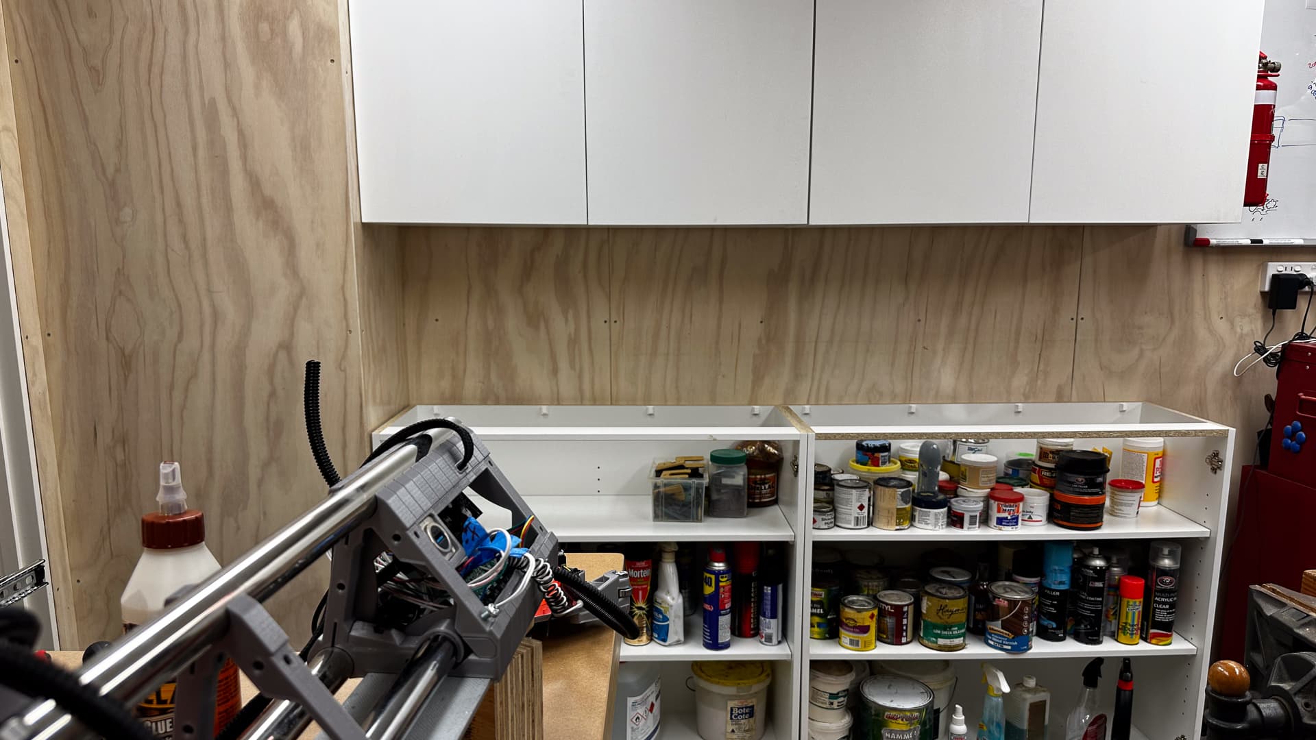
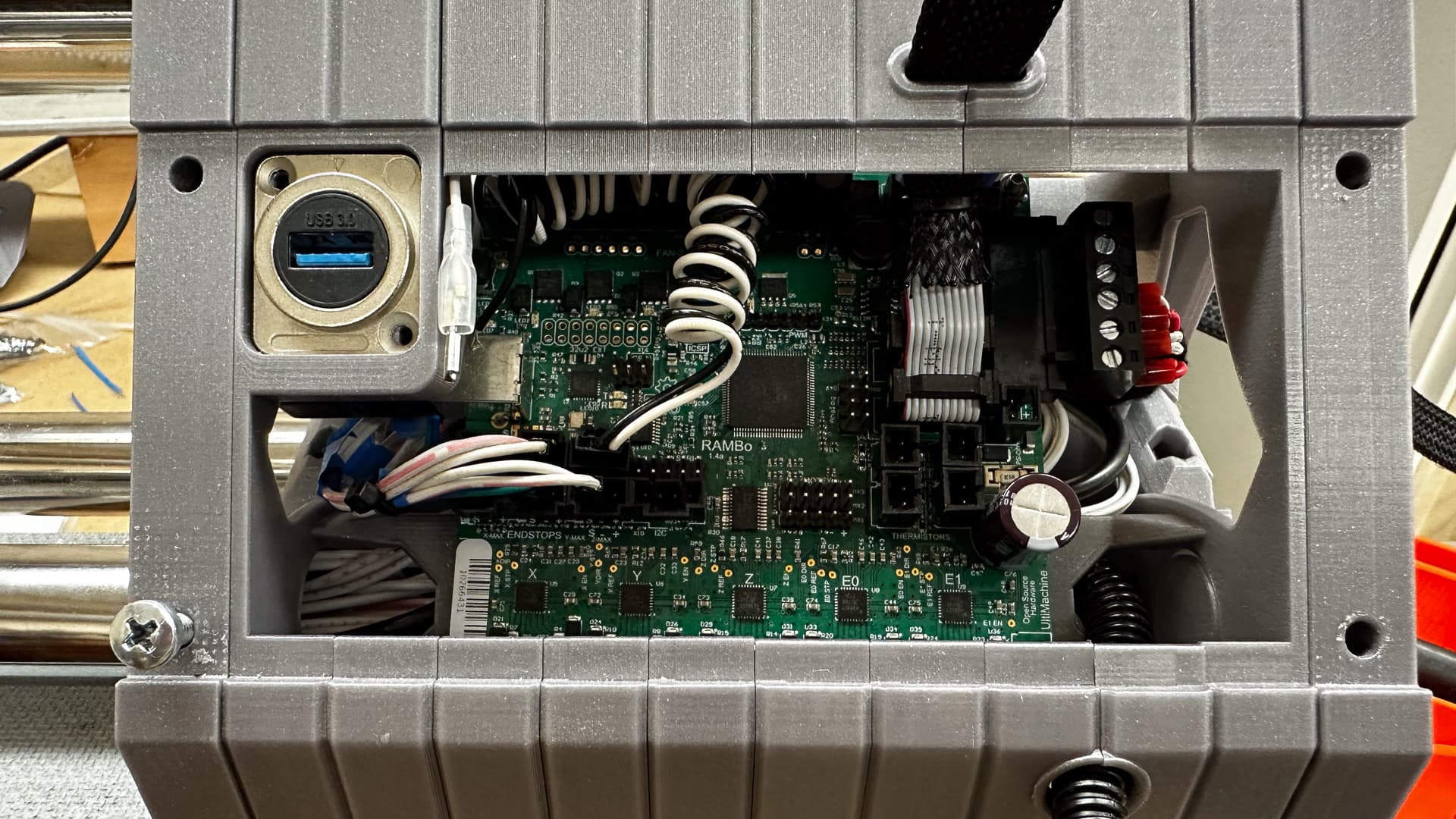
While all that was going on the final assembly is now in an advanced state. Everything is fettled, squared as far as can be at this stage and all the little finishing details are in place and at least the 240volt end of town is ready for the temporary struts. I probably don’t have to say that am very pleased with how clean and simple it all looks in real life.
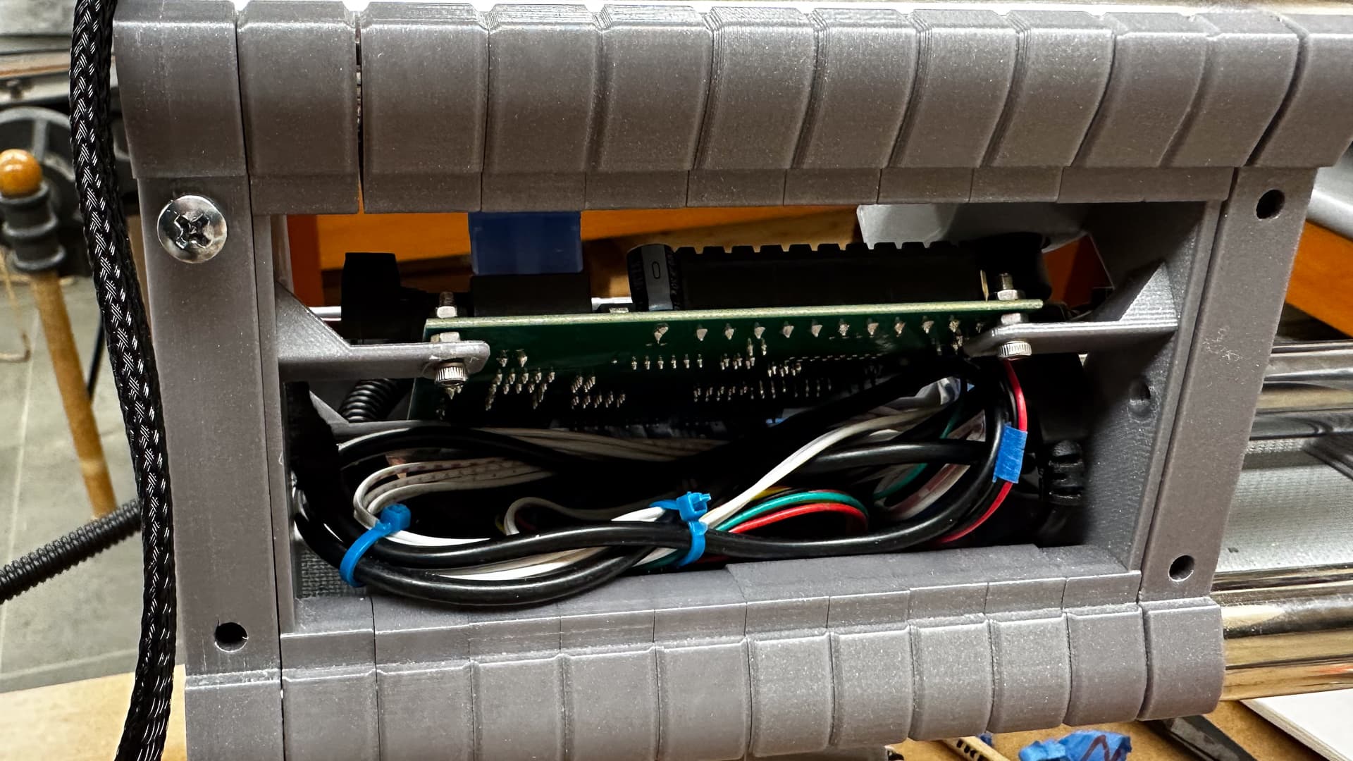
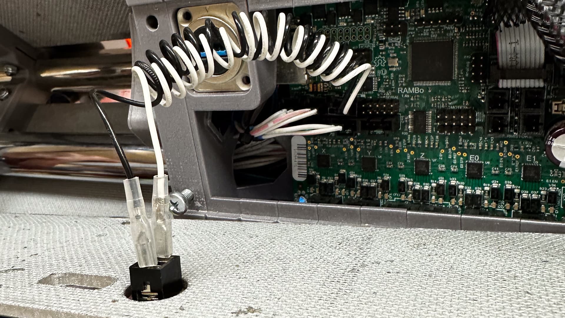
Meanwhile at the other end of town, making those connections in spaces far too small for an xxl sized set of hands required patience by the bucketload, and I am still to tidy them up!
I fired up everything using “table power” and all the steppers are working and travelling in the correct direction. Tomorrow I’ll double check, because I really don’t want to have to undo it all just to flip a connection, and then test the ends stops and the USB connections.
Then after a little bit of tucking and poking of stray wires, we should be ready for belts and a piece of track!
The curly wires are for the touch plate plug which initially will be mounted in the strut. I’ve run a spare pair to the core in case that doesn’t work out for me, and have thoughts of adding a plug on top of the core but at this stage, I just want to get on with it!
I’d say with just a bit of buttoning up and testing, we might even get a crown out of this baby in the coming week!!
6 Likes
I’m not sure why I haven’t found this morning stressful. It’s taken a very long time to plug in ten or so plugs and tidy up the associated wiring.
I suspect there’s a time bomb looming on some of those early crimps, but for now everything except the touch plate and USB connection have been tested, so we might bolt on some struts later in the day.
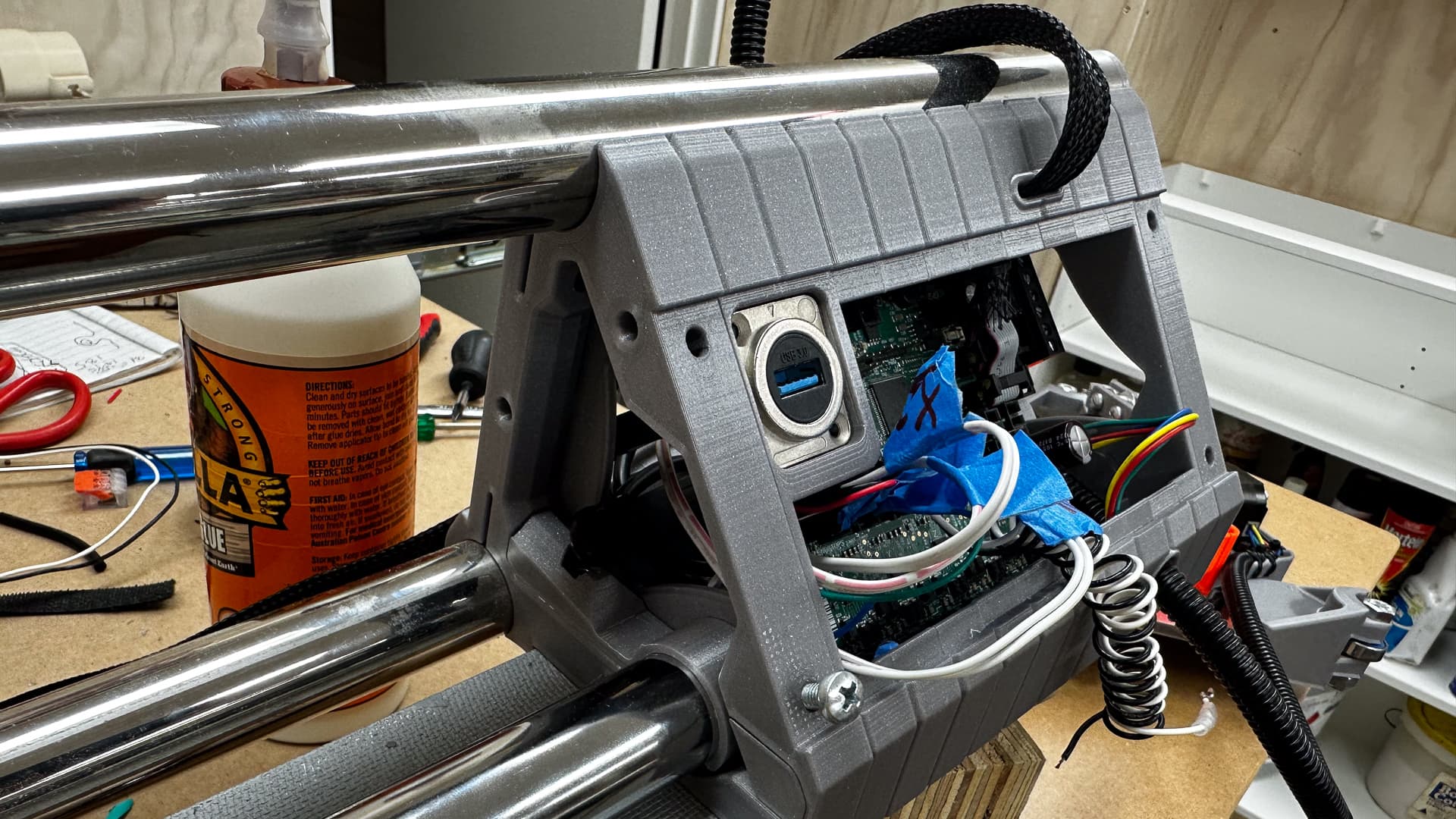
The USB connection of course now has the pass-through in the middle of it, just one more thing to go wrong, so wish me luck.
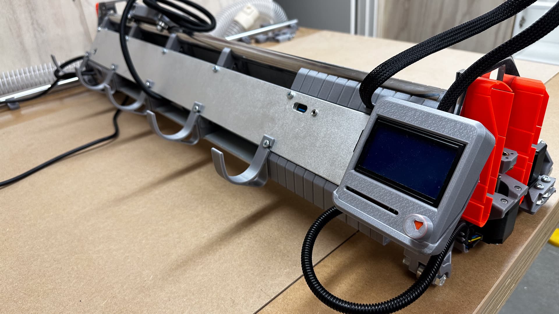
It’s bolted in and satisfyingly tidy.
7 Likes
Well I might be slow, but at least I’m expensive!
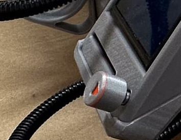
Here’s the back of the touch plate plug ready for the strut to be mounted.
…and with the strut in place, it’s the little dot this side of the USB port.
The final iteration of the strut is planned to be in mirror finish either ACM or aluminium, with a simplified strut, and I have to say it’s hanging out for a window into the board - do I print one or make it properly clear? It will need a blue light of course to match the controller.
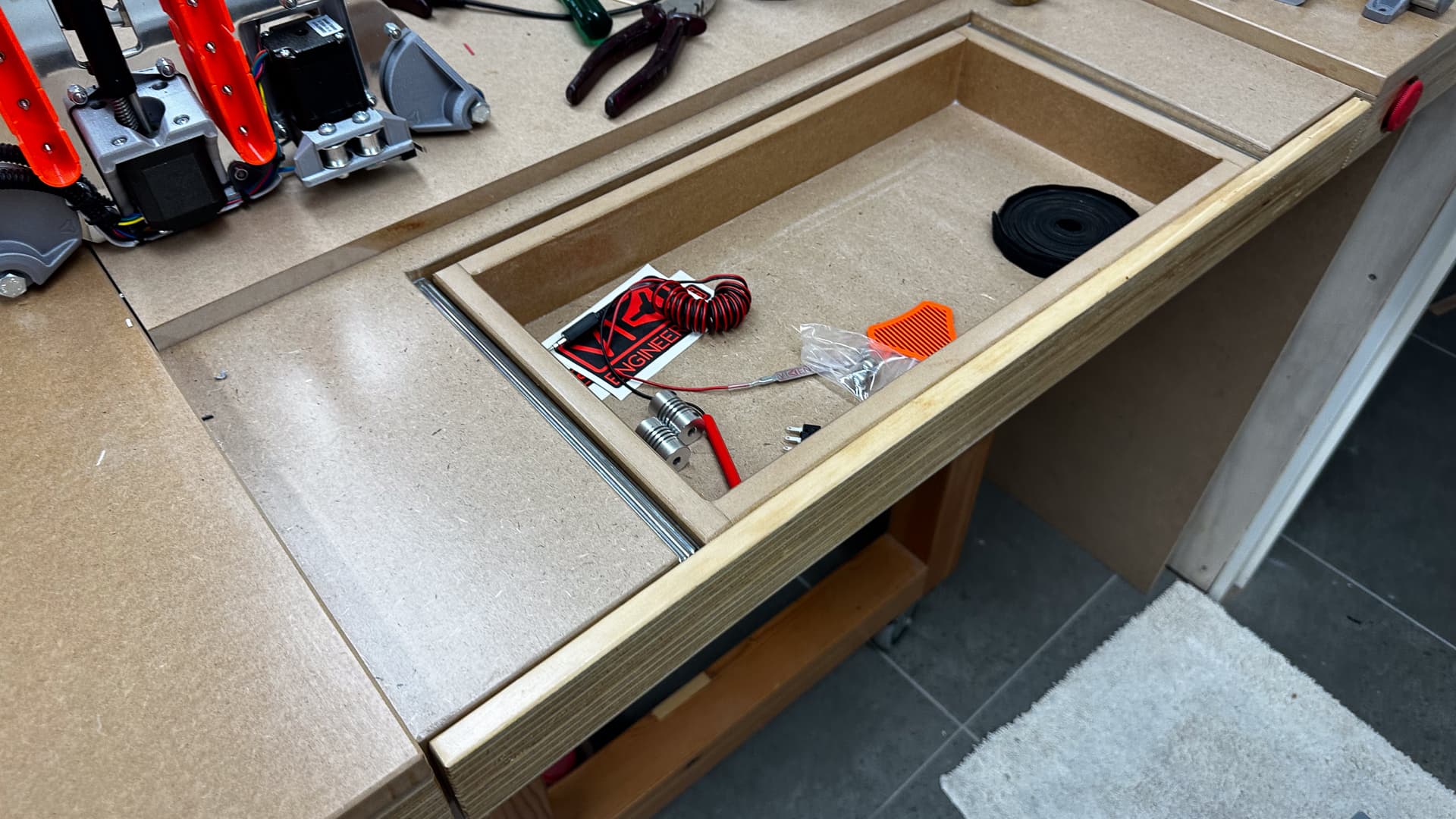
I wouldn’t consider fitting drawers as part of my core skill set, but this one works well, (with the spoil board pulled back so you can see it). In a way this is similar to @vicious1 's setup - if you check out a post a hundred or so up, you’ll find a sketch of a cutout to allow vertical mounting of stuff - it occurred to me during construction that the back of the drawer cutout is just that and it’s 500 mm wide If necessary I can even make an adjustable table below it, running off the legs.
It looks as though we are getting somewhere now.
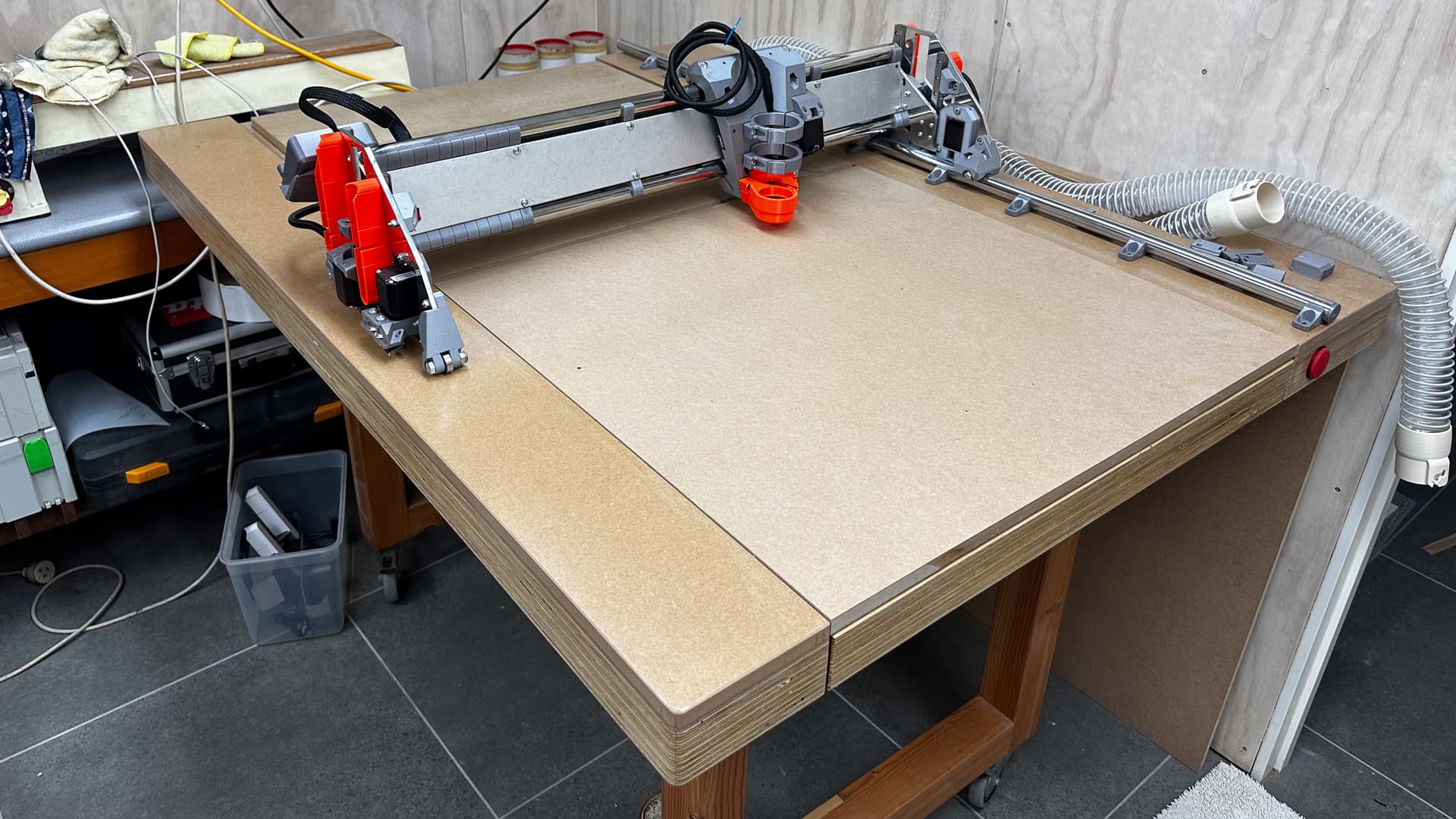
All that orange will disappear shortly, but for now let’s get this thing moving! I’ve had no luck with Repetier though, sometimes software hides obvious things.
INORDINATE : - the amount of time I’ve spent on this project dealing with tiny unnecessary details, just for the sake of it.
6 Likes
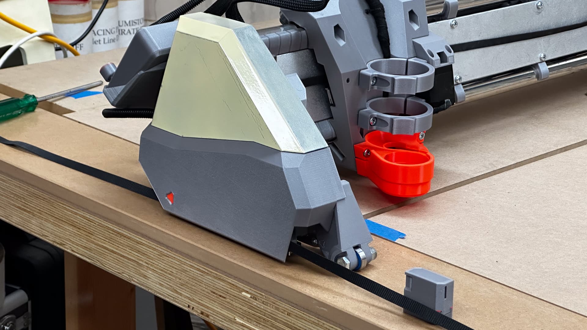
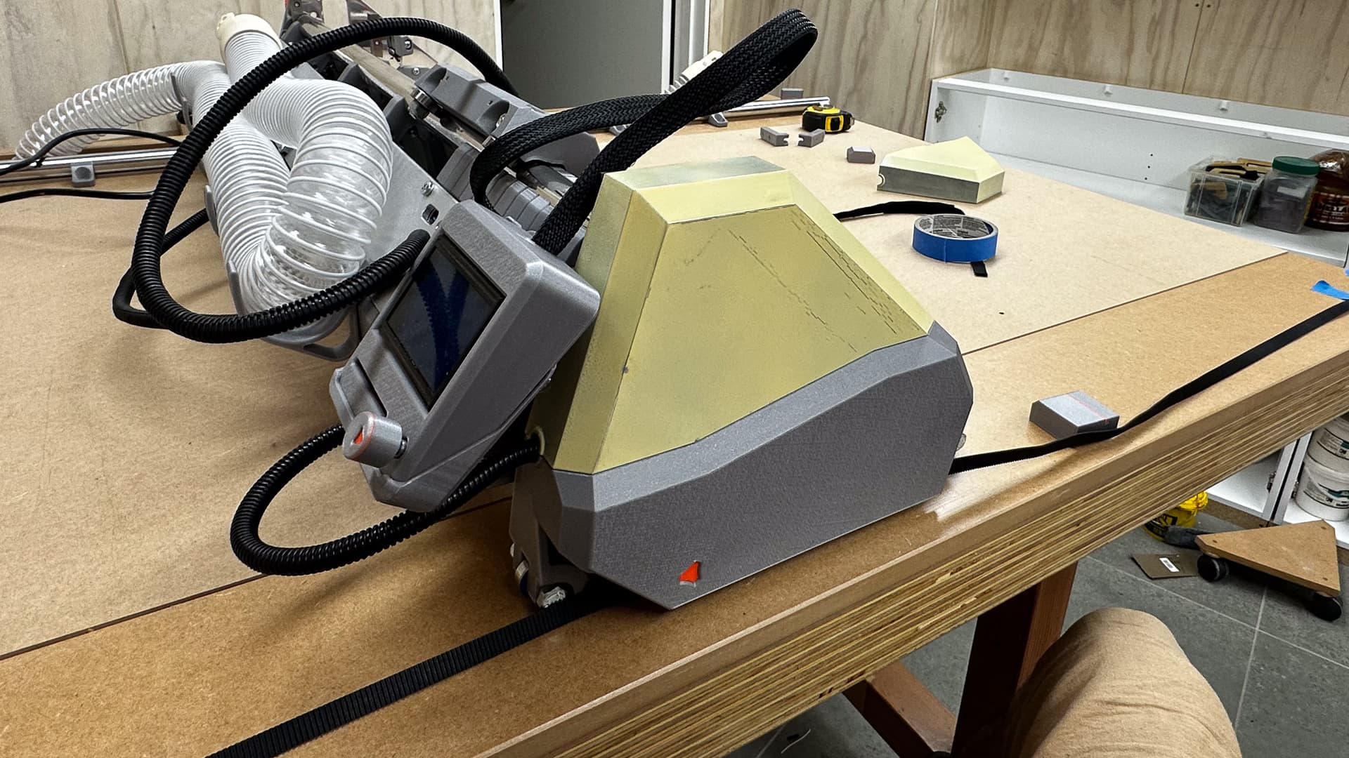
In case any of you were wondering about the outcome of those painted covers, let’s just say they were a complete disaster. I gave 'em a quick squirt of random cream today just to cover up the biggest part of the mess, but that didn’t work.
I will be reprinting them in a vanilla colour, but I think after the impact of the orange and white, nothing will compare!
They do fit beautifully - I just have to make sure that they don’t foul on the stop-blocks before I share the files.
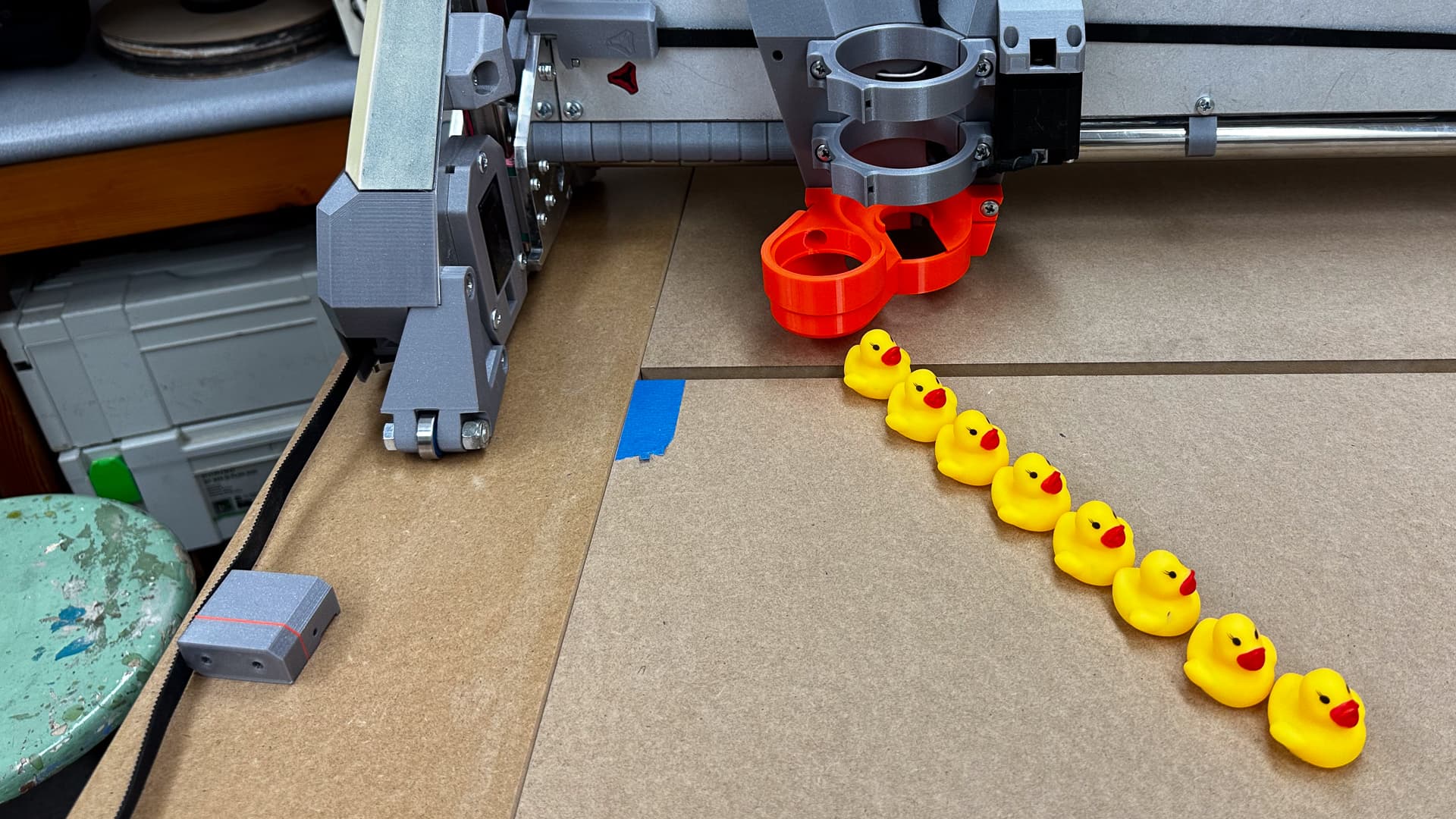
After today I’m going to call that eight ducks in a row - or about half way I reckon!
- Perhaps tomorrow we’ll have a crown, but after that the list of things to do to complete is lengthy and will take time. In no particular order:-
- Fit and finish the spoil boards
- Commission the machine and square it
- After testing the vac hose - make a suitable vac shoe.
- Test the router for plumb and decide whether a cam-adjuster is in the future
- Muck around with some alternative struts.
- Make the struts and fit.
- Decide whether vanilla and grey is really the colour of the future or do we return to white and orange?
- Set up a separated vacuum/dust collection as per the sketch waaaay above and make a sound proof enclosure for it!
Put that in the mix with a month of travel between now and December, and of course the imminent arrival of the Mk$ kit and you can rest assured this thread will not be closing any time soon!
6 Likes
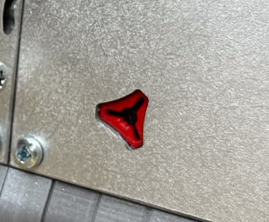
Be still my beating heart…
6 Likes
Am I the only one thinking this build really needs a V1 logo-shaped key as an on/off switch? ![]()
4 Likes
With a laser I could engrave the e-stop switch! ![]()
3 Likes
I haven’t exactly been doing nothing for the last couple of days, but progress has been less than stellar while I failed to sort out Repetier. Not to worry, I’m pretty confident with the controller and since I’ve now checked out the touch plate works, there’s nothing holding me back.
Not the cupboards, which are now waiting on the LR3 so they can have some handles.
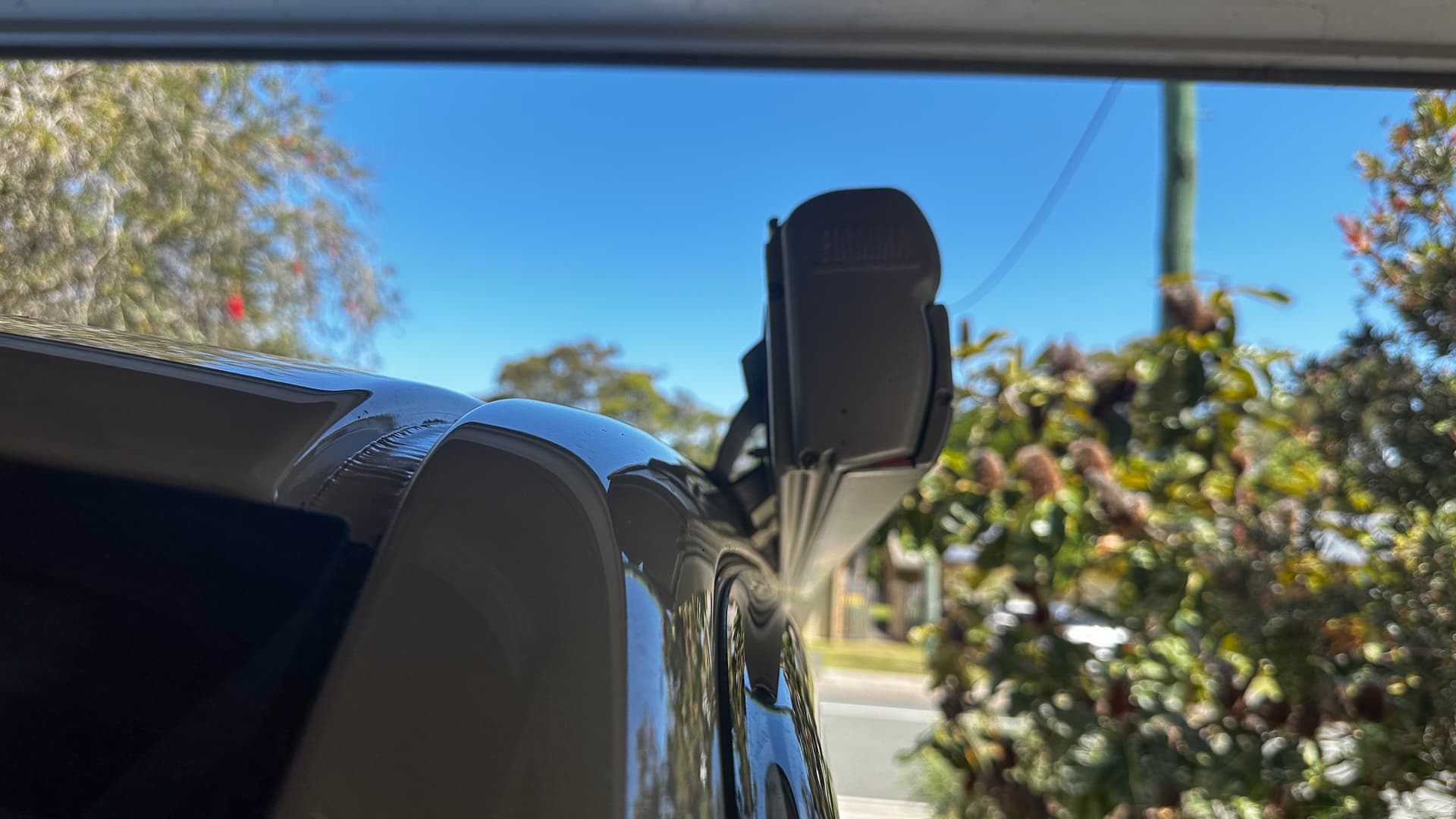
Not the flashing between the awning and the roof on the camper, which as of this morning is glued happily in place.
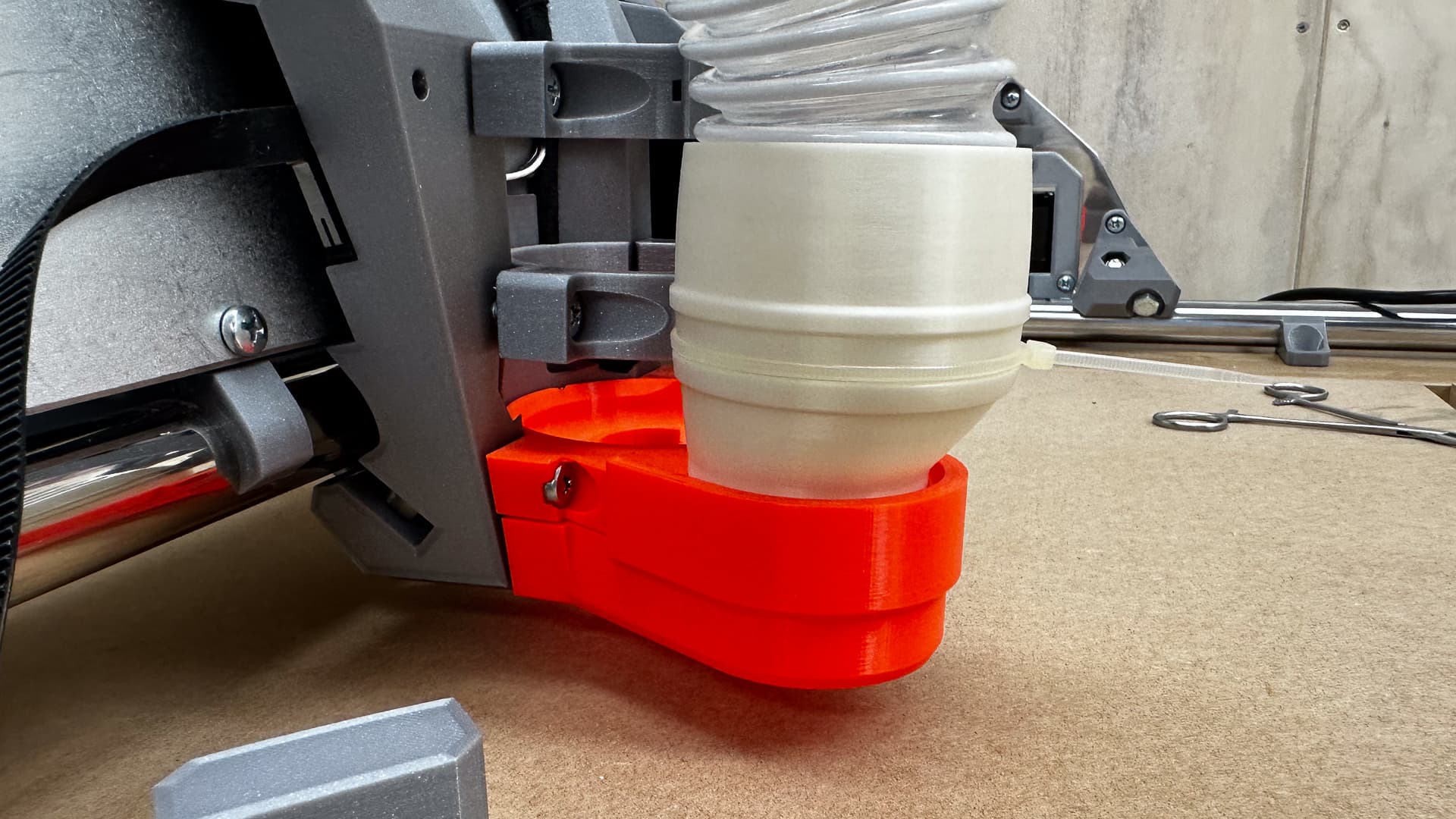
Not the need to make a vac adapter for the 2" hose to do me until the revised versions get done. (I quite like the two little ribs to stop the zip ties slipping off).
Onward and upward - tomorrow- the crown!!
7 Likes
FINE THIS IS HOW IT’S GOING TO BE!!! - so end stops, says the document, require intermediate skills to set up and clearly a little knowledge does not add up to “intermediate”.
Looks like I’ll be ignoring them for a while then!
While bench testing everything worked as expected, but I put a belt on X this evening and when I moved in a + and - direction all went according to plan.
My bench testing involved hitting the “Home X” menu, the stepper spun happily until I hit the end stop and I just thought all was fine. Tonight, when I hit the very same menu the core jogs about 10mm in the “+” direction, which I am fairly sure is the wrong way, and then stops.
Wherever it stops becomes X0.000
I therefore assume the V1 Custom Menu “Home X & Y” command will do what I am expecting.
Is it time to read the instructions?
1 Like
Be honest, you’ve already read them twice anyway. ![]()
1 Like
That means it thinks the endstop is triggered and is trying to move away from it. Did it come unplugged?
3 Likes
The endstops are not that hard, and they are worth it. We are here to help!
1 Like
Seems like your endstop is wired NC instead of NO, or the other way around
On a side note, I find fluidnc, klipper, or rrf a lot easier to setup
Jackpot controller is a great upgrade, even better than the “premium” rambo option for this very reason
Being able to just use a web interface and config file really helps in testing and understanding what you really do…
Arduino compilation and stuff just adds an unintelligible and useless layer to the whole process, meaning you spend more time fighting with the shear work of configuring your machine rather than actually configuring and testing it
1 Like
This sounds like a disconnected switch.
End stops 101 (Electronics for English Majors.)
The processor on the board can look for, or set one of two states on a pin. Logic high is when the voltage measured is greater than a set point (call it 2V, but it varies a bit – hence the issues we have been seeing on the SKR Pro boards.) Logic low is when the voltage js below that point. Everything about the end stops starts here.
On the board, there is a resistor between a voltage source high enough to set logic high and a signal pin. With no other route to ground the effective voltage at the pin becomes the same as the source. Therefore the default state of the signal pin is logic high. V1 firmware treats this as a triggered state. (The light switch is “on”.) An analogy with a water hose is turning the tap on, but only a tiny way into a plugged hose. The water pressure will build up in the hose to the same as the water line before the tap.
The resistor is used because we have the switch wired as “normally closed.” This is counter-intuitive because this is the state that we think of as “on” with a light switch, but because of the way we have it wired, it is reversed. While the switch is closed (passing electricity) it is instead allowing the power to drain from the voltage source, through the resistor, to the switch, and then to ground. This drops the voltage on the pin to near ground level, or logic low. This is then registered as “open” by the firmware. The water hose analogy here is that we unplug the hose, and the water pressure lowers to near nothing because we are letting it flow freely out of the unplugged end.
(Note that using the word “open” here is misleading, because the switch is closed. When the switch is open, the pin is “triggered.” I wish the Marlin dev team had made proper use of a thesaurus here…)
When the switch lever is pressed, it is the same (or close enough) as unplugging the switch. The voltage has nowhere to go again, so it builds up, and the pin goes back to logic high, and the firmware reads that as “triggered”.
We want the switches wired as NC. Or at least that is how the firmware is comfigured.
I have said this before, but I think the philosophy of using NC switches as a safety feature isn’t quite right.
The idea is supposed to be that if the switch becomes unplugged or the wire is damaged then the firmware will see it as triggered and not move the motor. This is fine on a single motor or a single driver, because it means that the motor won’t crash the end of travel. In the case of a 2 motor system (say LowRider Y axis) it might pull the machine very much askew if only one motor moves. This could potentially damage the machine, whereas trying to move past the physical stop has a very low probability of doing much damage.
Therefore it may actually be safer for our machines to use normally open wiring (the way the touch plates are configured) instead.
A downside for boards that have an LED for the stop is that the LED will be on, and.go off when the stop is triggered, but that’s how the touch plate is already, and that isn’t a problem…
3 Likes
Thank you to you all!
At this stage of my learning curve I am still overlooking the obvious - this is a “lightbulb” question! Remember my dodgy crimps? It’s a very likely scenario, on that basis I think I am going to treat this as a temporary problem and go tracking it when I have the new braces cut. (The reality is that it will bug me and at 1:00am tomorrow I might get out of bed and do something about it.)
That’s exactly why I love you all!! ![]()
It’s wired correctly - Dan’s explanation clarifies this, (and it did work during testing).
As soon as Ryan suggested it above I have to agree.
Thank you so much for you detailed explanation. I hope it’s not just because you wrote so clearly that I understood every bit of it, and that it’s a sign that I really am on the cusp of actually understanding stuff here! I just need to apply that simple background logic to the fault when problem solving.
Curiously, the NO/NC stuff makes perfect sense to me until you explained that it doesn’t!! I simply imagine the symbol for “switch” as “open” and a wire as closed.
2 Likes