I am not sure how the PLA will survive so close to the steppers, but I suspect it will be OK, summer temperatures in my workshop hover in the early 30’s mostly - I think with the bottom completely open and the aluminium plate acting as a bit of a heatsink (maybe?) it should be OK. I will of course report here if it’s not!
2 Likes
After the excitement of the last few days it’s time to get back into more mundane stuff and brace myself for the let down that building it in dull grey will no doubt be!
First job: - Drizzle a little epoxy into the captive nut socket. If any of it leaked down into the thread from below you might hear me from where ever you live in the world! Look at all those screws that need cutting off!
With really rough assembly complete, I’m happy to report we have clearance to burn - I’ll actually put some washers under all the brace bolts now just to give a tidier job against the paint.
Ready to build the wiring loom - after a big tidy up.
When I said that we were viewing the “fenders” in isolation - this is what I meant - if anything to quote @vicious1 , it’s getting better again - it really looks proportionally like part of the machine. I cannot lie, I have been really tempted to order another spool of orange filament, print a new core and paint the braces white. I can see some super colour schemes coming up if anyone else decides to use these “fenders”. Should I just start referring to them as “covers” because that’s what they are?
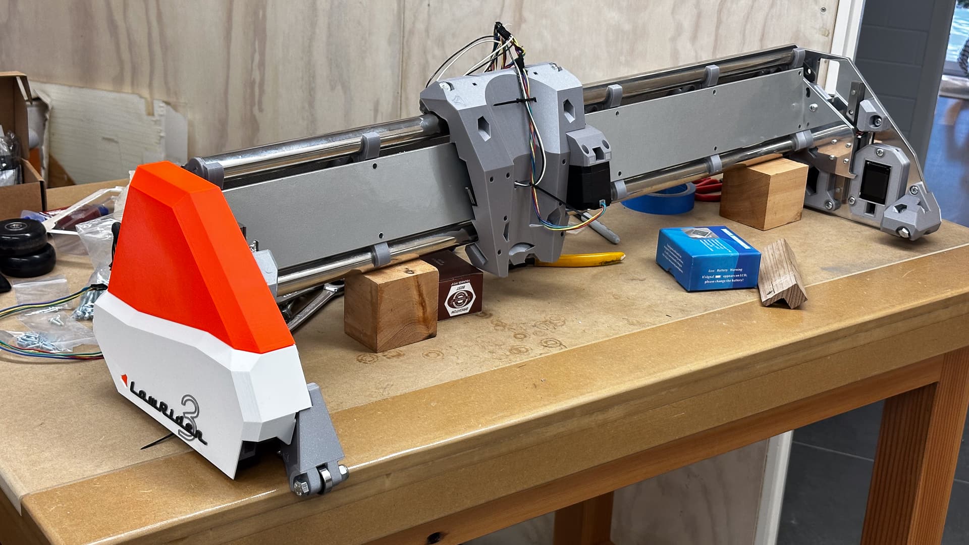
My original colour scheme was an ultra conservative grey on grey and I’m going to stick by my guns no matter how boring that is going to look compared to the white and orange version, and keep reminding myself that the white bits are already looking a little grubby.
All up though the machine is really starting to look more like a commercial product than a home built one, which is very satisfying.

6 Likes
They are quarter panels.
4 Likes
That still looks amazing all silver! I agree the white would look dingy in no time. I know it would for me anyways. I can get finger prints on stuff I don’t even touch LOL
2 Likes
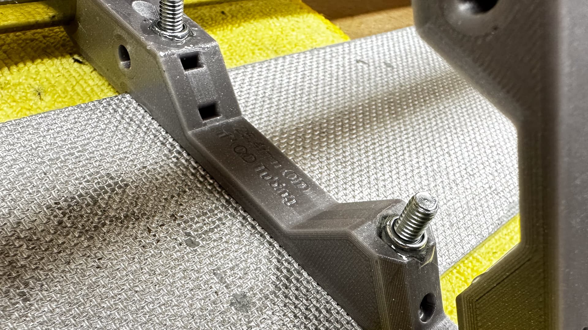
I can’t say I’ve ever noticed it being a problem, but with the aluminium plates there’s no easy way of securing wires, and the prospect of loose wires hanging from a moving object 6mm above a table top was not appealing.
So I made a little cable tray/skid plate and that made me almost as happy as the orange “quarter panels” do!
If you had noticed that I’d left two bolts 1.6mm longer than the rest when I was cutting them off yesterday, and were too polite to point them out, this is why:

7 Likes
I am pretty sure we all noticed, burying our head in our hands and shaking it silently in disapproval because of your shoddy work. ![]()
Joking aside: I really, really like the look. It’s incredible what you can do. I can only hope to be half as good as you when I am your age. ![]()
3 Likes
Well you are half way there (to my age I mean), so you’ve got a great chance of that! ![]()
![]()
(Thanks)
1 Like
Even without the covers on, this is, by itself, already a great mod I can see myself using
1 Like
Thank-you!
I’ll try to crank out an upload to Printables tomorrow - might not get there but probably will - I have to modify the stand-off height for different thickness plates, just to be sure to keep away from the belts. It’s a bit fiddly to bolt on but works really nicely I think.
2 Likes
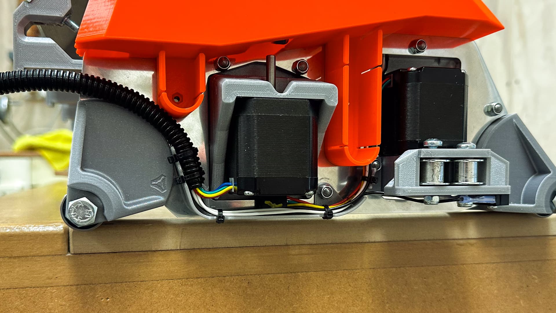
There is a cable tie slot in the Z stepper holder. Your clip is just about covering it though.
2 Likes
I think this won’t be compatible with my setup though
I’m homing in the Y+ direction, so the endstop block has to clear the bottom of the Z motor
But for a more standard build, that’s a great solution
Yes, I should have been clearer - the wires run on the wrong side of the clip (even if the slots were accessible) - but the one on the Y holder is still available for use.
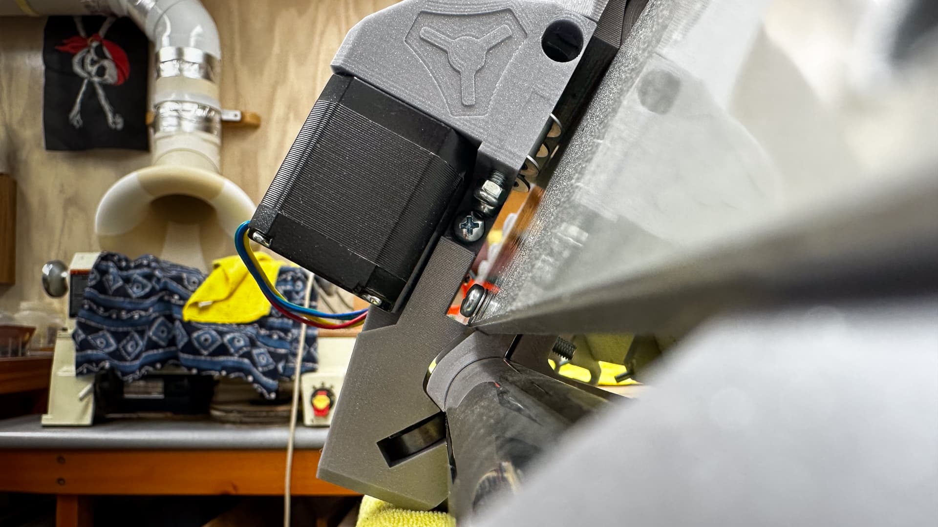
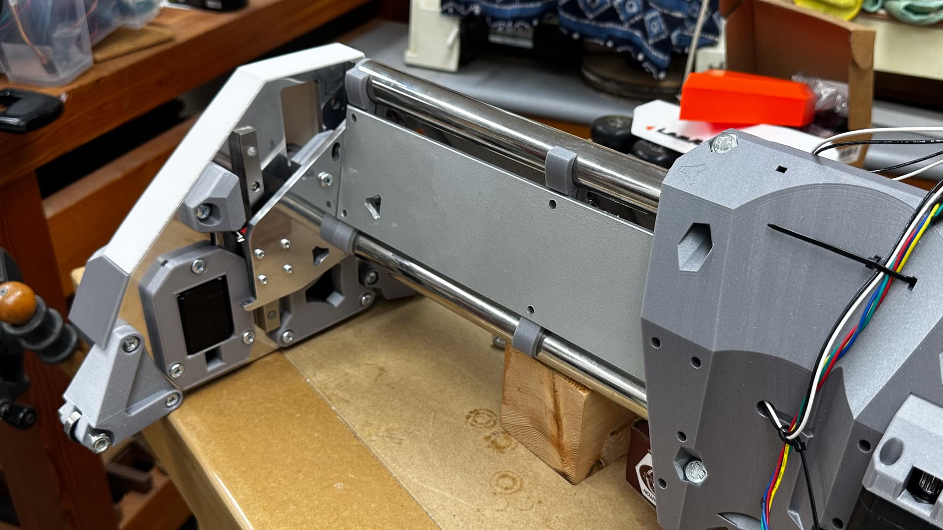
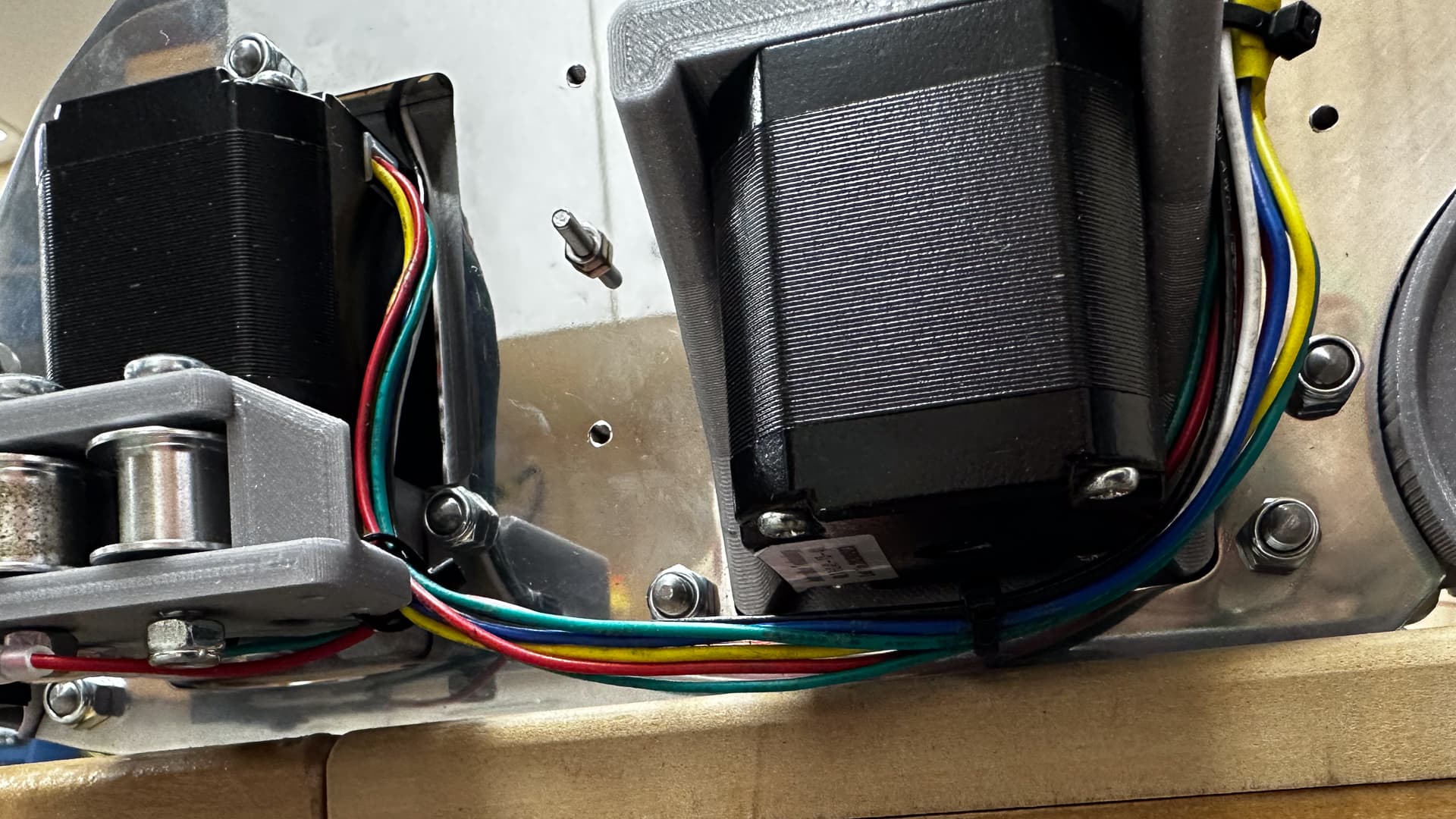
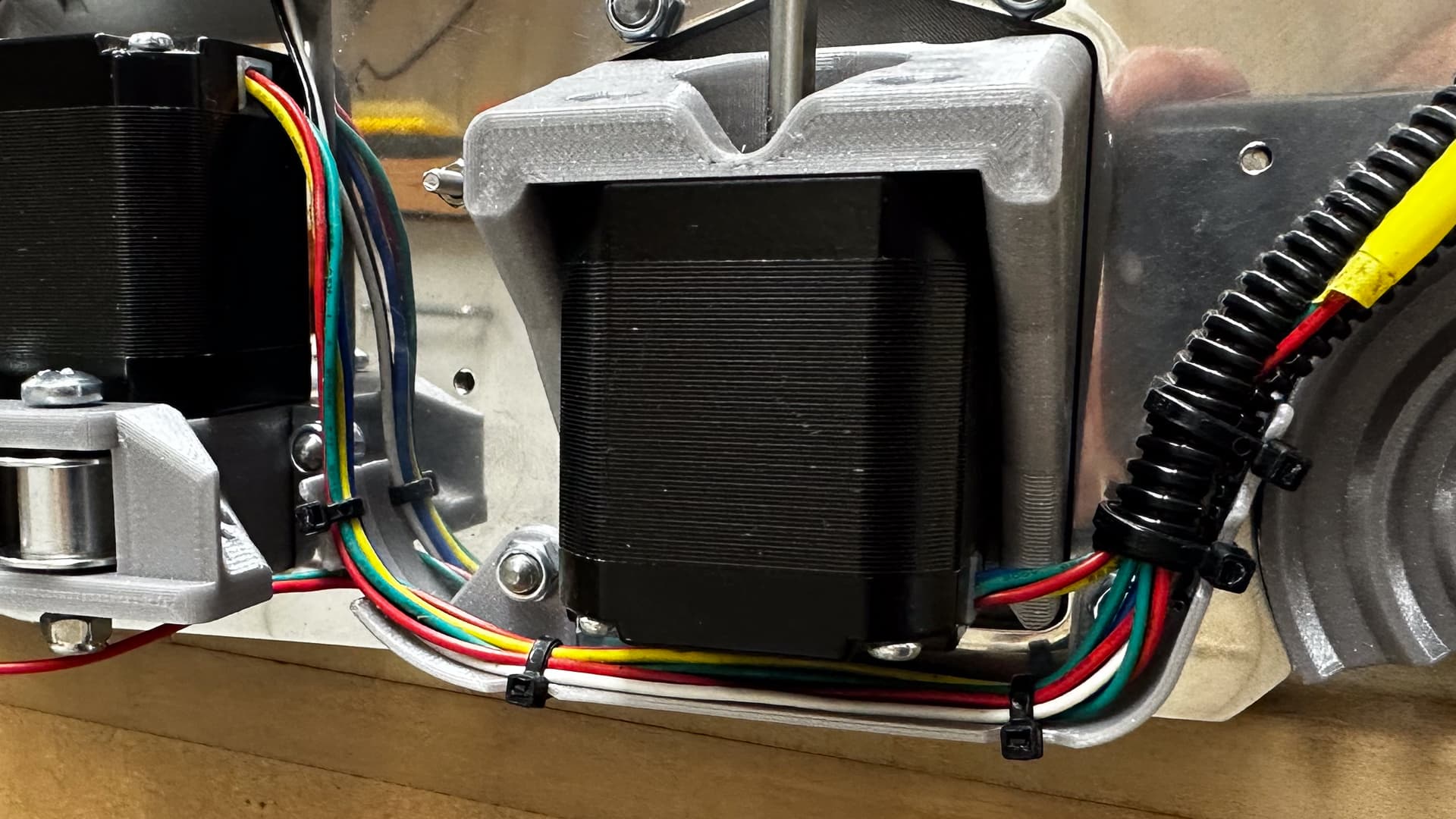
I have a couple of other non-issues that the “cable tray” sorts as well, the biggest of which is the length of the Y stepper cables, so neatly cut and re-pinned to fit perfectly on the LR2. The connectors are in exactly the most awful spot - under the Z stepper!
This mount stops any risk of sag, and keeps the wiring off the steppers at the same time, but even more importantly there are no pesky stray wires to catch between the fancy covers and the plate and the cable now has no need for any strain relief.
I was going to solve all of those “first world issues” with loom tape, but this is nicer.
3 Likes
This is why you don’t document your build in a super public way kiddies!
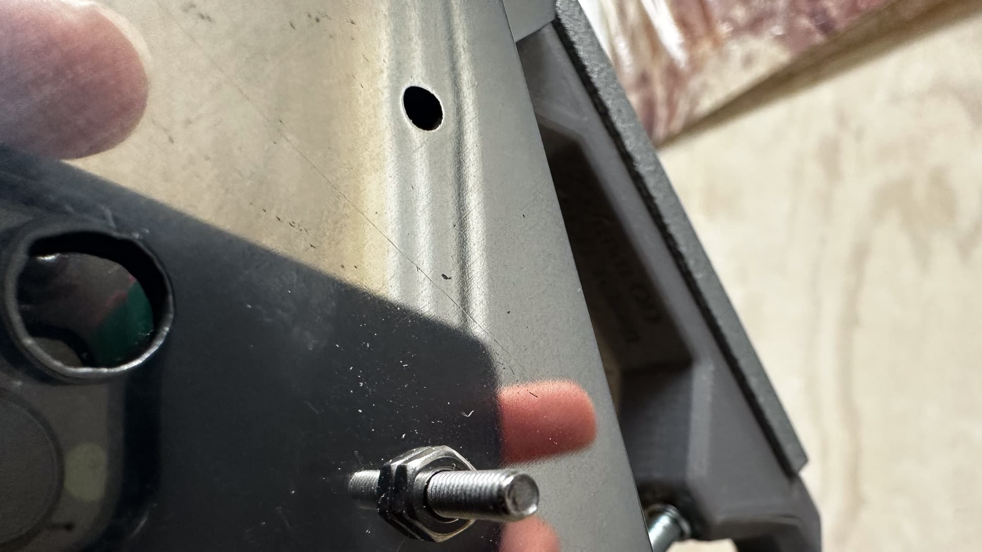
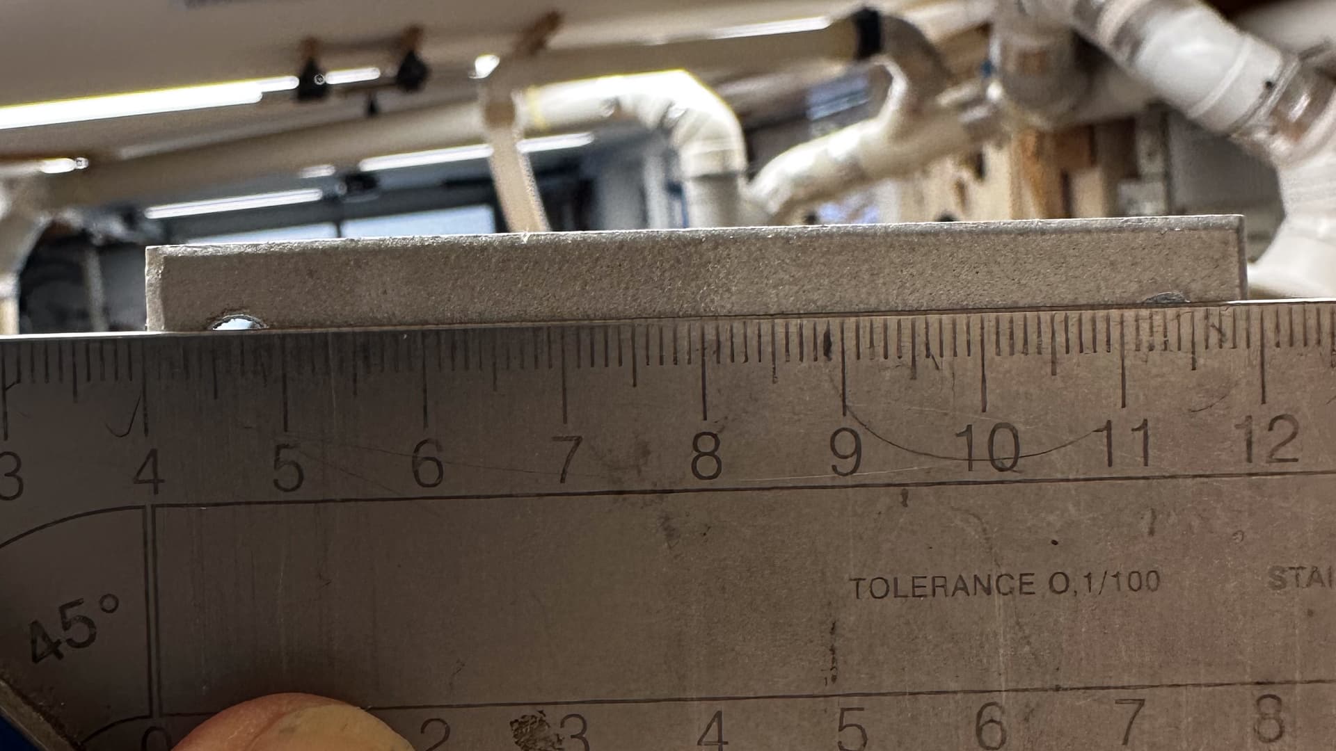
Turns out that my “temporary” struts so carefully made by my own hands have one hole slightly mis-positioned. It’s somewhere between half and one millimetre out.
Naturally it’s a corner one that’s fairly important to ensure proper alignment of everything, and this error presently translates to more than 6mm worth of “toe out”. (with no proper adjustment)
Since I drilled the first row of holes and used that as a template for the other, that would have meant three problem children, but of course I flipped it over and drilled two more meaning the opposite diagonals are out, and then used one of those for the original brace - so by my maths I have six of the twelve end holes misaligned.
It’s just as well I have a bigger drill bit. I’m sure it will be fine and the oversized holes won’t affect anything, but I’m taking the parenthesis from “temporary” when I talk about the struts from now on!
2 Likes
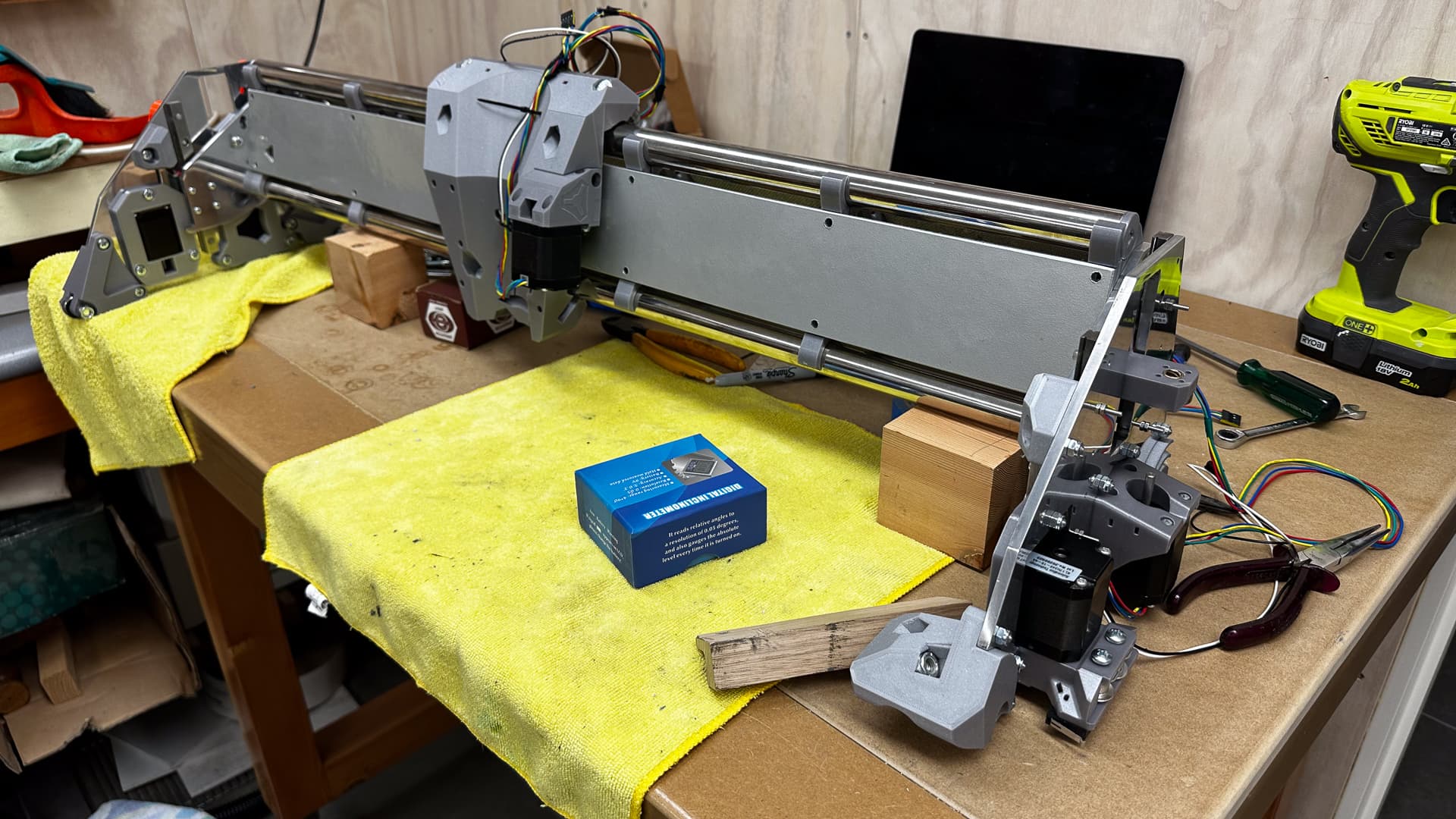
Now seriously out of my comfort zone (and very close to the edge of my understanding one too), I’ve started to untangle the wires rescued from the LR2, and it has suddenly dawned that with endstops I am now way out of my depth!
If the answers to my questions are in the documents I am more than happy to pointed to them! For now, I am starting at base zero with my existing Rambo board and need a bit of confirmation/handholding so here goes:
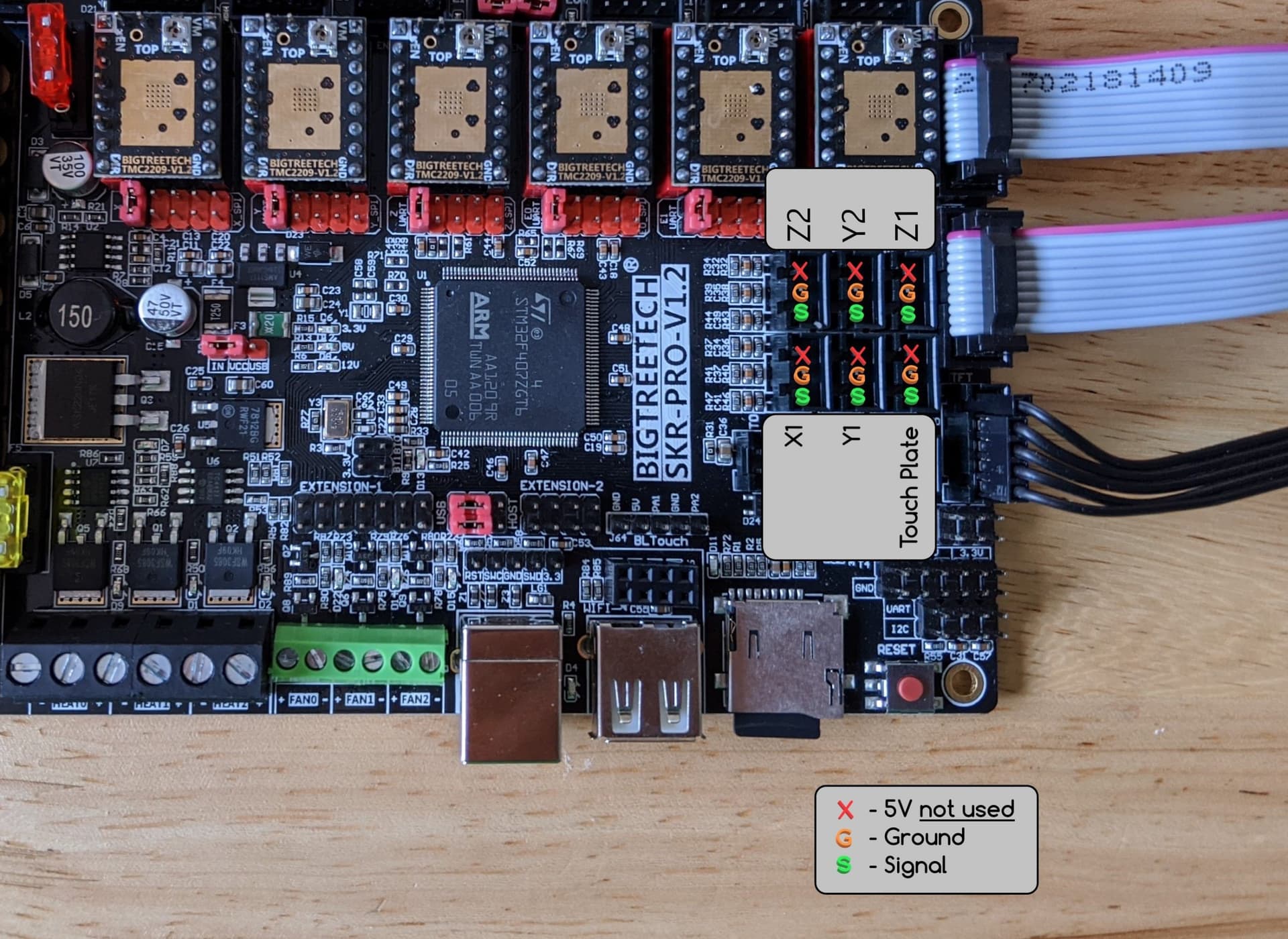
EDIT - Thanks to @SlowRider Matt for discovering this diagram on another thread. AND THEN I found it in the documents!!!
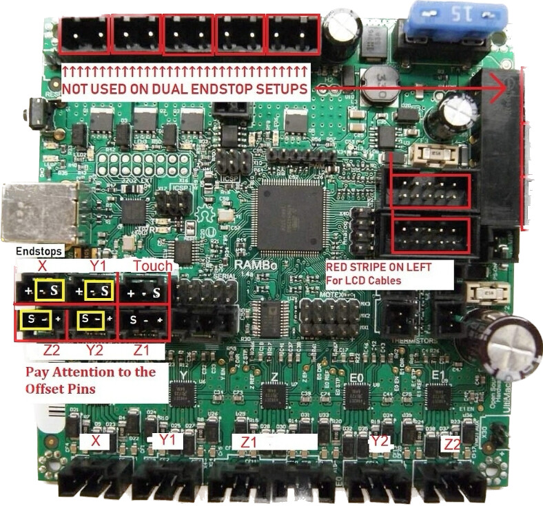
I’m pretty sure that the Y axis is self explanitory - Y1>Ymin and Y2>Y max so I have a third of it figured!
CORRECT
1) Since there is only one X stepper I presume it is X1>X min and X2>XMax can be ignored?
CORRECT
- I assume that both Z plugs are interchangeable - either can be plugged into either port?
CORRECT (both are Z1)
- The Z endstop is at Z Max, and presumably the touch plate goes into Z Min?
CORRECTION NEEDED Z1 and Z2 are interchangeable but Second Z endstop plugs into port labelled X Max
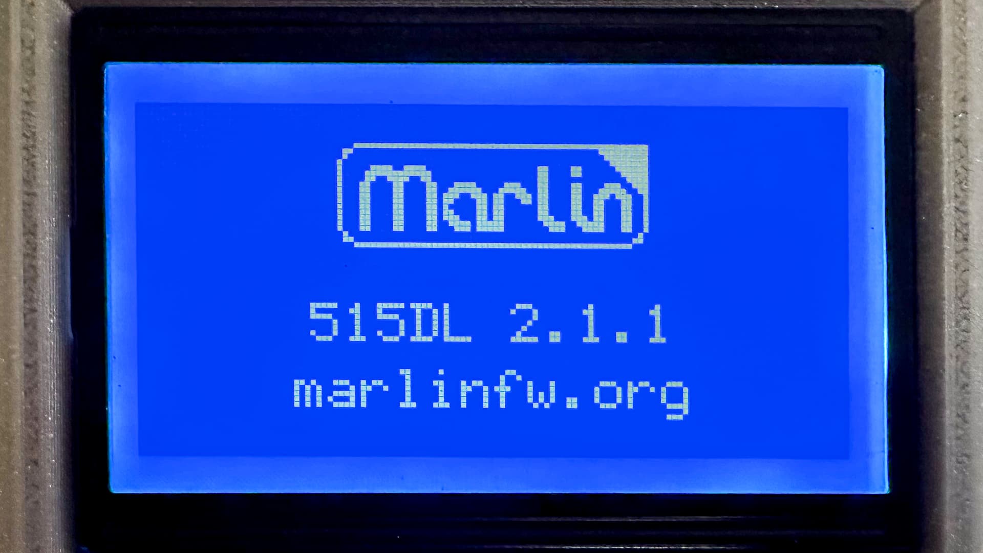
- I think I have to update the firmware (shudder) can I confirm please that the correct version is:
V1CNC_Rambo_DualLR-2.1.1
CORRECT? A HUGE shoutout and thank-you to everyone who has contributed to making flashing the board such a simple step-by-step operation. Everything from installing the Visual Code app to PlatformIO and the upload itself was so clearly explained that even this very nervous non-techhead had an almost great time doing it! Phew!
I thank you all for your help here, I’d love to end the day NOT on the waiting list for a new board!
I’m not going to be a ton of help here since I don’t run the same board as you. But I’m going to do some more digging to try and find the correct answers. I cant remember what board I ran on my old LR2 but I know it wasn’t an SKR so it could have been that one. Might be some info in my old thread for that machine.
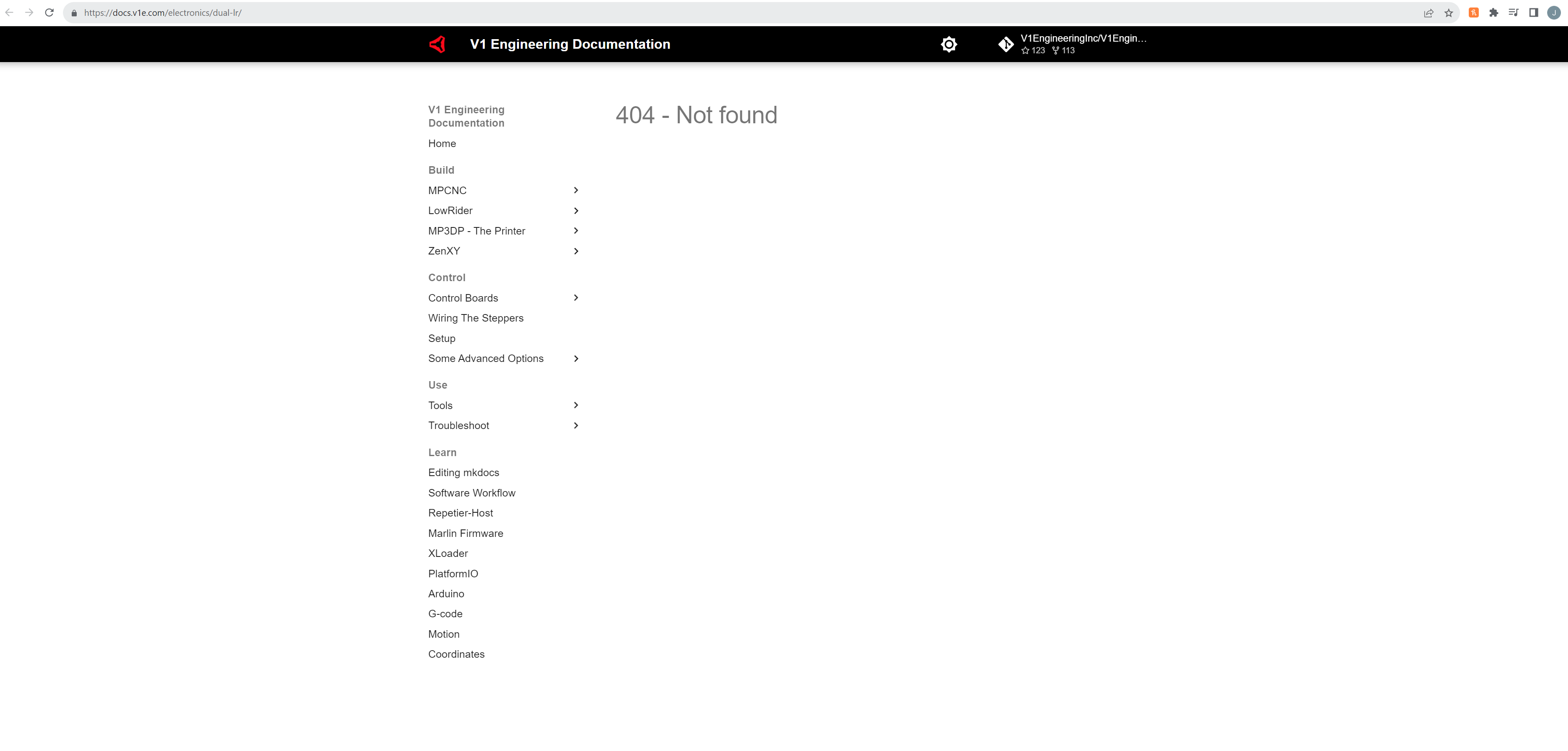
The docs only show wiring for the Primo…not the LR2/3 so this is going to be a tough one till someone smarter than me comes along
cant interchange them. Each endstop needs to be connected to the correct Z. Same with Y. If they are backwards the machine wont home. If you have them opposite then when the Z1 endstop triggers the Z2 motor will stop and Z1 will keep trying to go up and start skipping steps. Z2 motor will never get to the endstop. hopefully that sheds a little light on why it does matter.
Let me do some digging before I try to answer anymore. Will report back shortly…
1 Like
Well…this sucks…
I’m googling and all trying to find a wiring diagram for LR on the rambo but this is what I keep finding LOL.
This is the wiring diagram for the SKR.
I would think it would be the same but I’m just not sure so hopefully someone who knows more about your board will say for sure. Sorry I wasnt able to be more help but I know someone else will fix you right up.
Glad to see you making some progress! That sure is some beautiful work you are doing! Honestly seeing your work is giving me the drive to clean up some of mine! Thank you!!!
1 Like
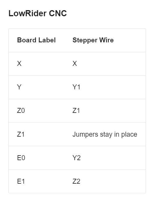
Here’s a screenshot I had on my phone. Don’t know if it’s helpful.
Edit: it’s from this thread: New Low Rider 3 Build Rambo 1.4 X2 trouble
3 Likes
That looks like the one @bitingmidge needs!
2 Likes
Well discovered Matt!
Thank you to you and to @Jonathjon for the speedy replies!
@SupraGuy I think this was your illustration? (from the linked thread) - can it go into the docs somewhere or is it already there?
I was pretty much correct with my deductions but there’s no way I could have guessed the X2 endstop! My hat is off to all those who have gone before and know about this stuff.
3 Likes
Phew! Now that I’m fairly sure I know what I’m doing with the wires, and the board is flashed correctly (I hope!) I feel like I do after a big day at the dentist… relieved and ready to get on with life!
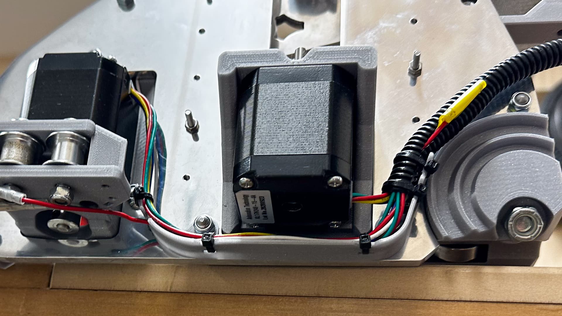
Here are some more pics of my “cable trays” and which are a better explanation of them that my response to @vicious1 Ryan above, including a photo of the stock setup. I would have twisted and bound the cable with loom tape in the end (so therefore this photo does not represent what might have been) but it does clarify the difference between the two.
Please note that when using the fenders/covers the clips do prevent use of the standard zip tie points, but it’s all a bit clearer without them mounted.
Also the 6mm plate does force the cables into mid air a bit - this tray is around 16mm wide, but for a thicker plate I’d tend to drop it to 10mm I think.
5 Likes