Formula 1 practice finishes at 11:00pm in Aus, and so did my print!
Once again the value in prototyping is clear:
The good:
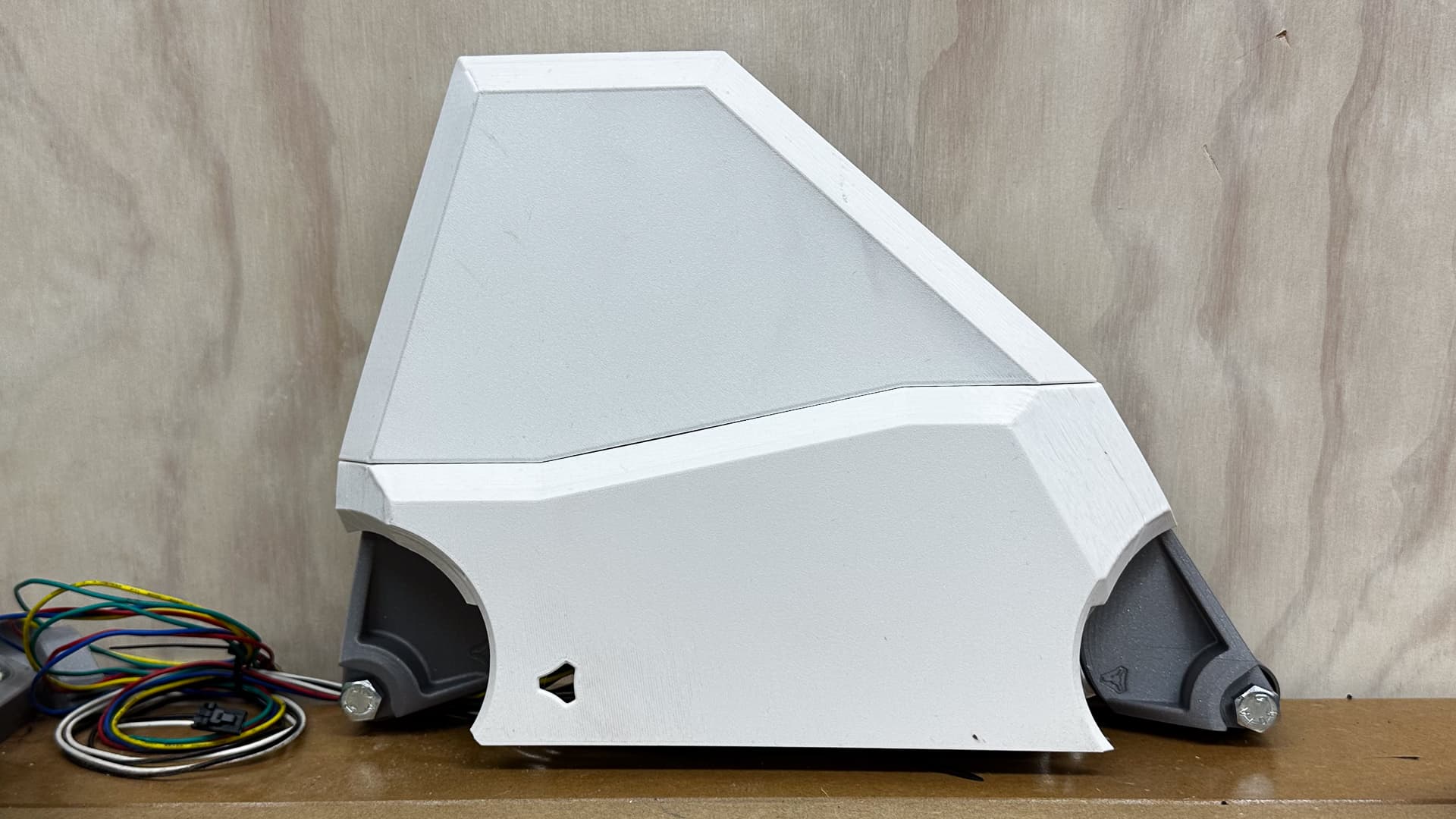
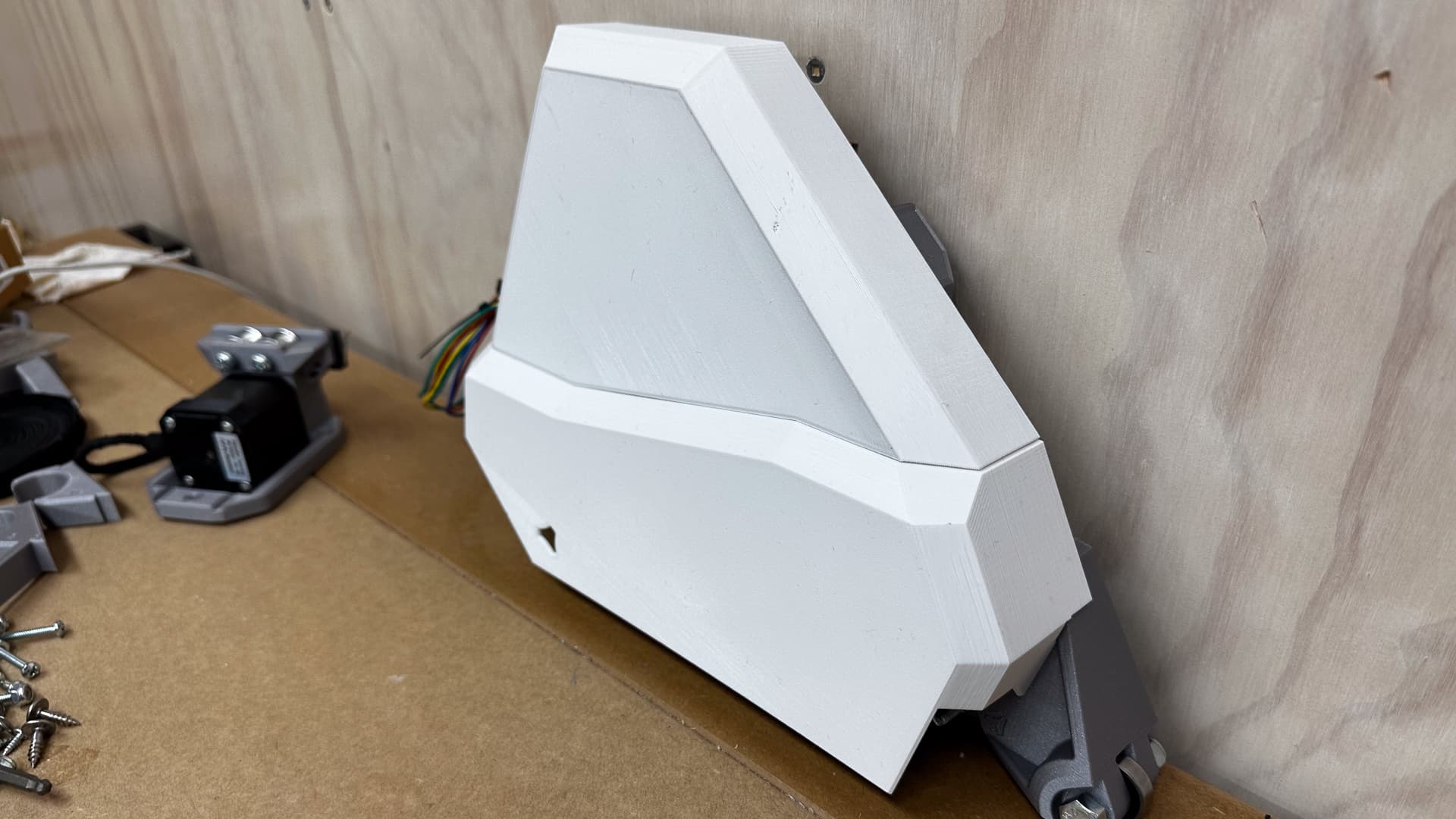
I think the overall proportions are pretty good, (except for the wheel arches - more on that later) - it looks fairly close to my concept sketch a hundred or so posts ago.
The fit is perfect, so no tweaking there.
It all feels solid and as though it was meant to be.
The bad:
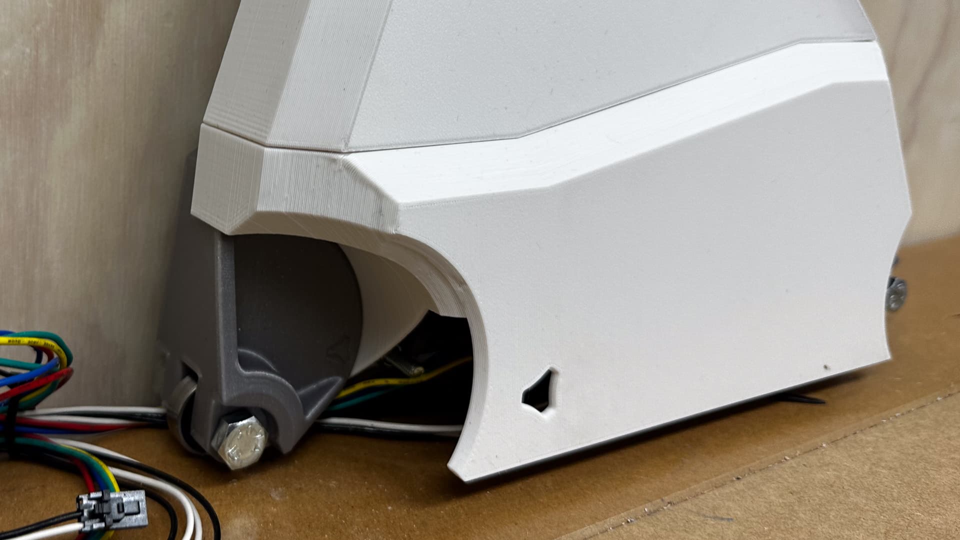
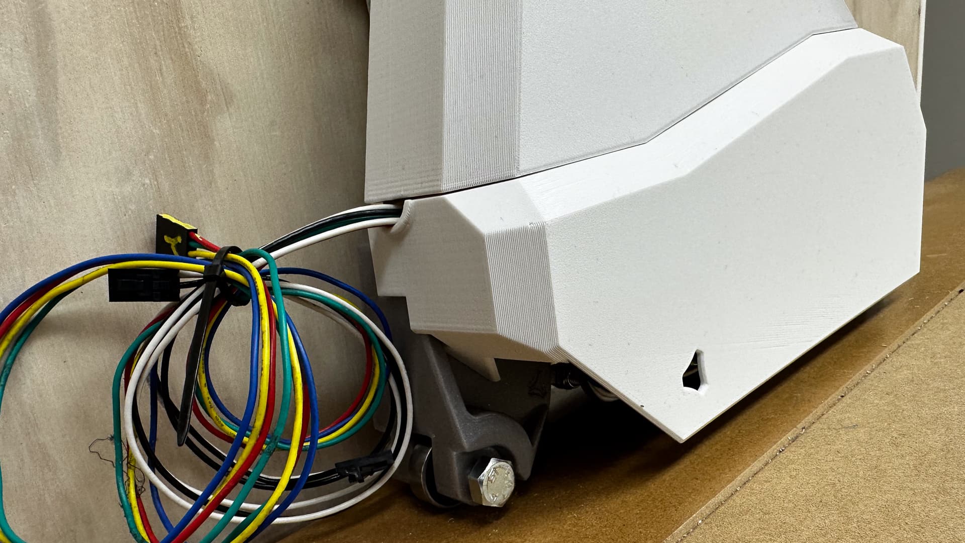
Those wheel arches! I tried to match the curves on the bearing brackets but by the time I added cutouts for the end stops and so on, it all became a bit of a dogs breakfast and a bit like an anteater with that skinny little snout hanging out. I am going to ditch them and make the end detail more angular which will make more sense when combined with the rectangular penetrations for the belt blocks.
I broke the lever on the end stop switch forcing it over what I thought was a bolt. Just as well I ordered a spare - I’m not sure if I can repair it but of course I’ll give it a go.
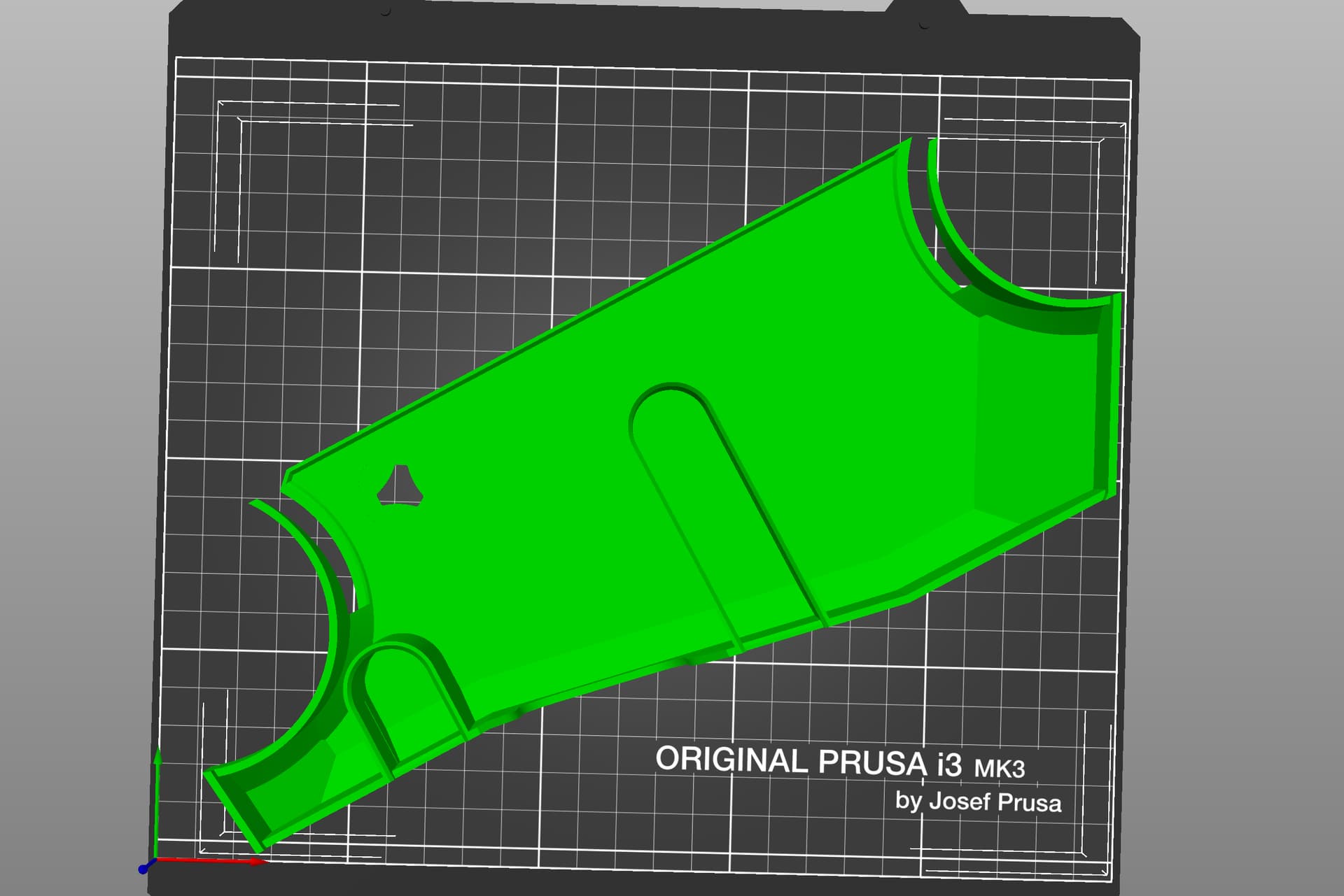
I also got the leading angle of the bottom bit slightly wrong so it’s considerably less than 45° at the moment and while it’ll look prettier printed in smaller layer lines - I’d rather fix it now. That gives me another tricky angle to resolve.
I don’t have too much room to manouvre to fit it on the build plate either!
As mentioned above the clips aren’t strong enough either, but at least with the base there is scope to add a couple of screws concealed from below if I can’t make it work.
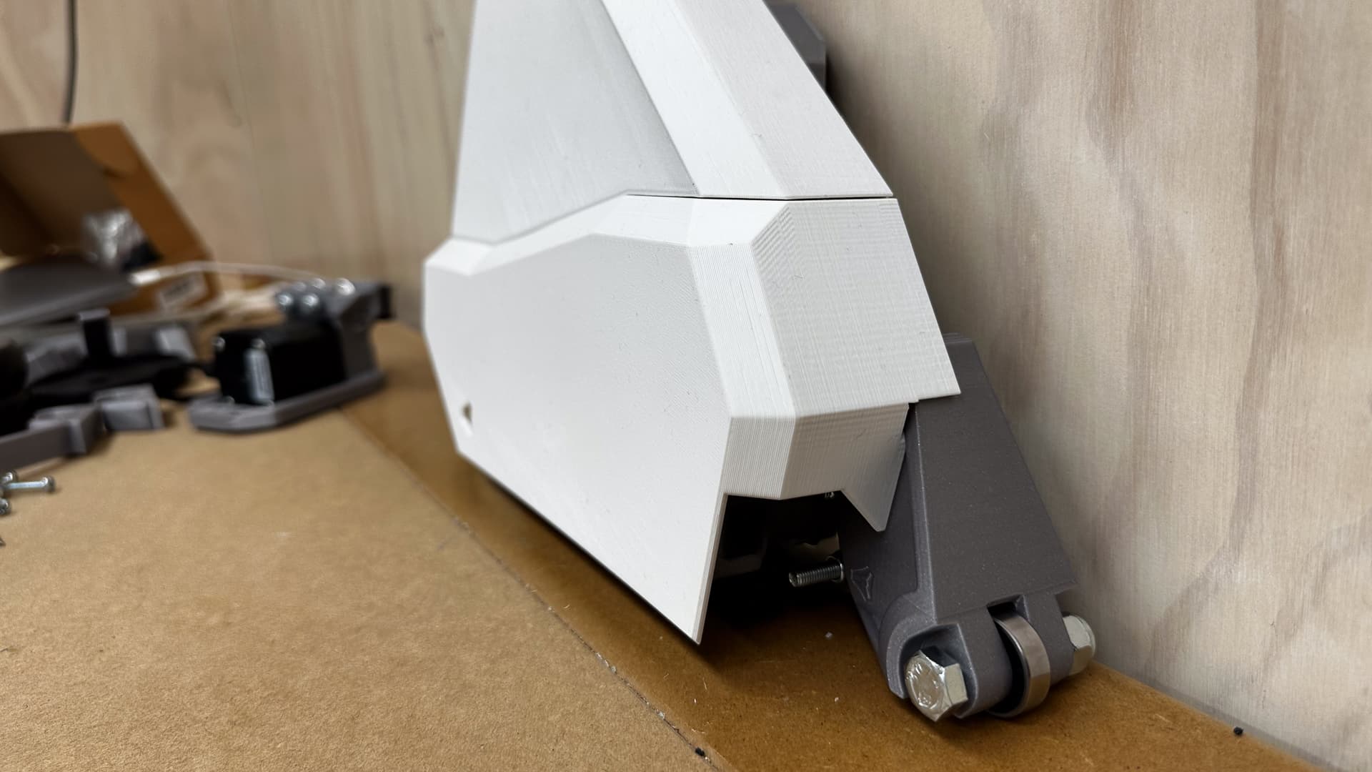
All in all it’s pretty pleasing, it’s a bit soon to say it’s done, but it’s really on its way.
Lol! Mine still has the 60mm skate wheels on it. I meant to switch to the 608 bearing, but havent actually done it, since getting my Z leveling sorted, but it would probably look better with the fender.
After more time than I care to think about tweaking the bottom fender, I think it’s heading in the right direction and we might even have a photo of the next one in an hour or two.
I printed a new set of clips in PETG with 2mm wall thickness and the difference is remarkable, but I have a feeling that in this situation they might just be too brittle, so I’ll try PLA tomorrow.
In the meantime, I know you are all too kind to make comment, but all my screws are exactly the wrong length, so they need to be trimmed.
As promised, when you want to cut screws neatly and to perfectly repeatable length this is how to do it. I will be chamfering the ends before I finish - will probably describe how later, but it’s just something with a hole in it that I can hold the screw while I spin it with the driver against a linisher.
Find a block of timber that is shorter than the drill bit that is close to exactly the size of the bolts you are going to cut, and drill through it. If your bolt is bigger than 1/4" or 6mm, cut a slot lengthwise as shown below, then cut another slot at EXACTLY the length you want to cut the bolt.
If you are cutting a larger bolt, mount the block in the vice as per yesterday’s post, and use the vice to clamp the bolt in place. For smaller bolts I prefer to run a clamp lengthways, to hold the bolt securely in place with the head pushed firmly against the end.
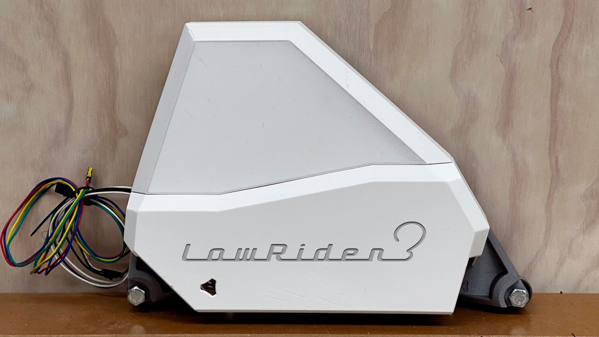
There are just a couple of tiny details to take care of, but this looks like a bought one, so I’ll start printing the pretty version tomorrow, and not a minute will go by of the eight hours for each half when I won’t wish I had a Mk4 or Bambu (just for two days mind - then I can go back to being very content).
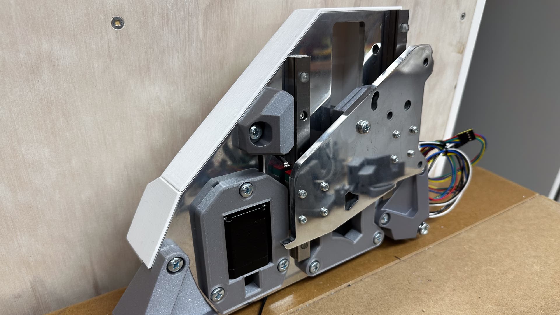
I am really happy with this - the proportions eventually sorted themselves out (with another four hours or so of prodding admittedly). It looks a little overbalanced at the moment with the bearing way out to one side, but I am pretty sure that once the belt is in place it will be fine. (Tonight might be a good time to check that the belt actually clears everything!)
I am still a little unsure about the catch - it’s all a lovely firm fit and I’m inclined to go with it as is - it’s easy enough to conceal a screw underneath if it vibrates loose, but I think that’s unlikely.
This one is something that could be done as an embedded design of of the 3D print of the part (sunk in letters, using standard bridging feature of the slicer):
I think the idea is to mimic the car badges, some chrome lettering sticked on top of the fender
But yeah this could easily be included in the print (either embossed or raised)
Definitely that’s the ideal. Just was thinking about two aspects: repeatability for the average person who does not want to get into metal plating, etc, and a placement guide for those who do.
Will share the files of course (once it’s shareable) and I’ve actually assembled it
I think I have set it up to make it reasonably easy to change the thickness of the plate, but need to go back and make all the offsets are variables so that I’m not chasing my tail.
If anyone’s desperate to road test, just let me know.
My original idea with the badge was to imprint it as you have shown ( a little smaller and in line with the cutout emblem), but printing recessed lettering on the build plate like that can give very mixed (sometimes awful) results over a wide range of settings.
No need to chrome the badges though - I just use half a dozen coats of spray gloss acrylic.