Sorry Jeff, probably not using the right words…to put it straight at least for me :rofl
ESTL is one of the software programs that generates the necessary G-code, then that G-code can be saved into an SD card to run it on the SKR, CNC moves in my case are controlled from the TFT attached to my SKR board.
Repetier Host can do the same but from a computer connected to the SKR in case there’s no TFT to control the CNC moves.
Am I right? Did you understand my very poor writing ?..I’m not English native as I’m sure you already know, so it’s a bit difficult to try and put my thoughts down in words and specially when these words need to be very technical…sorry for that and thanks for your understanding Jeff, you’re being very very helpful.
It must be frustrating to try to have detailed technical talks in a language that isn’t your first. I can’t do it, so I am empathetic.
Repetier host is what I call a “gcode sender”. So is the TFT. They serve the same purpose. They have enough control to set up the machine (jog here, set zero there, etc.) and then they just play the gcode file, one line at a time.
Estlcam does do the “CAM” step, which is taking your design and creating a list of gcode commands to execute. It stores those in a gcode file. Estlcam also has gcode sender capabilities in it, but it isn’t compatible with most of our controllers. It won’t work with the SKR. So instead, we save the gcode out of Estlcam, and we put it on the TFT SD, or we load the file in repetier host and hit “print”.
That is the long way to say, I think you are right.
Perfectly put together…I could not have said it better Language is not really a problem, is the lack of knowledge of technical language…I lack it too even in my own language, I supose I’m more of an end-user than a developer…but it’s nice to learn new concepts, words, etc… To me this is a fascinating world…complex but opens a new dimension on projects and things…
I’m a bit stuck on the build, redesigning a few other people improved pieces for the tensioners to adapt them to the hardware I have at home…M6 threads and bolts…etc…Need to sort the most important one which is the X tensioner, don’t fancy the ties, tried other builder piece but not too happy with it, so I have my brain going round and round to find the right and definite design.
In any case I’ll finish it today to have it doing the Crown Test or I’ll die trying it !!!
Thanks to @basgoossen for sharing his endstops…also I’ve redone the Y-retainers to fit M6 standard Hex full threaded bolts…so if anybody needs to use them, let me know…once tested I’ll upload them to thingiverse.
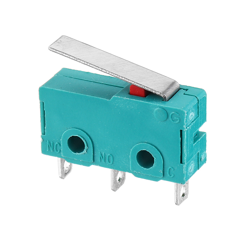
I’m soldering the wiring for the limit switches and need some advice, as per guide should be done on NC position, is that wiring both end connectors in my picture ?
The picture is too fuzzy for me to see, but you should find “NC” normally closed, “NO” for normally open, and “C” for common. I don’t know if there is a standard arrangement so you must read the letters or use a multimeter to find out which is which.
Jamie probably my fault, it’s not ON but NO, NO and C, I had to take a magnifier as I couldn’t see it myself…so I guess for NC I should solder each end ??? Pins to solder would be NO and C…I haven’t got a clue on hiw to use a multimeter
It should look like this with one “NC” and one “NO” and one “C”. I didn’t have one handy to take my own picture but after looking at a bunch of pictures online it appears that normally closed (NC) is always opposite the “C” position and normally open (NO) is the middle connection.
So yes you would solder the two outside ones and leave the middle tab unconnected. This is for normally closed configuration.
The lettering is so small that it could perfectly be NC NO and C…and me being a complete novice on the electronics scene does not help at all. Thanks for your help and time.
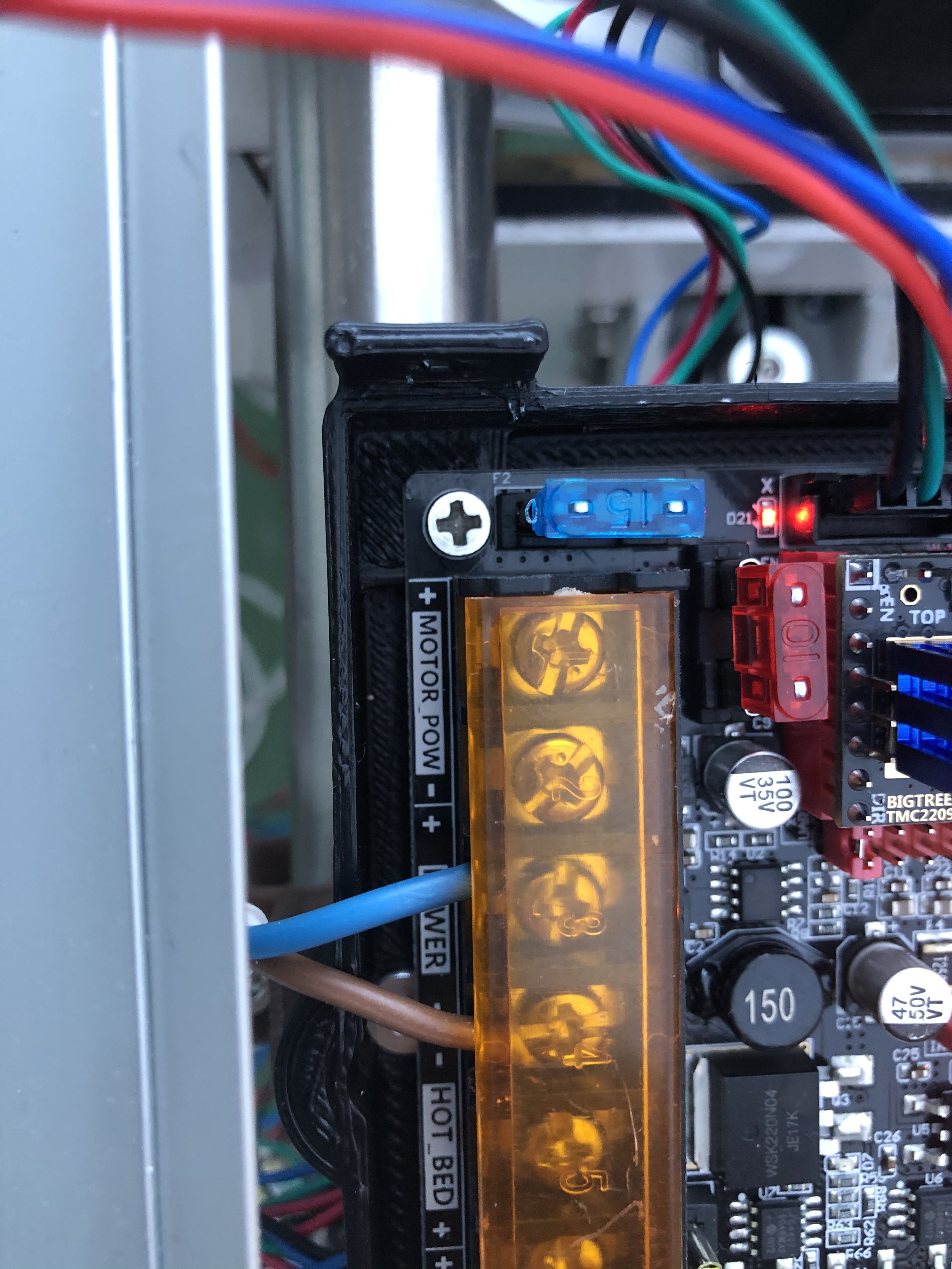
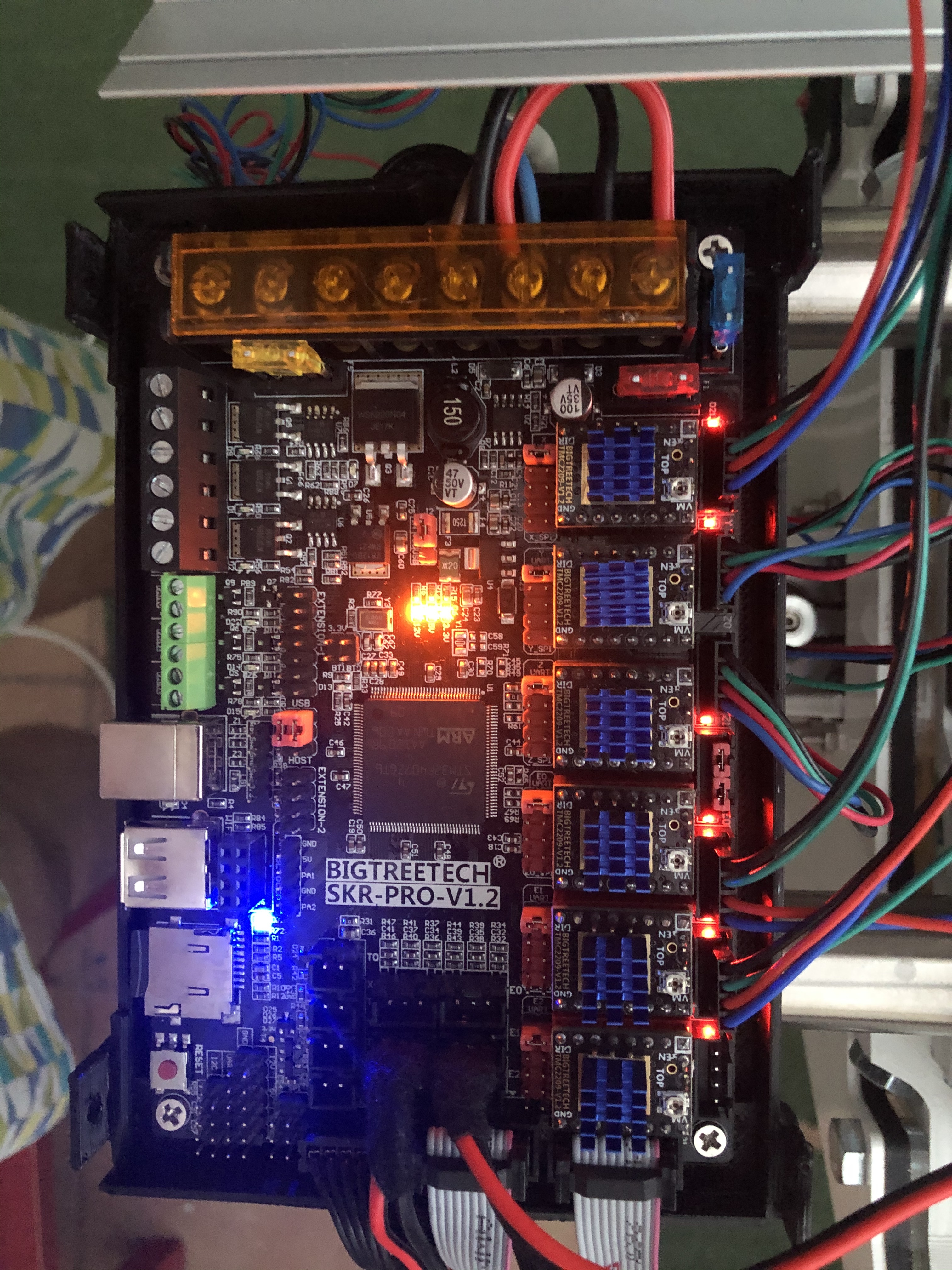
Yes. The way you have it wired with motor power in the second pic is right. You need to have the baud rate set to 250k. I see you’re using espanol, did you compile that firmware yourself? The one in V1’s github is needed to work with this firmware.
Hi @jeffeb3 , I didn’t compile anything I haven’t changed the language actually…it’s in English and some bits in spanish, haven’t got a clue on how to do it …I flashed it with the firmware.bin you told me to…but touch screen won’t let me move any axis manually, only when I get into Marlin mode…with the knob I can move axis around…I’m sure I’ve got something wrong as I can’t get the Y axis to touch the endstops…and on the main screen as you turn the board on it shows axis X and Y 0? and Z=200…I need to understand which way they should move as I tried to print the crown and started going the wrong way…so stopped it and thought I’d better ask the experts…
So I understand I must change the connectors backwards…btw do you know why is it not going to the end of the table and touching the endstop switches?
Could it be something to do with the firmware not being properly flashed on the SKR board?
I tried do the crown but went off the wrong direction…I have the gcode to start on the left side of the table and then move to the crown which is set at the right of the start point…but instead it went to the left…not too sure if I have the right settings on the board and I don’t know how to check it.
Thanks,
Here’s my Gcode if it helps…
;Project 0102
;Created by Estlcam version 11 build 11,231
;Machining time about 00:02:10 hours
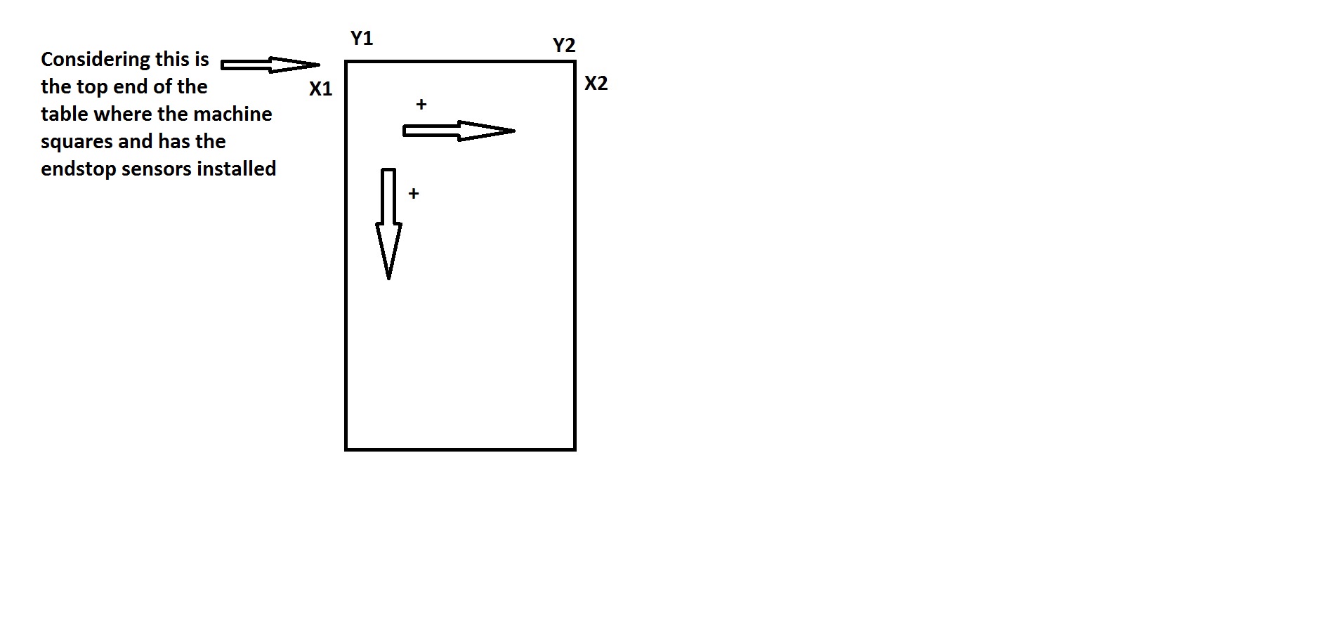
I was just going by your diagram of the directions and assuming the position of the viewer as facing the bottom edge, if you jog the machine is that accurate? For me, facing the machine from the rightmost long end with the electronics to my left, I jog x in the positive direction and it goes right, jog positive in the y direction and it goes away from me. It seems to match up with what I do in CAD, and I don’t get mirroring, so I assume it’s correct enough. (reversing x and y is an option too, I did that for a while)
If you are homing you are using the min end stops, the max end stops cut the power when hit. At least for me. I don’t use them myself on my low rider as knowing where the corner of the work piece is more meaningful.
To check it just jog the machine using your gcode sender software, or if you have an lcd with a file on an sdcard, go to motion, y axis for example, pick 10 mm and turn the knob or use the touch screen, whatever you have set up. I didn’t read the whole thread, just saw the diagram and it seemed different to me.
You are going a bit faster than me on Z, if it works for you, great, but I stick below 300, it screams less.
My files have this at the beginning:
G90
G92 X0 Y0 Z0 ; the tip of your bit is 0, 0, 0
G21 ; numbers that follow are in mm, G20 if inches
You can set that up is estlcam.
You are starting at the bottom left on my machine, I’ll skip the rest, it’s all within the 100mm first square for the first few etching sections and at the end.
You need to flash the tft too. There are files to put on an sd card and put into the tft and reset it. It will tell you it is updating and then reboot and you can remove the sd card.
Before trying your own gcode, make some movements on your own and make sure positive X goes right, positive Y goes away and positive Z goes up. Then male sure a 10mm movement in each direction is actually 10mm.
Then, use the gcode test crown. That will check out the machine oretty much completely. After that, post a pic of the crown here and try to follow the estlcam basics and make your own.
 Language is not really a problem, is the lack of knowledge of technical language…I lack it too even in my own language, I supose I’m more of an end-user than a developer…but it’s nice to learn new concepts, words, etc… To me this is a fascinating world…complex but opens a new dimension on projects and things…


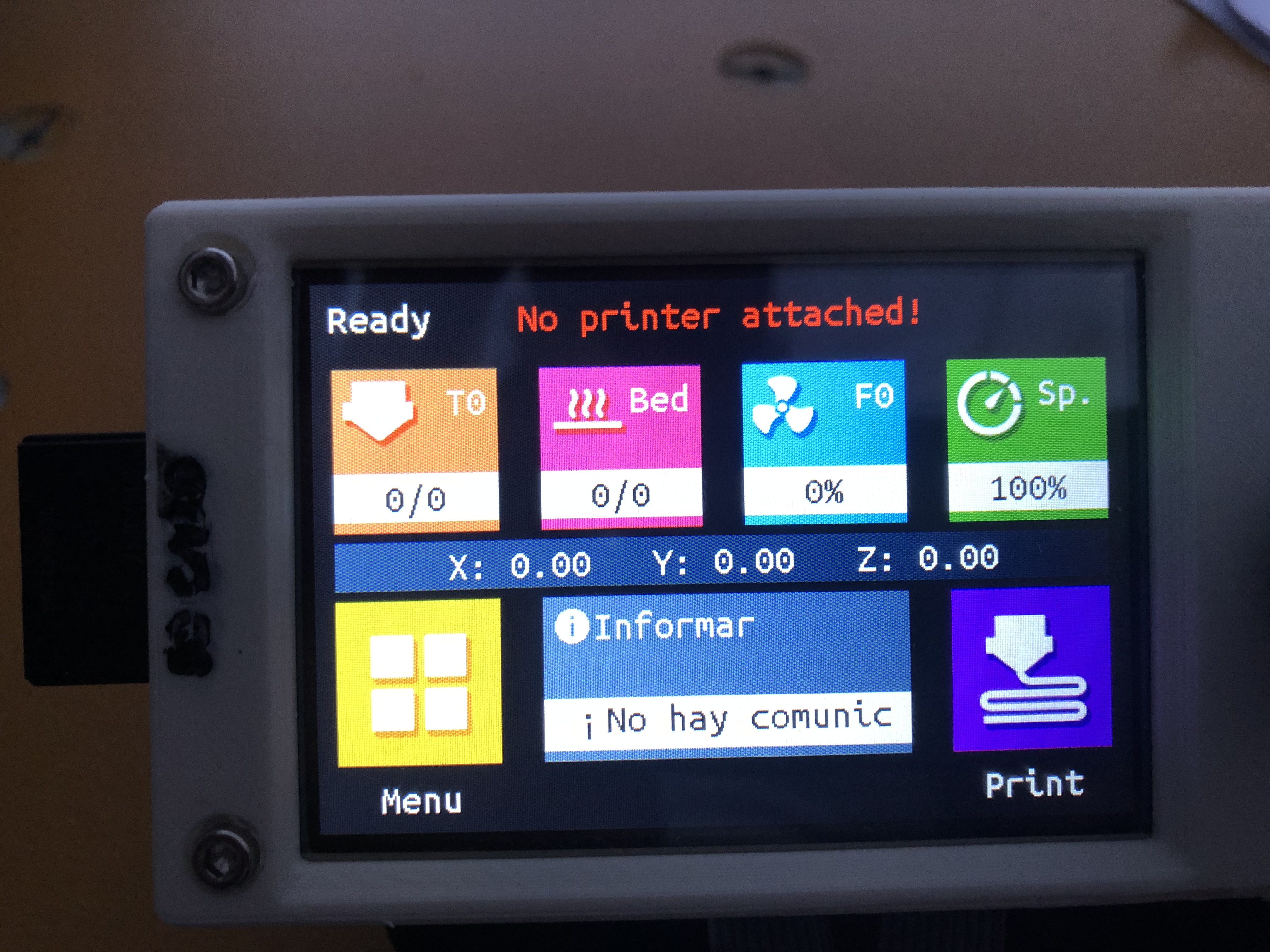

 …I flashed it with the firmware.bin you told me to…but touch screen won’t let me move any axis manually, only when I get into Marlin mode…with the knob I can move axis around…I’m sure I’ve got something wrong as I can’t get the Y axis to touch the endstops…and on the main screen as you turn the board on it shows axis X and Y 0? and Z=200…I need to understand which way they should move as I tried to print the crown and started going the wrong way…so stopped it and thought I’d better ask the experts…