I’ve built the lowrider v4 and completed a few basic projects on it. As I learn (and make mistakes), I occasionally have missed steps when I my passes are too aggresive. These missed steps ruin the workpiece when the CNC loses position and continues trying to cut in the wrong position.
Has anyone tried using the stallguard feature associated with the Jackpot drivers as a sensor to detect missed steps? My thought is to write a macro that’s triggered when the stallguard hits a threshold that suggests the machine is facing more resistance than it can handle. The macro would then lift the gantry off the workpiece and throw an alarm.
This wouldn’t correct the position of the machine after a missed step, but it could prevent the machine from carving a chunk out of a workpiece when I’ve set my feeds and speeds incorrectly.
Any thoughts on whether this would work or better ways to detect and respond to missed steps?
The stallguard has been talked about a few times around here. I am not the best to explain it but I will try
The load varies so much on the motors going through a cut that it makes it extremely hard to tune. Also I am not sure that we can even use that feature in fluidnc, but I could be wrong.
Yes, I’ve done this. In my experience, it works in theory but not in practice. The issue is the value is speed, material, and depth dependent. So, you can get it to work, but not reliably.
The best takeaway here is if you skipped steps your CAM is drastically wrong. Stall guard might help a little but test cuts and more correct CAM are a better option here.
I just did tests at 10lbs force and there is zero missed steps at the lower holding torque. If you are exceeding 10lbs on a cut, you need to cut your material removal rate by about half, or make sure you are using the right end mill.
Thanks Ryan, I’m getting good success at 850mm/min and 1.5mm depth on a 1/8” upcut.
My thought is on implementing this to mitigate mistakes in my CAM programming. I know I will continue to forget to set the depth of pass on one of my parts or tool changes in fusion. I’ve had a couple times where a piece is running well for a couple hours, and then transitions to the next section of code where I forgot a setting and I end up with a black scorch across the piece before I can stop the machine and router.
I’m an electrical engineering student and I’m looking for final projects this term that can improve my CNC. Adding some level of error/fault feedback seems like a good place to explore.
Do you think it has potential to work in extreme cases - throwing a fault at very high levels of resistance? Are you willing to pass along the code you used to implement the test?
In what material? In anything other than metal that is very very slow so I would assume a bad endmill or maybe your spindle is running backwards. We need more details, on your build, steppers endmill, router, material.
That is just it. In anything other than metal 2mm/s-50mm/s should work 1mm doc to 12mm doc should work. If you skipped steps something is drastically wrong. The machine is already built with a huge range of acceptable so when I hear skipped steps I know something else is wrong.
If you wanted to see that I would suggest trying to add some load cells to watch real time load on the XY axis, that will tell you way more than adding power and not knowing it. Plus I would love to see this!
If you really want to go this route, you need encoders on the motor and closed loop control.
That’s already available in the FluidNC ecosystem if you use a board like a Doberman and external closed loop stepper drivers.
Note- this won’t “Fix” bad CAM, so your lesson to learn is exactly what was shared above- understand your machine and material, and stay within the capabiliteis therein.
Still a work in progress, but we have hit the deadline on the classwork part of this.
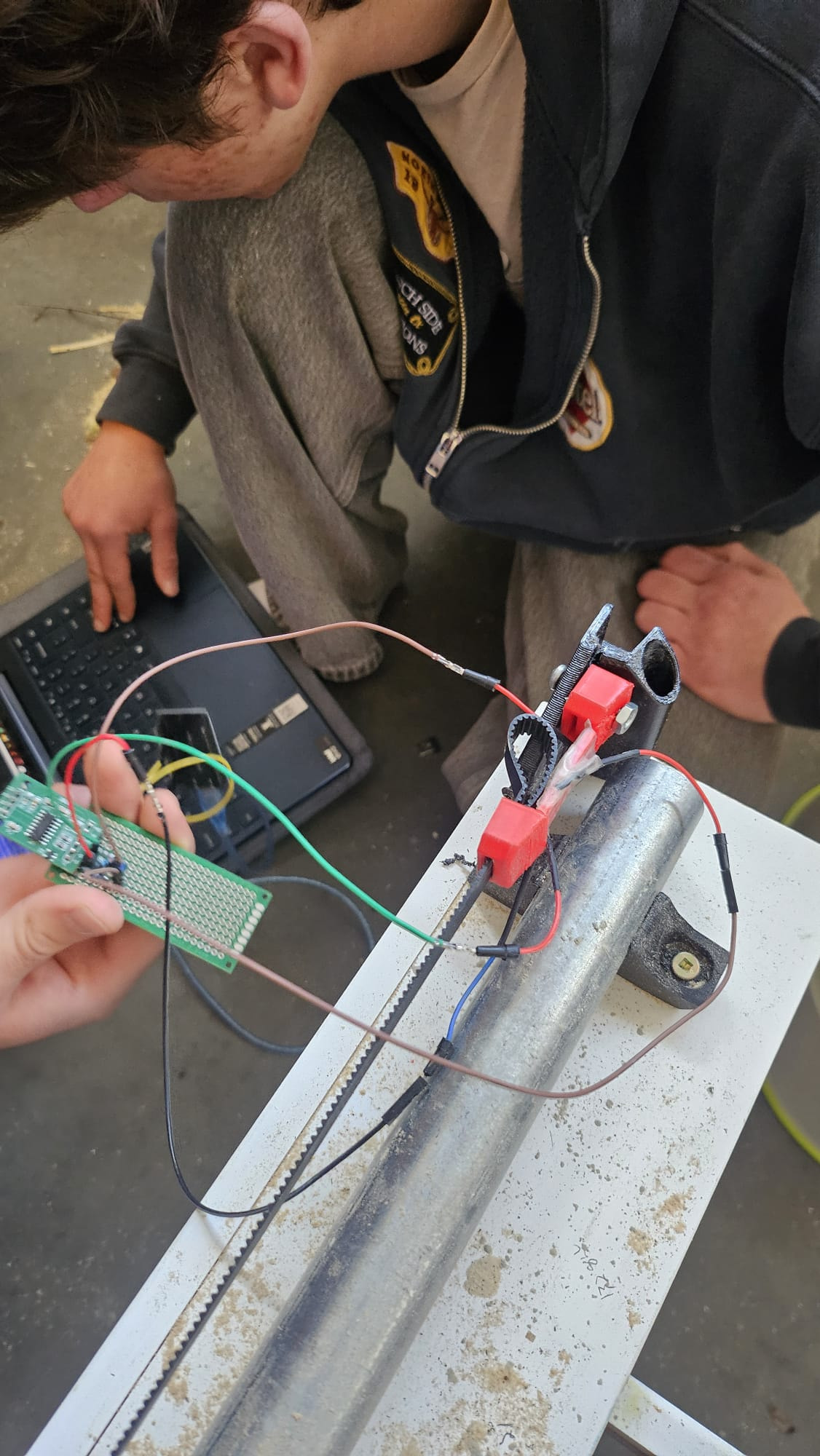
We implemented a very basic load cell. We modified the belt nuts to include a straight segment where we could mount the strain gauges. The gauges register the strain of each axis.
The next steps are to move the load cells from the negative end of the axis to the positive end to get out of the way of the homing cycle. We then need to calibrate the load cells with a known load so we can see real rather than relative force values.
The load cell shows a clear peak and sudden drop when the stepper skipped steps.
Error avoidance:
When the force gets close to the maximum our machine can handle, the arduino running the load cells throws a signal to the Jackpot controller’s limit switch pin. The system aborts the program and throws an error letting us reset the machine.
The next step is to configure the machine to adjust speed based on the force rather than simply abort the program. This will reduce the learning curve on running the CNC and let us really push the limits of machining speed without worrying about scrapped work pieces.
That’s a cool idea using the belt directly as the strain material. What are the key advantages you see to doing it that way? Are there any downsides you can think of like a lack of linearity? Would there be any advantage to designing a more conventional/COTS load cell into the belt anchor?
Being able to measure actual belt tension during assembly would be a potentially useful feature to have, currently that’s a part of the assembly process that I suspect has very wide error bars on it, machine-to-machine.
Some form of real-time cutting force feedback would be an awesome feature to have, I measured spindle power a while back thinking that’d be a fun thing to have available as realtime or logged feedback, potentially providing a good method for determining tool wear or helping to debug setup issues.
Seems like a really promising idea. It’s similar to the accelerometer approach used for 3D printers but in a method that’s much more appropriate for a lower speed/higher force scenario like a CNC router.